© 2017, IRJET | Impact Factor value: 6.171 | ISO 9001:2008 Certified Journal | Page 1656
OPTIMIZE CONTROLLING OF ACTIVE FILTERS CONTROLLED BY PI
CONTROLLER
Md. Tanwirul Hasan
1, Ashutosh Gupta
21,2 Electrical and Electronics, Engineering, IASSCOM, Bhopal
---***---Abstract : Due to increasing non-linear loads various undesirable effects and power quality problems induced. The use of power converters, electronic equipments and other non-linear loads are rapidly increasing in industry and also by consumers, draw non-linear currents from the AC mains as compare to traditional loads such as motors and resistive heating elements. This leads to the distortion of power system voltage and other problems. This paper presents an auto tuned active power filter for harmonic minimization and reactive power compensation of non-linear load under fast load variation condition. Improving dynamic behavior of shunt active power filter is used to tune PI controller coefficients and make it robust under random load variation.
Key words: Active filter, PI controller.
1.1 Introduction
Active power filters are more and more capturing the interest of researchers and industries owing to the decreasing quality of power supplied by the electrical distribution companies and the difficulties in fulfilling the constraints imposed by national and international standards only by using traditional compensating strategies.
The use of active systems for compensating harmonic distortion and reactive power in the supply electrical networks, both at user level or at a higher voltage level, is now more often preferred to the classical passive compensating methods. In fact active filters do not present all the typical drawbacks of passive systems such as the detuning of single tuned filters due to changes of system operative conditions and surrounding environment or the generation of resonance at particular frequencies, between the network and filter reactance, that amplifies unwanted harmonics.
In a modern electrical distribution system, there has been a sudden increase of nonlinear loads, such as power supplies, rectifier equipment, domestic appliances, adjustable speed drives (ASD), etc. As the number of these loads increased, harmonics currents generated by these loads may become very significant. These harmonics can lead to a variety of different power system problems including the distorted voltage waveforms, equipment overheating, malfunction in system protection, excessive neutral currents, light flicker, inaccurate power flow metering, etc.
To reduce harmonic distortion and power factor improvement, capacitors are employed as passive filters. But they have the drawback of bulky size, component aging, resonance and fixed compensation performance. These provide either over-or under-compensation of harmonics, whenever a load change occurs [4]. In over-order to overcome these problems, active power filters (APFs) have been developed. The voltage-source-inverter (VSI)-based shunt active power filter has been used in recent years and recognized as a viable solution [5].
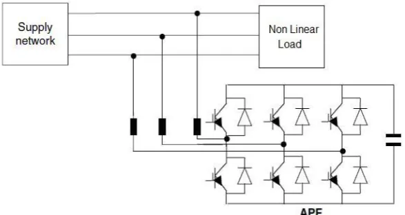
Active filters, besides, permit the control and the compensation of distorted line currents adapting themselves to the load changes and to changing in working frequency. The most effective and the most diffuse structure in active filtering systems is certainly the shunt one composed by an inverter fed by a capacitor and a passive filter used to inject the compensating currents in the grid (Fig. 1). The aim of this kind of active filters is to generate a current waveform that is equal, but with opposite phase, to the harmonic content of the load current and to inject it in the a.c. supply system. In this way the a.c. mains will approximately deliver only the fundamental current component also with the possibility of a compensation of the find a mental reactive power.
© 2017, IRJET | Impact Factor value: 6.171 | ISO 9001:2008 Certified Journal | Page 1657 Recently has generated a great deal of interest in various applications and has been introduced in the power electronics field [8]-[10]. The advantages of over the conventional PI controller are that they do not need an accurate mathematical model; they can work with imprecise inputs, can handle nonlinearity, and may be more robust than the conventional PI controller. Use of for minimization of harmonics and improvement of power quality is not a new issue rather various authors have introduced some innovative methodologies using these tools [11].
The most important observation from the work reported by various researchers for power quality improvement is the design of active power filter under ‘fixed load’ conditions or for loads with slow and small variation [12].
2. ABOUT THE ACTIVE POWER FILTER
When linear loads are connected to the supply the waveforms are linear. Whereas nonlinear loads are connected harmonic appears on electric voltage or current. The harmonics are integer multiples of system frequency. This leads to various power quality problems like heating of the devices, mis– triggering of the drives, pulsating output in the motors, etc., A harmonic filter are used to eliminate the harmonics. There are three basic types of harmonics filters given below.
Passive power filters
Active power filters
2.1 Passive power filters (PPF)
PPF is a type of filter, which consists of only passive components. It consists of linear elements like resistors, capacitors and inductors. They are also called as LC filters, which produce series resonance or parallel resonance that forms a major drawback of this type of filter. Another drawback of PPF is the cost which increases as the voltage rating of the inductor and capacitor increases.
2.2 Active power filter
APF is a type of filter that uses either current or voltage source as its major component. They compensate voltage or current harmonics by injecting the negative of the harmonic signal measured injected signals fed are of same magnitude but in phase opposition with the measured harmonic signals. Of these two voltage source based APF is more advantages.
[image:2.595.149.443.528.684.2]It is controlled to draw/supply a compensated current from/to the utility, such that it eliminates reactive and harmonic currents of the non-linear load. Thus, the resulting total current drawn from the ac mains is sinusoidal. Ideally, the APF needs to generate just enough reactive and harmonic current to compensate the non-linear loads in the line [12].
Fig. 1: Active power filter connected with transmission line
3. 1 Proposed PI control scheme
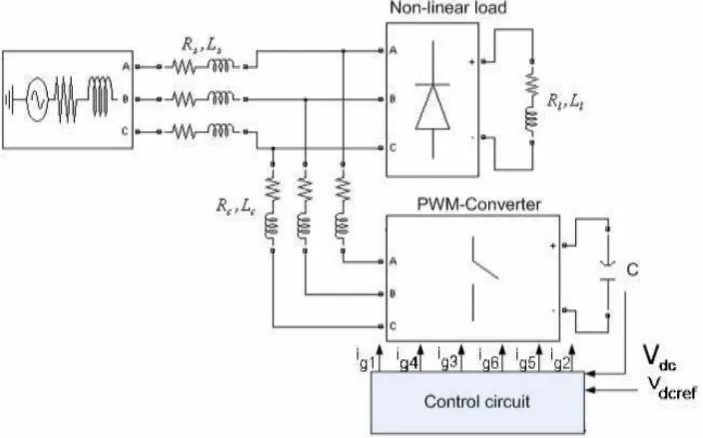
© 2017, IRJET | Impact Factor value: 6.171 | ISO 9001:2008 Certified Journal | Page 1658 sensed and compared with the reference value (Vdcref ). The Input of PI controller is the value of Error, e = Vdcref − Vdc , and its output, after a limit, is considered as the magnitude of peak reference current max I . The switching signal for the PWM converter are obtained from comparing the actual source currents ( isa , isb ,isc ) with the reference current templates ( Isa Isb Isc ) in a hysteresis current controller. The output pulses are applied to the switching devices of the PWM converter [14].
Fig. 2. Active filter controlling system.
Since coefficients of PI controller, K p and Ki , are fixed in this model, the performance of active power filter under random load variation conditions is not as well as ‘fixed load’ condition. To overcome this problem and make a robust controller is designed to tune K p and Ki on the base of load current value.
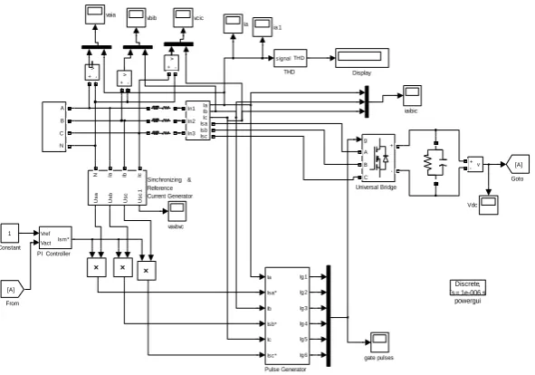
[image:3.595.135.453.509.675.2]3. Simulink model of Active power filter using PI controller.
Fig. 3 shows the block diagram of PI controller used for the controlling of active power filter.
Source PWM
Control Load
Current Controller
PI / Fuzzy Controller
+
-Vdc
Vref
Fig. 3 Block Diagram of PI controlled improved power quality converter
© 2017, IRJET | Impact Factor value: 6.171 | ISO 9001:2008 Certified Journal | Page 1659 Fig. 5. Simulated power circuit without controlled improved power quality converter
vcic vbib vavbvc vaia powergui Discrete, Ts = 1e-006 s. iaibic ia 1 ia gate pulses v + -v + -v + -v + -Vdc Universal Bridge g A B C + -THD signal THD A B C N Ia Ib Ic In1 In2 In3 Isa Isb Isc
Sinchronizing & Reference Current Generator
Usa Usb Usc Usc
1
N Ia Ib Ic
Pulse Generator Ia Isa* Ib Isb* Ic Isc* Ig1 Ig2 Ig3 Ig4 Ig5 Ig6 PI Controller
Vref Vact Ism* Goto [A] From [A] Display Constant 1 vcic vbib vavbvc vaia powergui Discrete, Ts = 1e-006 s. iaibic ia 1 ia gate pulses v + -v + -v + -v + -Vdc Universal Bridge g A B C + -THD signal THD A B C N Ia Ib Ic In1 In2 In3 Isa Isb Isc
Sinchronizing & Reference Current Generator U sa U sb U sc Usc 1
N Ia Ib Ic
Pulse Generator Ia Isa* Ib Isb* Ic Isc* Ig 1 Ig 2 Ig 3 Ig 4 Ig 5 Ig 6
PI Controller
Vref VactIsm* Goto [A] From [A] Display Constant 1 6. Conclusion
[image:4.595.152.448.386.593.2]Based on the simulation results, it can be concluded that PWM rectifier perform satisfactory for the compensation of line current. After compensation, line current become sinusoidal, balanced and in phase with the respective source voltage and reduces the THD of the source current below 5% limit. It is clear from simulation result that the transient performance of
Fig. 6. Simulated power circuit for PI controlled improved power quality converter
5. Simulation Results
© 2017, IRJET | Impact Factor value: 6.171 | ISO 9001:2008 Certified Journal | Page 1660 the source current and DC side capacitor voltage is better for the PI controller in term of the setting time and % rise/fall in DC link voltage. The steady state performance of the is comparable with that of PI controller.
References
[1] Akagi H., “New Trends in Active Filters”, 1995, EPE,17- 25.
[2] B. S., Malesani L., Mattavelli P., 1998, IEEE Trans. on Ind. Electron., Vol. 45,722-729.
[3] W. M. Grady, M. J. Samotyj, and A. H. Noyola, “Survey of active power line conditioning methodologies,” IEEE Trans. Power Del., vol. 5,no. 3, pp. 1536-1542, Jul. 1990.
[5] B. Singh, A. Chandra, and K. Al-Haddad, “Computer-aided modeling and simulation of active power filters,” Elect. Mach. Power Syst., vol. 27, pp. 1227-1241, 1999.
[6] K. Chatterjee, B. G. Fernandes, and G. K. dubey, “An instantaneous reactive volt-ampere compensator and harmonic suppressor system,” IEEETrans. Power Electron. vol. 14, no. 2,pp. 381-392, Mar. 1999.
[7] S. Jain, P. Agarwal, and H. O. Gupta, “Design simulation and experimental investigations on a shunt active power filter for harmonics and reactive power compensation,” Elect. Power Compon. Syst., vol.32, no. 7, pp. 671-692, Jul. 2003.
[8] B. K. Bose, Expert Systems, Fuzzy Logic and Neural Network Application in Power Electronics and Motion Control. Piscataway, NJ: IEEE Press, 1999.
[9] V. S. C. Raviraj and P. C. Sen, “Comparative study of proportional integral, sliding mode, and fuzzy logic controllers for power converters,”IEEE Trans. Ind. Appl., vol. 33, no. 2, pp. 518-524, Mar./Apr. 1997.
[10] Dell’Aquila, A. Lecci, and V. G. Monopoli, “Fuzzy controlled active filter driven by an innovative current reference for cost reduction,” in proc. IEEE Int. symp. Ind. Electron., vol. 3, May 26-29, 2002, pp. 948-952.
[11] J. A. Momoh, X.W. Ma, K. Tomsovic, Overview and Literature survey of fuzzy set theory in power systems, IEEE Trans. Power Syst. 10 (August (3)) (1995) 1676-1690.
[12] G.K. Singh, A.K. Singh, R. Mitra., “a simple fuzzy logic based robust active power filter for harmonics minimization under random load variation” Electr. Power Syst. Res. (2006).
[13] Recommended Practices and Requirements for Harmonic Control in Electronic Power Systems, IEEE Standard 519-1992, New York, 1993.
[14] C. N. Bhende, S. Mishra, and S. K. Jain, “TS-Fuzzy-Controlled Active Power Filter for Load Compensation”, IEEE Transactions on Power Delivery, Vol. 21,No. 3, July. 2006.
[15] A. Elmitwally, S. Abdelkader, M. Elkateb “Performance evaluation of fuzzy controlled three and four wireshunt active power conditioners” IEEE Power Engineering Society Winter Meeting, 2000. Volume 3, Issue, 23-27 Jan 2000 Page(s):1650 – 1655 vol.3.