Performance Comparison of Experimental-based
Kalman Filter and Complementary Filter for IMU
Sensor Fusion by applying Quadrature Encoder
Zaw Min Min Htun*, Maung Maung Latt**, Chaw Myat Nwe ***, Su Su Yi Mon ****
*
Department of Electronic Engineering, Mandalay Technological University, Republic of the Union of Myanmar
**
Technological University (Taungoo), Republic of the Union of Myanmar
***
Department of Electronic Engineering, Mandalay Technological University, Republic of the Union of Myanmar
****
Department of Electronic Engineering, Mandalay Technological University, Republic of the Union of Myanmar
DOI: 10.29322/IJSRP.8.11.2018.p8304 http://dx.doi.org/10.29322/IJSRP.8.11.2018.p8304
Abstract- In this work, Kalman filter is designed with the help of C programming language and compared experimentally based on the actual Encoder values with Complementary estimation for Inertial Measurement Unit (IMU) sensor fusion. As IMU sensor, ADXL345 accelerometer and L3G4200D gyroscope are utilized in this analysis. For the actual rotation, the Quadrature encoder is applied with Arduino UNO by interrupt reading. Complementary filter is intended for human arm movement and Kalman filter is emphasized derived from the experimental covariance such as Qangle for accelerometer trust level, Qbias for gyroscope and
Rmeasure for the measurement. The sable solution to this system
is obtained via a chart display and root mean square error checking method. For the various changing to Kalman coefficient, the experimental test is performed and optimal estimation could be founded out at 0.001, 0.1 and 0.0001 for Qangle, Qbias and Rmeasure for Kalman filter.
Index Terms- Accelerometer, Complementary filter, Gyroscope, IMU sensor fusion, Kalman filer, Quadrature Encoder
I. INTRODUCTION
emote manipulation of a robot by a human control at a safe distance becomes essential for various environment. Mobile robot can replicate human arm movement by applying inertial measurement units (IMU). IMU sensors dramatically reduced size along with decrease in cost and power utilization over decades. Development of reducing noise heads to get complete solution for applications of orientation estimation. Orientation and attitude estimation are extensively researched for several years. The angles computation of inclined device and its angular velocity can be used for many applications for aeronautics, distance travelled checking, transportation systems, human motion tracking, games, unmanned vehicle and virtual reality. IMU sensor fusion has been extensively adopted in many areas. Error and noise analysis in an IMU was studied for several years too [1]. Moreover IMU and magnetic sensing based yaw angle estimation was also done in [2]. In that work, gyroscope and compass data were used with Kalman filter for smoothness.
Recently, sensor fusion has been well developed so far that consequently generates many products. But checking error with actual tilt angle is still needed to carry out precisely. Particularly
in condition of significant lack of computational resources, complementary filter is used more than Kalman filter [3]. The explicit and gradient descent based orientation filter has been discussed in [4].
Except complementary filter, Kalman filter can also be applied to fuse accelerometer and gyroscope [5]. With the study of a relation between estimation accuracy and time consumption, the complementary filter has much less convergence speed than other filters.
In most case, mission time is important. According to the reference papers, Kalman filter shows a nosier output than the complementary filter. In the case of quad-rotor, the mission’s time are not longer than 15 minutes, and with initial calibration the bias is not an issue for stabilization purposes. In reference [5] the algorithmic applied simplicity makes that the complementary is more suitable for embedded applications that were not much computational burden is available.
The publication in [6] pointed out that the complementary filter just operates on the noise (i.e it is constructed based on accelerometer noise and gyroscope bias) and is not affected by actual signals to be estimated. After discussing the basic equations, the two examples of the previous section are reworked using the steady-state Kalman filter approach [6].
The goal of this research work is to develop a new quadrature encoder based comparison for Kalman and complementary using accelerometer and gyroscope.
II. RELATEDWORKS
In this study, to reduce calculation burden for microcontroller fast complementary filter is used with Kalman filter. Related research work on IMU fusion have been successfully done in [7], [8], [9] and [10]. But if there is no angle feedback from observer frame, the performance of the comparison cannot be done distinctly. The quadrature encoder can easily accomplish this requirement, and that can be done by using several microcontroller-based interrupt watching.
As the brains of the system, Arduino UNO is applied using its
1) Inter-integrated Communication (I2C) for sensor data
reading
2) Two interrupt channels for Quadrature Encoder
3) Serial communication for serial data display.
[image:2.612.317.573.336.568.2]Fig. 1 represents the comparison model applied in this research work.
Fig. 1 Comparison Model using IMU, Encoder, Arduino and Chart Display
III. ENCODER-BASEDROBOTICARMDESIGN
In Rotary encoder is a shaft encoder that can convert the angular position to analog or digital signal. They are used in so many applications such as industrial control, robotics, rotating radar and high precision angle movement control etc.
The YFRobot motor is used for this comparison. This is shown in Fig. 2. Hall-effect sensor based quadrature encoder channels are attached to interrupt pins of Arduino. Fig. 3 shows internal pull-up resistor for maximum supply voltage 20V.
Fig. 2 YFRobot GM25-13CPR JGA25 Gear Motor
1 kΩ
3.5V to 20V
Vout (phases A and B)
0V
Fig. 3 Internal pull-up resistor connection of encoder
These types of motor have up to 8 kg.cm stall torque and 352 rpm at gear reduced 34:1 side. Experimentally 1 pulse of encoder is equal to 30/34= 0.8823529 degrees. That motor give only incremental or relative, it cannot give absolute angle.
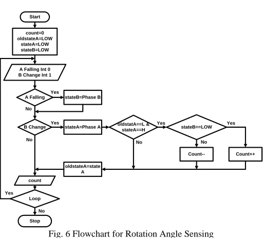
For clockwise direction, Phase B leads than A. The interrupt watching attached to Phase B will check Phase A condition whenever it changes state LOW to HIGH or HIGH to LOW condition. After Phase A is changed LOW to HIGH condition,
the second interrupt will check Phase B condition. If it noticed Phase B stands at LOW condition, the rotation takes clockwise direction could be determined. This condition is represented as Fig. 4.
B A
LOW HIGH
LOW LOW
Fig. 4 Phase Condition for Clockwise Direction
For counter clockwise direction, Phase A leads than B. The interrupt watching attached to Phase B will also check Phase A condition whenever it changes state LOW to HIGH or HIGH to LOW condition.
Fig. 5 Phase Condition for Counter Clockwise Direction
Start
count=0 oldstateA=LOW
stateA=LOW stateB=LOW
A Falling Int 0 B Change Int 1
A Falling stateB=Phase B
B Change stateA=Phase A oldstatA==L &
stateA==H stateB==LOW
Count++
Count--oldstateA=state A count
Loop
Stop
Yes Yes Yes
No No
No No
Yes
No Yes
Fig. 6 Flowchart for Rotation Angle Sensing
After Phase A is changed LOW to HIGH condition, the second interrupt will also check Phase B condition. If it noticed Phase B stands at HIGH condition, we can surely determine that the rotation currently takes counter clockwise direction. This condition can be represented in Fig. 5. These above two consideration method can be represented as following flowchart of Fig. 6.
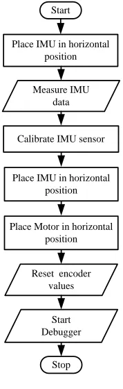
[image:2.612.73.258.420.619.2]data collecting. Fig. 7 mentions initialization program flow chart for this setup.
Start
Stop Place IMU in horizontal
position Measure IMU
data
Calibrate IMU sensor
Place IMU in horizontal position
Place Motor in horizontal position
Reset encoder values
Start Debugger
Fig. 7 flowchart for real-time debugger setup
IV. IMUSENSORFUSION
A. IMU sensor
GY-80 module mounted with axis accelerometer and 3-axis gyroscope is used to fuse sensing data using I2C protocol. This board combines five sensors into a single package and all sensors are all accessible using I2C communication. Among them ADXL345 accelerometer and L3G4200D gyroscope is used for this research work.
The ADXL345 is a small and it uses ultralow power. It can senses three axis with high resolution (13-bit) measurement at up to ±16 g. Digital output data of ADXL345 is formatted as two 8-bits register and it is accessible through either a SPI (Serial Peripheral Interface) or I2C interface. This is well suited for mobile devices and portable conditions. It measures the static acceleration of gravity in inclination or declination sensing applications, as well as dynamic acceleration resulting from motion or shock. It has a high resolution (3.9 mg/LSB) for inclination changes less than 1.0°.
X
Y Z
Ɵ Ψ
ɸ
X
Z
[image:3.612.123.212.81.361.2]Y
Fig. 8 Roll, Pitch and Yaw Angles of Inclined Object
The following equation can give
Roll (θ) - Angle of rotation along the X axis Pitch (ψ) - Angle of rotation along the Y axis
Yaw (Φ)- Angle of rotation along the Z axis. Fig. 8
represents tilt angles of inclined object.
Ɵ= atan (�𝐴𝑦𝐴𝑥2+𝐴𝑧2) (1)
Ψ= atan (�AxAy2
+Az2)
(2)
ɸ= atan (�AxAz2+Ay2) (3)
The L3G4200D is a three-axis angular rate sensor with I2C/SPI serial interface communication. The device has a full scale range of ±250/±500/ ±2000 degree per second. The device can be configured to generate interrupt signal to user by an independent wake-up condition. Gyroscope can detect only angular rate, so the new angle can be get from integrating rate and adding to old angle as follow.
Angle (n)= Angle(n-1)+Rate*dt (4) where dt= sampling period.
B. Complementary Filter
Accelerometer gives the acceleration with respect to the earth reference frame and gyroscope gives angular rate. The output of accelerometer is much nosier than that of gyroscope and gyroscope occurs non-return zero error due to integration. Acceleration can be converted into inclination angles using Euler’s calculation and gyroscope rate can be integrated numerically. Control algorithm of complementary filter is shown in Fig. 9.
Acceleration
(accelerometer) Arctan function Digital Low Pass
Digital High Pass
Velocity
(gyroscope) Numeric Integral
Complementary Filtered Angles
Σ
Σ
Fig. 9 Complementary Filter Representation Diagram
Complementary Filter coefficient α is can be calculated as
α=ττ
+dt (5)
Where τ = Time Constant given by cutoff frequency and dt is
sampling period.
According to the action of human arm, the speed of human
arm and limbs fluctuates between 0 to 7 ms-1. [10] Applying
[image:3.612.46.287.620.720.2]For experimental analysis, the robotic arm is forced using human arm and the applied motor can rotate up to 352 rpm which is much faster than human arm movement speed. It means that motor speed is much enough to represent of human arm movement. For sensing and driving operation, complementary cutoff frequency is chosen 10 Hz which is much faster than human arm angular speed and much slower than motor maximum speed. Experimentally sampling rate of Arduino UNO
for filter execution is 30 ms or 33.33 Hz. Coefficient α is now
0.769.
C. Kalman Filter
The Kalman filter could estimate the state of the system, based on current and previous states. It is more precise than the measurement alone. Generally the accelerometer is in general very noise when it is used to measure the gravitational acceleration since the arm is moving up and down. The problem with the gyroscope is that it drifts over time ant it will start to fall down even it is losing movement speed. [12] It helps to determine that the gyroscope can only be trusted on a short term while the accelerometer on a long term.
The complimentary filter is easy to be used because it just consist of a digital low-pass filter for the accelerometer and digital high-pass filter for the gyroscope readings. But it is not as accurate as the Kalman filter. On the other hand, the complementary filter is less complicated and good for short observation time [3-4].
The Kalman filter operates by producing a optimal estimation of the state of the system based upon the measurements. There are two different noises: the noise of input to the filter called the measurement noise and the noise of the system itself called the process noise.
The Kalman filtering process was implemented for C programming using the following seven steps [12].
1. Estimation the current state based on previous states and
gyroscope measurement
𝑥
�
𝑘|𝑘−1=𝐹𝑥�
𝑘−1|𝑘−1+𝐵θ𝑘̇
In above expression, 𝑥
�
𝑘|𝑘−1=�
𝜃𝜃𝑏
̇ �
is priori state matrixcontaining accelerometer angle θ and gyroscope bias
𝜃
̇
𝑏at the current time k based on the previous state.𝐹=�10 −∆𝑡1 � is the state transition model. The term 𝑥
�
𝑘|𝑘−1 represents the previous state.B is the control input model which is defined as𝐵=
�∆𝑡0� and multiply by gyroscope rateθ
̇
̇𝑘.Simplify this stage give the following relation in C programming. At the program starts, rate and bias must be reset.
𝑎𝑛𝑔𝑙𝑒 +=𝑟𝑎𝑡𝑒(𝑛𝑒𝑤𝑟𝑎𝑡𝑒 − 𝑏𝑖𝑎𝑠);
2. Estimation the priori error covariance matrix based on
previous error covariance matrix 𝑃𝑘|𝑘−1=𝐹𝑃𝑘−1|𝑘−1𝐹𝑇+𝑄𝑘
In above expression, 𝑃𝑘|𝑘−1 is a priori error covariance matrix which is calculated from 𝑃𝑘−1|𝑘−1 previous state matrix. According to two type estimation, P is defined as
�
𝑃00 𝑃01𝑃10 𝑃11
�
. 𝑄𝑘 is the current process noise foraccelerometer measurement. F and FT are transport each
other. After solving matrix equations, the following relations for C programming are got.
𝑃00+=𝑑𝑡 ∗(𝑑𝑡 ∗ 𝑃11− 𝑃01− 𝑃10 +𝑄𝑎𝑛𝑔𝑙𝑒);
𝑃01−=𝑑𝑡 ∗ 𝑃11; 𝑃10−=𝑑𝑡 ∗ 𝑃11; 𝑃11+=𝑄𝑏𝑖𝑎𝑠 ∗ 𝑑𝑡;
In above equation, Q-angle and Q-bias can be justified and experimentally implemented in this research work.
3. Computation the difference between the measurement
and the priori state 𝑦
�
𝑘= 𝑍𝑘− 𝐻𝑥�
𝑘|𝑘−1In this expression, 𝑦
�
𝑘 is the difference betweenmeasurement 𝑍𝑘 and priori state 𝑥�𝑘|𝑘−1. The observation
model 𝐻= [1 0] is applied for matrix multiplication. By
C programming language it can be expressed as following. It is applied for Step 6.
𝑦=𝑛𝑒𝑤𝐴𝑛𝑔𝑙𝑒 − 𝑎𝑛𝑔𝑙𝑒;
4. Calculation the innovation covariance Sk
𝑆𝑘 =𝐻𝑃𝑘|𝑘−1𝐻𝑇+𝑅
After inserting previous equations, the following code can be written in C language. R or Rmeasure is the measurement covariance matrix which must be defined by user.
𝑆=𝑃00 +𝑅𝑚𝑒𝑎𝑠𝑢𝑟𝑒;
5. Calculation the Kalman gain
𝐾𝑘= 𝑃𝑘|𝑘−1𝐻𝑇𝑆𝑘−1
𝐾𝑘 =
�
𝐾0
𝐾1
�
Now the gains of Kalman began𝐾0 =𝑃00/𝑆; 𝐾1 =𝑃10/𝑆;
6. Updating the posteriori estimate of the current state
𝑥
�
𝑘|𝑘 =𝑥�
𝑘|𝑘−1+𝐾𝑘𝑦�
𝑘By substitution above equations, new accelerometer and gyroscope angle can be calculated as follows.
𝑎𝑛𝑔𝑙𝑒+=𝐾0∗ 𝑦;
𝑏𝑖𝑎𝑠+=𝐾1∗ 𝑦;
7. Updating the posteriori error covariance matrix
𝑃𝑘|𝑘 = (𝐼 − 𝐾𝑘𝐻)𝑃𝑘|𝑘−1
For temporary usage and updated matrix will form as followings.
𝑓𝑙𝑜𝑎𝑡𝑃00𝑡𝑒𝑚𝑝=𝑃00;
𝑓𝑙𝑜𝑎𝑡𝑃01𝑡𝑒𝑚𝑝=𝑃01;
𝑃00−=𝐾0∗ 𝑃00_𝑡𝑒𝑚𝑝;
𝑃01−=𝐾0∗ 𝑃01_𝑡𝑒𝑚𝑝;
𝑃10−=𝐾1∗ 𝑃00_𝑡𝑒𝑚𝑝;
For most of IMU sensor such as ST L3FD20 3-axis digital output gyroscope, ST LSM303DLHC MEMS system, the following coefficients are used for Kalman filtering. Most of test used STM32 high performance microcontroller. [3]
Q_angle = 0.001 Q_gyroBias = 0.003 R_measure = 0.03
In this research work, low cost sensor and controller are used and it is not sure the above coefficients are still useful or not. So a practical observation on above coefficients will be discussed on coming section.
D. IMU Sensor Fusion
Functional block diagram is shown in Fig. 10. At first, program needs to check interrupt signal changes which is attached to A and B phase of Quadrature Encoder. Then, it is required to record time in milli-second. And then acceleration and gyroscope rate are measured. Moreover, the calculation using arctan function for acceleration and recording new milli-second time is preceded consequently. The time interval is calculated by subtracting old milli-second record from new one because the time stamp is increasing in every milli-second. For getting changes in one second rate, this time interval is divided by 1000 because gyroscope can give changes in one second only. Multiplying these rate and time interval gives the angle changes. By adding these angle changes to old angle, the inclination angle can be recorded. The complementary filtering will perform using predefined coefficient of 0.679 for low-pass and high-pass operations. According to the literature review, this coefficient is not different for experimental tests compared to design process [5-6]. So in this work, Kalman coefficients will be emphasized. After performing Kalman filtering, old angles are needed to replace with new angle for gyroscope rate calculation for next program sequence.
Start
Init Serial, I2C and Interrupts
New encoder count
E_Angle=count*0.8823
Record Start Time
(ms)
Measure acc angle and
gyro rate
Perform Complementary and Kalman filter
Record End Time (ms) and update results dt=(End time-Start time)/
1000
Export to Serial Monitor
Observe again
End Yes
Yes No
[image:5.612.317.572.151.302.2]No
Fig. 10 Flowchart of Complementary Filter Process
As the heart of the system Arduino UNO board is used. 115200 baud rate is applied for serial communication to PC as shown in Fig. 11. The two interrupt channels are used for Quadrature encoder and I2C pins are applied for sensor board with respective address.
Encoder
Arduino UNO 2 (int 0)
3 (int 1)
PC (USB)
Serial to USB
D+
D-D+
D-5V
5V
Vcc GY80
ADXL345 Address 0x53
L3G4200D Address 0x69
A4 (SDA)
A5 (SCL) SDA
SCL
5V 5V
GND
GND
GND GND
Phase A
Phase B
Fig. 11 Overall Block Diagram of the System
V. EXPERIMENTALTESTANDRESULT
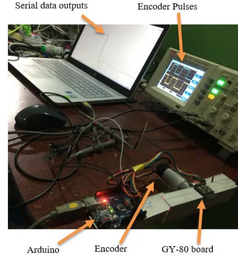
[image:5.612.320.562.428.687.2] [image:5.612.41.303.462.733.2]Experimental setup for the comparison process is shown in Fig. 12. The arm on which GY-80 board is attached and the rotation angle is cascaded with motor encoder. Real time pulses for both of encoder are measured using oscilloscope and precise measurement are displayed on PC.
Fig. 12 Experimental Setup for Comparison Process
The first experiment is done using default Kalman setting. They are
[image:6.612.318.576.56.194.2]float Q_angle = 0.001; float Q_gyroBias = 0.003; float R_measure = 0.03;
Fig. 13 Kalman Filter Test Using Default Setting
This experiment gives the result as shown in Fig. 13. Each
interval of X-axis long for 30 milli-second which is ∆t of
program loop. Although Complementary outputs seem nearly equal to Encoder value, the Kalman outputs differ from Encoder values. It can be clearly seen that the difference between Encoder and Kalman filter is twenty degrees.
B. Experiment II
To reduce the difference between Encoder and Kalman filter, the trust level should be reduced. The measurement
covariance matrix is reduced to 0.001 Rmeasure value. The new
result can be seen in Fig. 14.
At the beginning of the experiment II, the estimation of Kalman filter begins quite accurate. But it goes wore later. The measurement covariance value should be reduced less.
Fig. 14 Experimental Result for Rmeasure Value of 0.001 Change
C. Experiment III
Now the Rmeasure value is reduced to 0.001 and the result
[image:6.612.39.295.92.269.2]curve is shown in Fig. 15.
Fig. 15 Experimental result for Rmeasure value of 0.0001 change
Although the difference between Encoder and Kalman filter becomes narrow, the filter out is noisy as much as the output of
accelerometer. It can be determined that the Qbias should be
increased for more trust in the value of gyroscope.
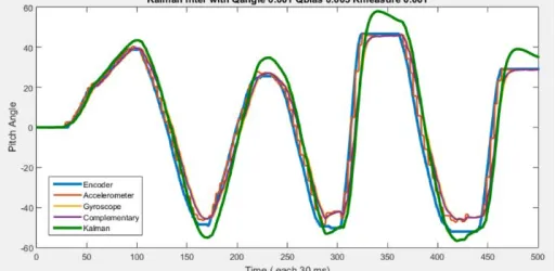
D. Experiment IV
Now the Qbias is increased into the value of 0.1 and the
[image:6.612.317.570.305.441.2]result becomes as shown in Fig. 16.
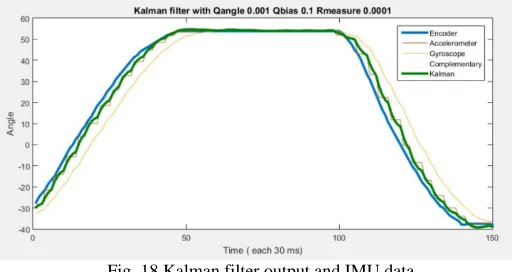
Fig. 16 Experimental result for Qangle value of 0.1 change
Now, the value of Complementary filter and Kalman filter seem closely equal and the comparison should be started.
Now the curve in Fig. 16 are enlarged for X-axis values of 231 to 330 for the following figures. In Fig. 17, the Complementary filter output is closely to gyroscope value and it is big far from actual Encoder value. If its alpha value is decreased, its output would be look like accelerometer value and very noisy.
[image:6.612.41.297.461.586.2] [image:6.612.318.574.570.700.2]Fig. 18 Kalman filter output and IMU data
Fig. 18 shows the Kalman filter output is closely to accelerometer value and it is smooth like gyroscope value. There is small difference with actual Encoder value. It is much better than complementary filter output.
[image:7.612.37.297.335.467.2]Fig. 19 shows the comparison of Complementary and Kalman filter outputs. There is small difference between Kalman filter and actual Encoder value. It is much better than complementary filter output because the Complementary output is much drift as gyroscope output.
Fig. 19 Experimental setup for comparison process
For long term observation, RMSE (Root mean square error) method is used for the above experiments in this research work. This method can be express by using following equation and the results are shown in Table 1.
RMSE=�∑ (encoder(i)-IMU(i))
2 N
i=0
N (6)
TABLEI
RMSE RESPONSE OF COMPLEMENTARY AND KALMAN FILTERS
E x p
Kalman RMSE
Q angle
Q bias
R
meas Acc Gyro Com Kal 1 0.0010 0.0030 0.0300 4.6268 3.9885 3.5689 12.7522 2 0.0010 0.0030 0.0010 4.4061 9.6989 8.2978 10.1673 3 0.0010 0.0030 0.0001 2.5255 5.5820 4.7698 3.2707 4 0.0010 0.1000 0.0001 3.1475 7.8699 6.6629 2.9872
Experiment I points out the bad estimation of Kalman filter which is worse than accelerometer, gyroscope and complementary filter. The value of RMSE error is 12.7522 and it is not acceptable range. But in experiment II, RMSE of Kalman
filter reduced to the value of 10.1673 as decrease Rmeasure
covariance. Experiment III gives lower RMSE error while Rmeasure covariance is reduced to the value of 0.0001. Among
them, experiment IV give lowest RMSE value of 2.9897 which is even half of Complementary filter value. It successfully points out a balance between estimation accuracy in a few milli-second.
VI. DISCUSSIONSANDCONCLUSION
In this research work, a comparative study between two filters were performed using IMU sensor fusion and quadrature encoder techniques, intended to be applied to the estimation of inclination angles of a human interactive robotic arm by experimentally. A compromise choice for filter coefficient with respect to theoretical studies and experimental observation. The experimental results pointed out that Kalman filter can be matched with the accuracy of inclination angle estimation using appropriate filter coefficient based on experimental turning. Moreover it can be clearly seen that the common filter coefficient are not good for estimation. It needs experimental test for low cost sensor and controller. Finally the Kalman based IMU fusion using Qangle as 0.001, Qbias as 0.1 and Rmeasure as 0.0001 shows a
better and compact technique than popular Complementary filter which is less calculation than Kalman. As an advantage, the comparison method used in this research work shows the way of coefficient finding for other types of filters and helps the accuracy checking. The further extension for next step would be expanding the study of inclination angle estimation using other MEMS (Micro-electro-mechanical System) sensors and more appropriate sensor fusion methods.
ACKNOWLEDGMENT
The author would like to thank all the teachers from the Department of Electronic Engineering, Mandalay Technological University (M.T.U). And he also would like to thank his family and his friends who have helped him during this research. And also, thank for Dr. Tin Tin Hla, Head of the department.
REFERENCES
[1] S.A.Quadri and Othman Sidek, “Error and Noise Analysis in an IMU using Kalman Filter”, International Journal of Hybrid Information Technology, Vol.7, No.3 (2014), pp.39-48
[2] Pedro Neto Nuno Mendes A. Paulo Moreira, “Kalman filter-based yaw angle estimation by fusing inertial and magnetic sensing: a case study using low cost sensors”, (2015) Sensor Review, Vol.35 Iss 3pp. 244-250 [3] A. Cavallo, A. Cirillo, P. Cirillo, G. De Maria, P. Falco, C. Natale, S.
Pirozzi, “Experimental Comparison of Sensor Fusion Algorithms for Attitude Estimation”, International Federation of Automatic Control Cape Town, August 24-29, 2014
[4] Fakhri Alam, Zhou ZhaiHe, and Hu JiaJia, “A Comparative Analysis of Orientation Estimation Filters using MEMS based IMU”, 2nd International Conference on Research in Science, Engineering and Technology (ICRSET’2014), March 21-22, 2014 Dubai (UAE)
[5] Gonzalo F. Perez Paina, David Alejandro Gaydou, Claudio José Paz and Luis Canali, “Experimental comparison of Kalman andcomplementary filter for attitude estimation”, Conference Paper August, 2011
[6] Walter T. Higgins, "A Comparison of Complementary and Kalman Filtering", IEEE Transactions on Aerospace and Electronic Systems ( Volume: AES-11 , Issue: 3 , May 1975 )
[8] B. Delporte, L. Perroton, T. Grandpierre, J. Trichet, “Accelerometer and Magnetometer Based Gyroscope Emulation on Smart Sensor for a Virtual Reality Application”, Sensor and Transducers Journal, 2012
[9] S. O. H. Madgwick and A. J. L. Harrison, “Estimation of IMU and MARG orientation using a gradient descent algorithm”, IEEE International Conference on Rehabilitation Robotics Rehab Week Zurich, ETH Zurich Science City, Switzerland, (2011) June 29 - July 1, 2011
[10] M. ElgendiEmail, “Arm movement speed assessment via a Kinect camera: A preliminary study in healthy subjects”, BioMedical Engineering OnLine paper, Jun, 2014
[11] S. Lee and S. Kim,”A self-recongurable dual-arm system," in IEEE, International Conference on Robotics and Automation, Apr 1991 [12]
http://blog.tkjelectronics.dk/2012/09/a-practical-approach-to-kalman-filter-and-how-to-implement-it/
AUTHORS
First Author – Zaw Min Min Htun, M.Sc Eng (Information Science and Computer Technology), Lecturer, Department of Electronic Engineering, Mandalay Technological University, Republic of the Union of Myanmar, [email protected].
Second Author – Maung Maung Latt, Ph.D (Electronics),
Rector, Technological University (Taungoo),
Third Author – Chaw Myat Nwe, Ph.D (Electronics), Professor, Department of Electronic Engineering, Mandalay Technological University, Republic of the Union of Myanmar, [email protected].
Correspondence Author – Su Su Yi Mon, Ph.D (Electronics), Professor, Department of Electronic Engineering, Mandalay Technological University, Republic of the Union of Myanmar, [email protected].