Free Vibration Analysis of Rotating Composite Box Beam
using GY-521 Accelerometer
P. S. Kachare1, Avinash K. Parkhe2, A. A. Utpat3
1, 2, 3Mechanical Engineering Department, SVERI’s, College of Engineering, Pandharpur
DOI: 10.29322/IJSRP.9.02.2019.p8637
http://dx.doi.org/10.29322/IJSRP.9.02.2019.p8637
Abstract- The importance use of composite materials has been increasing consistently in different industries like civil, mechanical,
aerospace engineering due to their advantageous properties. Rotating beams play an essential role in engineering structures such as turbine blades, airplane propellers, and robot manipulators, helicopter blades.
This study deals with free vibration analysis of composite box beam which is rotating at different rpm. The analysis was carried out by considering the accelerations as output parameters. The experimental has designed and developed to carry out analysis on rotating beams. Also, for accelerations measurement, the setup is developed using GY-521 Accelerometer and Arduino. In this analysis, the accelerometer has kept on the composite beam and rotates it for different rpm. During rotating condition accelerations are taken in three directions (i.e., X, Y, and Z) for each rpm using that proposed setup and are represented in a graphical form to analyze free vibrations for rotating beam by estimating the accelerations.
Also, this study is useful to analyze the behavior of rotating beam in undamaged and damaged condition using the same parameter.
Keywords- Vibration, Accelerations, Composite Beam, Undamaged, Damaged, GY-521 Accelerometer, Arduino.
I. INTRODUCTION
The importance use of composite materials has been increasing consistently in different industries like civil, mechanical, aerospace engineering due to their advantageous properties. Rotating beams play an essential role in engineering structures such as turbine blades, airplane propellers, and robot manipulators, helicopter blades. The experimental study has carried out for the stress-strain analysis using strain data acquisition system along with torsional vibration analysis in dynamic condition of beam [1-5]. In addition to that the free vibration analysis has carried out experimentally & theoretically for thin walled composite beam for their dynamic stability [6-10].
This study deals with free vibration analysis of composite box beam which is rotating at different rpm. The analysis was carried out by considering the accelerations as output parameters. The experimental has designed and developed to carry out analysis on rotating beams. Also, for accelerations measurement, the setup is developed using GY-521 Accelerometer and Arduino. In this analysis, the accelerometer has kept on the composite beam and rotates it for different rpm. During rotating condition accelerations are taken in three directions (i.e., X, Y, and Z) for each rpm using that proposed setup and are represented in a graphical form to analyze free vibrations for rotating beam by estimating the accelerations.
This particular analysis has carried out on both undamaged and damaged condition of the composite beam. Initially, experimentation has carried out in the undamaged condition of the beam and after that beam is damaged by producing crack at different locations like near root, at mid and at the tip. Then the same experimentation has carried out on the damaged beam. Then both acceleration results are represented in a graphical form to analyze the effect of damage on accelerations of the rotating beam for different rpm. Also, this study is useful to analyze the behavior of rotating beam in undamaged and damaged condition using the same parameter.
II. EXPERIMENTAL SETUP FOR ACCELERATION MEASUREMENT
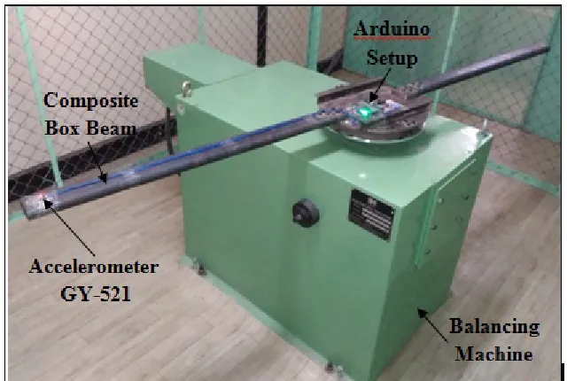
Figure 1 Experimental setup for acceleration measurement using GY-521 Accelerometer ACCELEROMETER GY-52:
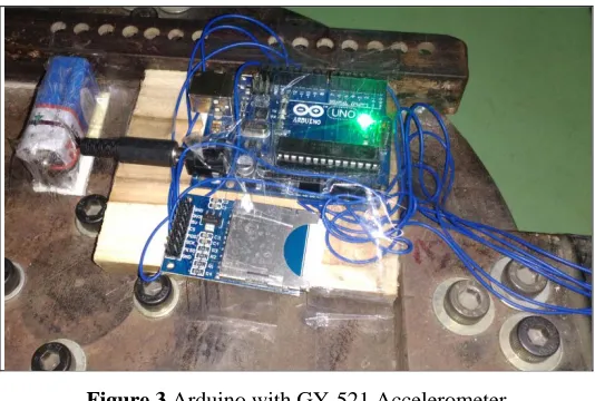
In this analysis, we have developed one accelerometer using GY-521 and Arduino setup for measurement of accelerations in rotating condition. The Gy-521 is mounted on a rotating beam at its free end as shown in figure 2 below and connected with wires to Arduino. It will take 5-volt supply from Arduino.In rotating condition, the GY-521 will capture the accelerations in three directions and this all analog data to Arduino then Arduino will convert that data in digital data and stored it in SD card.
Figure 2 Accelerometer GY-521 ARDUINO SETUP:
[image:2.612.174.440.375.542.2]Figure 3 Arduino with GY-521 Accelerometer
III. ACCELERATION RESULTS FOR ROTATING COMPOSITE BOX BEAM FOR DIFFERENT RPM IN DIFFERENT DIRECTIONS
[image:3.612.188.421.385.448.2]The experimentation was carried out on a rotating composite box beam to measure the accelerations for the different rpm. In this analysis, we have developed the accelerometer using GY-521 and Arduino setup. The above figures show the experimental setup for this particular study. The beam mounted on rotating disk and rotating it for different rpm and using that proposed setup the accelerations are measured. Here we required to find the accelerations of the rotating beam in terms of g value because the direct reading of sensor is not considered as accelerations, we want to make some conversions or calculations to obtain necessary results only. The values obtained from the GY-521 accelerometer or raw values are used to find the ax, ay, az in terms of g value. For our GY-521, acceleration seems to be in the limit of 2g. So, scaling factor = 16384. The scaling factor depends on the acceleration limit. Table 1 shows the scaling factors for acceleration limit as per standards available.
Table 1 Scaling factors for accelerometer values
Acceleration Limit Sensitivity or Scaling factor
2g 16384
3g 8192
4g 4096
5g 2048
Converting the raw data:
Required value or (ax, ay, az) = Sensivity or Scaling factor (in g value)raw value
For example, in the first data, we got,
accel x, y, z: -31203, -1850, -3428
Therefore, from the formula the accelerations are found out by the following way:
ax = −3120316384 g ay = −185016384gaz = −342816384g
ACCELERATIONS IN UNDAMAGED ROTATING COMPOSITE BEAM FOR DIFFERENT RPM:
1.
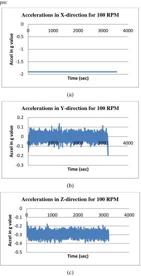
Accelerations for 100 rpm:(a)
(b)
[image:4.612.165.448.61.613.2](c)
Figure 4 Accelerations in three directions for the undamaged beam (100 rpm)
-2 -1.5 -1 -0.5 0
0 1000 2000 3000 4000
Ac
cel
in
g
va
lu
e
Time (sec)
Accelerations in X-direction for 100 RPM
-0.3 -0.2 -0.1 0 0.1 0.2
0 1000 2000 3000 4000
Ac
cel
in
g
va
lu
e
Time (sec)
Accelerations in Y-direction for 100 RPM
-0.5 -0.4 -0.3 -0.2 -0.1 0
0 1000 2000 3000 4000
Ac
cel
in
g
va
lu
e
Time (sec)
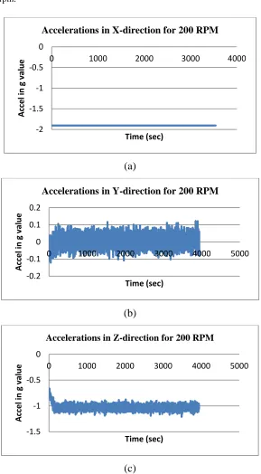
2. Accelerations for 200 rpm:
(a)
(b)
[image:5.612.162.451.65.589.2](c)
Figure 5Accelerations in three directions for the undamaged beam (200 rpm)
-2 -1.5 -1 -0.5 0
0 1000 2000 3000 4000
Ac
cel
in
g
va
lu
e
Time (sec)
Accelerations in X-direction for 200 RPM
-0.2 -0.1 0 0.1 0.2
0 1000 2000 3000 4000 5000
Ac
cel
in
g
va
lu
e
Time (sec)
Accelerations in Y-direction for 200 RPM
-1.5 -1 -0.5 0
0 1000 2000 3000 4000 5000
Ac
cel
in
g
va
lu
e
Time (sec)
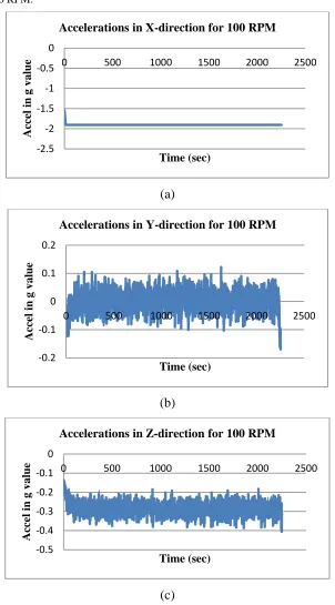
Figure 4, figure 5 shows the accelerations (in g value) in a rotating composite box beam for different rpm and different directions (i.e., X, Y, and Z). The X-direction represents axial direction, Y direction represents the horizontal rotating direction of beam and Z represents the vertical movement of the beam in rotating condition.
ACCELERATIONS IN DAMAGED ROTATING COMPOSITE BEAM FOR DIFFERENT RPM:
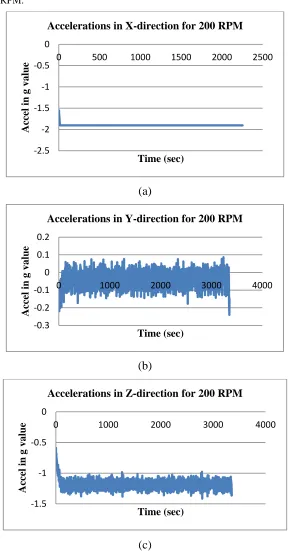
The same experimentation has carried on undamaged to find the accelerations in a rotating beam for different rpm. In this condition, the beam is damage at three locations by producing crack near the root, at mid and at the tip. The results are taken for different rpm and represented in graphical form in three directions such as X, Y, and Z shown in figure 6 & 7.
1. Accelerations for 100 RPM:
(a)
(b)
[image:6.612.155.457.174.719.2](c)
Figure 6Accelerations in three directions for the damaged beam (100 rpm)
-2.5 -2 -1.5 -1 -0.5 0
0 500 1000 1500 2000 2500
A ccel in g v a lu e Time (sec)
Accelerations in X-direction for 100 RPM
-0.2 -0.1 0 0.1 0.2
0 500 1000 1500 2000 2500
A ccel in g v a lu e Time (sec)
Accelerations in Y-direction for 100 RPM
-0.5 -0.4 -0.3 -0.2 -0.1 0
0 500 1000 1500 2000 2500
A ccel in g v a lu e Time (sec)
2. Accelerations for 200 RPM:
(a)
(b)
[image:7.612.161.450.84.635.2](c)
Figure 7Accelerations in three directions for the damaged beam (100 rpm)
-2.5 -2 -1.5 -1 -0.5 0
0 500 1000 1500 2000 2500
A
ccel in
g
v
a
lu
e
Time (sec)
Accelerations in X-direction for 200 RPM
-0.3 -0.2 -0.1 0 0.1 0.2
0 1000 2000 3000 4000
A
ccel in
g
v
a
lu
e
Time (sec)
Accelerations in Y-direction for 200 RPM
-1.5 -1 -0.5 0
0 1000 2000 3000 4000
A
ccel in
g
v
a
lu
e
Time (sec)
IV. RESULT &DISCUSSION
[image:8.612.133.482.132.362.2]From the above all results of undamaged and damaged beam it has that observed that maximum accelerations are produced in the damaged beam. The maximum variations are taking place in the direction of Y. The figure 8 represented the peak to peak variations for undamaged and damaged in Y and Z direction for the different rpm. From this, we can quickly analyze how the system will be disturbed, and maximum accelerations are produced after a damaging beam.
Figure 8 RPM Vs accelerations in the undamaged and damaged beam in Y-direction
Figure 9 RPM Vs accelerations in the undamaged and damaged beam in Z-direction
[image:8.612.130.485.381.624.2]V. CONCLUSION
The above graphical results represented the accelerations in g value for undamaged and damaged rotating composite beam for different rpm. From the above results the following conclusions are drawn:
• If the undamaged beam is rotating for some rpm, then it has observed that there is zero acceleration in the x-direction or axial direction because the beam is rigid at one direction, so there is no any movement will take place in this direction. Also, for all the remaining rpm (i.e. 100 to 500) same results are obtained in x-direction of rotating beam are shown by above figures.
• From the above results in y-direction, it has observed that the maximum accelerations are produced and they are continuously increasing with increases with increase in rpm because in the rotating condition of beam flapping will taking place in the horizontal direction due to this flapping acceleration are produced in this direction.
• For a rotating beam, the vertical movement is also taking place, and this is represented by z-direction. From the above results, it is observed that up to certain rpm the accelerations are produced in z-direction due vertical movement of the beam and after that, there is no any acceleration in this direction for after some rpm.
• From the above all results of undamaged and damaged beam it has that observed that maximum accelerations are produced in the damaged beam. The maximum variations are taking place in the direction of Y. The following graphs represented the peak to peak variations for undamaged and damaged in Y and Z direction for the different rpm. From this, we can quickly analyze how the system will be disturbed and maximum accelerations are produced after damaging beam.
REFERENCES
[1] Ronge, Babruvahan, Prashant Pawar, and Avinash Parkhe. "Experimental analysis of composite rotor blade models for damage identification." In Advances in Science and Engineering Technology International Conferences (ASET), 2018, pp. 1-6.
[2] J. CHUNG, H. H. YOO, “Dynamic Analysis of a Rotating Cantilever Beam by using the Finite Element Method”, Journal of Sound and Vibration, 2002, pp. 147-164.
[3] M. H. Yao, “Nonlinear vibrations of blade with varying rotating speed”, Nonlinear Dynamics, Volume 68, Issue 4, 2012, pp. 487 -504. [4] M. Ohtsuka, “Untwist of Rotating Blades”, Journal of Engineering for Power, Volume 97, Issue 2, 2010, pp. 180-187.
[5] S.A. Sina n, H. Haddadpour, “Axial–torsional vibrations of rotating pretwisted thin walled composite beams”, International Journal of Mechanical Sciences, Volume 80,2014, pp. 93-101.
[6] S. S. RAO, “Finite Element Vibration Analysis of RotatingTimoshenko Beams”, Journal of Sound and Vibration, 242 (1), 2001, pp. 103-124.
[7] Ramazan-Ali Jafari-Talookolaei, Christian Della, “Dynamic behavior of a rotating delaminatedcomposite beam including rotary inertia and sheardeformation effects”, Ain Shams Engineering Journal, Volume 6, 2015, pp. 1031–1044.
[8] Gurkan Sakara, Mustafa Sabuncu,“Dynamic stability analysis of pretwisted aerofoil cross-section bladepackets under rotating conditions”, International Journal of Mechanical Sciences, 50, 2008, pp. 1–13.
[9] S. C. LIN, “Vibration Analysis of a Rotating TimoshenkoBeam”, Journal of Sound and Vibration 240 (2), 2001, pp. 303-322.
[10] Li Jun, Hua Hongxing, “Dynamic stiffness analysis for free vibrations of axiallyloaded laminated composite beams”, Composite Structures 84, 2008, pp. 87–98. [11] B. P. Deepak,RanjanGanguli, “Dynamics ofrotatingcompositebeams:AcomparativestudybetweenCNT reinforced
polymercompositebeamsandlaminatedcompositebeamsusingspectral finiteelements”, International Journal of Mechanical Sciences 64, 2012, pp. 110–126. [12] K.B. Subrahmanyam , K.R.V. Kaza, “Finite difference analysis oftorsional vibrations ofpretwisted, rotating, cantileverbeams with effects of warping”, Journal of
Sound and Vibration, Volume 99, Issue 2, 1985, pp. 213-224.
[13] Thuc Phuong Vo, Jaehong Lee, “Free vibration of axially loaded thin-walled composite box beams”, Composite Structures 90,2009, pp. 233–241.
[14] O.G. McGee, “Influence of warping-pretwist coupling on the torsional vibration of centrifugally-stressed cantilevers with thin-walled open-profile”, Computers & Structures, Volume 42, Issue 2, 1992, pp. 175-195.
[15] Hong Hee Yooa, Jung Eun Chob, Jintai Chung, “Modal analysis and shape optimization of rotatingcantilever beams”, Journal of Sound and Vibration 290, 2006, pp. 223–241.
[16] A. Rosen, “Theoretical and Experimental Investigation of the NonlinearTorsion and Extension of Initially Twisted Bars”, Journal of Applied Mechanics, Volume 50, Issue 2, 1983, pp. 321-326.
[17] C. Martin Saravia, “Free vibration and dynamic stability of rotating thin-walled composite beams”, European Journal of Mechanics A/Solids 30, 2011, pp. 432-441.
AUTHORS
First Author – Dr. P. S. Kachare, PhD (Vibration), SVERI’s, College of Engineering, Pandharpur,[email protected]
Second Author – Mr. Avinash K. Parkhe, ME (Design), SVERI’s, College of Engineering, Pandharpur,[email protected]