Three applications of augmented reality
technologies in structural engineering
education
Whittleston, GS, Haynes, BJ and Mardan, A
Title
Three applications of augmented reality technologies in structural
engineering education
Authors
Whittleston, GS, Haynes, BJ and Mardan, A
Type
Article
URL
This version is available at: http://usir.salford.ac.uk/id/eprint/51072/
Published Date
2018
USIR is a digital collection of the research output of the University of Salford. Where copyright
permits, full text material held in the repository is made freely available online and can be read,
downloaded and copied for noncommercial private study or research purposes. Please check the
manuscript for any further copyright restrictions.
Three Applications of Augmented Reality Technologies in Structural Engineering Education
Gareth Whittleston BEng(Hons), MSc, PhD, PgCertE, FHEA, University of Salford, U.K.
Jonathan Haynes BEng(Hons), MSc, CEng, FIStructE, MICE, PgC, FHEA, University of Salford, U.K.
Alan Mardan BEng(Hons), MSc, PGCAP, FHEA, University of Salford, U.K.
Abstract
In technology terms, a real environment or personal space that is altered with digital media, such as images, is termed Augmented Reality (A.R.). From 2020 onwards, the next big thing in the
technology sector will be A.R. [1]. The purpose of the current paper was to get ahead of the
technology curve and develop applications of A.R. which could be used within structural engineering education both now and in the future. Three applications are presented. The first was a walking map/tour of Manchester and its buildings and bridges, whereby, at each stop, the tour is augmented with explanatory videos showing, amongst other things, structural load paths superimposed onto the actual structure. The second application was a structural engineering laboratory exercise that was augmented with videos explaining how to set up and use the apparatus from start to finish. The intention was to replace Lecturer/Technician assistance and make the exercise self-supporting. The final application used 360o video footage of a real construction site that was augmented with
H&S/C.D.M. information. A unique 360o media suite at the University of Salford was used to display
the video footage, which aided group work and also had a gaming element to the exercise whereby an X-box style controller was used to ‘point and shoot’ at perceived hazards and, if correct, pop ups would be revealed which would give mitigation measures and C.D.M. information.
Quantative and qualitative means were used to measure the effectiveness of each application, with the general conclusion that further and continual refinement of the A.R. content would enhance effectiveness. There were no qualitative comments on the effectiveness of the technology, which implies that participants had few concerns about using the technology. There is promising potential of applying A.R. in structural engineering education in the future.
1. Introduction
The stimulus for looking at augmented reality (A.R.) applications in structural engineering education was initiated through a newspaper article in the Times [1]. The article describes how by 2023 smartphones, so common to the interaction with our digital world, will be supplemented with A.R. glasses. Rather than, head down, thumbing through a 10cm screen interface A.R. glasses would overlay our digital world on top of the real world. Emails, social media, YouTube videos, maps and Satnav applications, to name but a few, could be superimposed onto our reality. Like wildebeest raising their heads when sensing danger in the Serengeti, the populous will be lifting their heads up and away from the tiny screen as digital and real worlds merge into one.
Given that university students in the U.K. are tech-savvy and are open to new technologies, the authors reflected; is there a role for A.R. applications within structural engineering education? In answer to this question, the current paper:
• Discusses potential A.R. applications within Structural Engineering education
• Researches current and available technologies.
• Implements A.R. within structural engineering education and at each level of a U.K. civil engineering undergraduate degree programme.
• Uses a mixture of qualitative and quantative methods to assess the effectiveness of A.R. implementation within a civil engineering degree programme.
2. Current A.R. applications outside of Structural Engineering education.
Mainstream applications of A.R. are commonplace, although we ourselves may not categorise them under “Augmented Reality”. Big-budget movies have altered real footage with digital effects for years. Another common application of A.R. is in sports such as cricket, tennis, rugby, football, and American football where digital images are superimposed on real images to track ball trajectories, player positional movements and gain lines. In some cases, this technology can be used to make on-field decisions through digital review systems.
But what is exciting most techies is personalised A.R. applications. A review of mainstream A.R. applications online can be broadly grouped into the following categories:
[image:3.595.73.275.489.752.2]Navigation. Directions can be superimposed onto real views (see Figure 2.1)
Figure 2.1 A.R. applied to a navigation application [2]
Discovery. The museum of London has introduced Street Museum which turns the city of London into a real museum by geotagging old and significant photographs of London’s history which can only be viewed at specific geographical locations (see Figure 2.2). It uses a smartphone or tablet computer to facilitate.
Gaming. Pokemon Go! [4] was a worldwide A.R. gaming phenomenon, whereby players collect Pokemon characters at specific geographical locations.
Instructional/educational. Several instructional/educational examples have been described in the literature. A useful online article explains some potential e-learning A.R. applications [5]. For illustrative purposes Figure 2.3 visually describes how a traditional text on the anatomy of the human skull can be enhanced with A.R. technology.
Figure 2.3 Augmented medical textbook showing 3D human skull [6]
Advertising/marketing. The largest potential growth of A.R. is possibly through advertising applications. Furniture suppliers have developed A.R. catalogues which, through use of a smartphone can superimpose an item of furniture into your own space (see Figure 2.4)
Figure 2.5 IKEA catalogue furniture superimposed into real space [7].
Most of the applications above use smartphone technology. The majority (if not all) of students on U.K. civil engineering degree programmes possess smartphones. Current A.R. technologies could easily integrate into degree programmes by piggybacking students’ own technological hardware.
3. Potential applications within Structural Engineering education
For Structural Engineering education, A.R. has the exciting possibility of merging something real and physical (like a structure) with an alternative (potentially explanatory) perspective. Any potential applications of A.R. are, of course, limited by available technologies but are also limited by creative idea generation. Creatively speaking, there can be many potential applications of A.R. within Structural engineering education, however several are presented below and which tie-in with the mainstream categories mentioned previously:
1. Supplement traditional lectures of structural concepts and models with explanatory, digital content. [Educational and Instructional]
2. A.R. walking tours which would describe structural load paths of real existing buildings and bridges. [Navigation and Educational and Discovery]
3. Augmenting real/working construction sites with explanatory digital content [Discovery] 4. Practical instructions of structural engineering laboratories [Instructional]
5. Structural engineering textbook with augmented animations of content. [Educational] 6. Merging of construction drawings with real buildings to aid understanding of construction
4. Matching potential applications with education syllabus
The ideas generated were matched with the syllabus of the civil engineering degree programme at the University of Salford, U.K to see which were most feasible. Three suitable applications were chosen which could integrate into the syllabus. These were:
A.R. walking tour could fit into the integrated design exercise module previously described in The Structural Engineer [8]. In this module students were given a project brief to design a complete construction. Projects include sports stadia, airport terminals, exhibition centres and footbridges to name but a few. The students work in project teams and as part of the assessment they are asked to provide three viable alternative schemes which fulfil the brief, two of their schemes have to be creative and original, one has to be an adaptation of an existing project. Students are encouraged to look around their real environment and/or review project based articles in journals such as The Structural Engineer. The A.R. walking tour can be used to supplement their understanding of constructions in their real environment.
An A.R. Laboratory sheet can be integrated into a level HE4 structures module. The structures laboratories form part of the assessment regime on the degree programme at Salford. Laboratories offer a more hands on, physical activity thus more interaction with the real world which gives a better balance between digital and real worlds, Users are less likely to disappear into digital space.
There is also potential to replace laboratory supervision with digital content.
During the Design and Construction Management module at level HE5, students learn about construction management practices, such as project programming, cost management & material procurement, C.D.M., and health and safety risk assessments. This is set in the context of the Constructionarium [9] projects they have to complete. Colloquially, for project programming and critical path analysis, students seem to learn competently enough, with minimal changes before going to Constructionarium. However, C.D.M. with health and safety risk assessments require substantial revision from quite lengthy feedback. When asked, the usual response is that
“We have to put effort into knowing what and when we are going to do specific tasks”
Successful completion of the Constructionarium projects would explain why there is greater
motivation to learn and apply project delivery practices and focus less on C.D.M. and health & safety risk assessments. When quizzed further, the response was
“Health and safety can be dry and boring”
“There are lots of Laws and regulations, but how do I apply it”
Hazard spotting (and how to mitigate their risk) using 360o video footage of a real construction site
to make the subject more interactive and applied would enhance engagement in this part of the syllabus.
5. Available A.R. technologies
Following is the current state of play of A.R. technologies in 2018.
[image:7.595.89.256.209.296.2]In 2013, Google Glass was an initial, pioneering attempt to bring to market an interface product in the form of a glasses headset. Since its launch, it has not been successful in penetrating the mainstream consumer technology market, mainly because of its poor aesthetic appeal and poor functionality [1]. Microsoft have introduced Hololens (Figure 5.1) for gaming aficionados, this unit has better functionality but also suffers from poor aesthetic appeal.
Figure 5.1 Hololens glasses [10]
However, the world’s leading technology giants are developing this technology further, Microsoft, Apple, Google, and even Amazon are developing products for expected release in 2018-19 [1] which are well advanced of Google Glass. All of these products are, unfortunately, not available for use within the current study. But, when they do, finally come to market, the principles contained within this study can be implemented with this technology.
An A.R. product which is currently available is Lifeprint (see Figure 5.2 and [11]).
Figure 5.2 Lifeprint unit featuring a zinc photograph during print
The Lifeprint unit takes video images and converts them into photographic prints of still images onto a special zinc coated film. It uses a smartphone App to allow users to change the still images into video by hovering over the photograph, thus the still image is augmented into video. The
advantages of using this technology within the current study are:
[image:7.595.71.206.430.651.2]• No specialist computers, projectors or technological infrastructure needed other than a smartphone, which is small and portable.
• Mobile native. Apart from the Lifeprint unit no additional technological support is needed because the system piggybacks users’ own technology.
• Relatively inexpensive.
Headsets such as the Vizor virtual reality (V.R.) headset by Red5 (see Figure 5.3) can blur the boundaries between V.R. and A.R. The Vizor V.R. headset uses YouTube 360 on a mobile phone, inserted into the unit, to create an immersive 360o environment.
Figure 5.3 V.R. headset from Red 5
If real 360o video footage is used but augmented with additional information and/or explanatory
animations – is this V.R. or A.R.? It would offer, not a real environment, but a simulated
6. Application One: Architectural and Engineering walking tour of Manchester supplemented using A.R.
6.1 Implementation
From the inception of Application One it was obvious that, currently, the Lifeprint unit would be the most suitable technology to create a walking map of engineering points of interest around
Manchester (Figure 6.1.1). With this technology a map was created with embedded Lifeprint photographs of several buildings and bridges in the city centre. Users could hover their mobile phone over the photos to change them into explanatory videos of each construction.
The choice of route was carefully selected which considered:
• Accessibility (limited amount of steps, limited road crossing points)
• No large walking gaps between points of interest
• Iconic and inspirational constructions
• Variety of structural systems
[image:9.595.73.324.338.715.2]• “Structurally open” constructions where possible.
A description of the route and the information presented in each video now follows. The videos were created using MS PowerPoint and consist of photographs and embedded videos and
explanatory animations with sequenced audio narration. It is important to appreciate that there is a time related delivery to the animations which is lost in the written word. An attempt has been made to communicate the narration and animations with screenshots and present them like a cartoon style storyboard.
1. Manchester bomb (1996) and regeneration of the city centre
[image:10.595.73.362.268.462.2]The Manchester bomb of 1996 started a structured and coherent regeneration of the city centre. Figure 6.1.2 captures some of the images presented in this A.R. video. It shows an image
immediately after the bomb (photo credit G.M.P.) and today. The Figure also shows an image of the Millennium quarter regeneration plan. The coloured regions on the map highlight leisure, retail, offices and residential zones. It was unusual at the time to include residential schemes in such plans.
Figure 6.1.2 Images from the A.R. video on regenration after the 1996 Manchester bomb
The success of the Millennium quarter has led to further development areas such as Spinningfields financial district, The Northern Quarter and N.O.M.A.
2. Urbis building (2002)
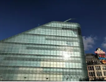
[image:10.595.76.379.607.755.2]The Urbis building (Figure 6.1.3) was part of the Millennium quarter regeneration plan. There was a competition to design the building, whereby the winning entry by Ian Simpson incorporated an urban park/public square into the scheme
The building is unusually shaped, however, the A.R. video explains that behind the façade, the concrete frame is conventionally orthogonal and supports the floors. The curved glazed façade is supported by a steel frame which connects to the main concrete frame.
[image:11.595.76.252.176.307.2]The massing is also unusual. An animation (Figure 6.1.4) describes how most of the mass is on one side - the side closest to the geographical centre of Manchester and the Town Hall. A profiled spire accentuates and points towards the centre as well.
Figure 6.1.4 Animation highlights massing and spire of Urbis building
[image:11.595.74.245.375.507.2]The building is only seven storeys tall. However, the glazing sizes and detailing makes the building appear taller than it actually is (Figure 6.1.5). This resonates with the Flatiron building of New York.
Figure 6.1.5 Storey demarcation given by darker glazing panels. Image shows four panels in-between each storey
The glazing has a few details which can be appreciated up close (Figure 6.1.6). Thick structural silicone joints accommodate any movements in the glazing or supporting steel structure. Again animations add visual texture. A double skin façade can be clearly seen from the street at ground floor level (Figure 6.1.6). An explanation of a double skin façade is given in the A.R. video.
[image:11.595.76.412.618.738.2]3. Sinclair’s Oyster Bar and The Old Wellington Inn (1972)
In contrast to the Urbis building, the next stop on the walking tour was an old, listed building and structural renovation. The technical information of this project is taken from Charge, J. [12]
Originally built in the 15th Century, these two buildings are the last remaining older buildings of
Manchester that were not destroyed by WWII bombing raids. The development of the area in the 1970’s was to include shops and offices which would be serviced by an underground road.
[image:12.595.73.427.249.450.2]Subsequently to retain the old buildings they needed raising 1.46m to accommodate sufficient head clearance to the service road beneath. Figure 6.1.6 shows the buildings in their current state and during lifting operations in the 1970’s (photo credit J Charge)
[image:12.595.74.515.522.735.2]Figure 6.1.6 Sinclair’s oyster bar now and in 1972
Figure 6.1.7 describes the construction sequence through animations of how the buildings were raised.
1. Actually two separate structures. The Old Wellington Inn is of timber framed construction and is on the left. Sinclair’s Oyster Bar is on the right and has load bearing masonry. Both had cellars founded in clay soil, with bedrock approximately 8 metres below the cellars.
2. Steel cross bracing was used to provide stability to the timber frame during lifting
3. The base of the existing structures was underpinned with prop supports. With the ground underneath excavated by hand and accessed via the cellars.
4. Reinforced concrete ground beams, the biggest of which was approximately 2 metres deep, were cast underneath the existing structures.
5. Vertical piers were constructed bit by bit as excavation was undertaken by hand methods down to the bedrock. Jacks were positioned in-between the top of the piers and the underside of the ground beams.
6. Jacks working in unison to raise the structures 1.46m
4. No. 1 Deansgate (2002)
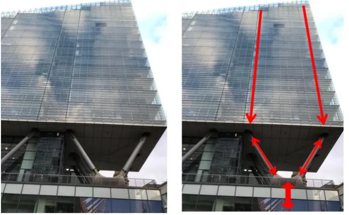
[image:13.595.74.249.391.629.2]This building was part of the Millennium quarter regeneration plan as well. It is a residential block with retail units at ground floor level. Constructed in 2002, the architectural design is such that the residential block appears to float above the retail units below (see Figure 6.1.8)
Figure 6.1.8 No 1 Deansgate
There is some degree of structural openness to this building whereby the central core can be seen from outside, which carries most of the gravity loads. There are also exposed raking columns in-between the residential and retail blocks.
Figure 6.1.9 Animations show how the structural load paths down through the structure using animated arrows.
The A.R. video points out that a double skin façade can be seen externally from certain angles.
5. Trinity Footbridge (1995)
Trinity Footbridge is a cable stayed structure crossing the river Irwell which was designed by
Santiago Calatrava. One bank of the river is higher than the other at its location – hence the curved approaches on one side. It has a mast inclined at 60o. Figure 6.1.10 shows a sketch of the bridge.
[image:14.595.72.350.506.704.2](Photo credit Tzonis, A. and Caso Bonadei, R. [13])
Figure 6.1.10 Schematic of the Trinity footbridge clearly showing layout of cables [13]
Figure 6.1.11 Screenshots of A.R. video before and after animations describing structural load paths.
Next, the structural arrangement of the deck is discussed. The deck is 4 m wide, with the footpath consisting of clay block paving which is supported by a triangular steel box girder. The triangular box girder is, in turn, supported by central cables at regular intervals.
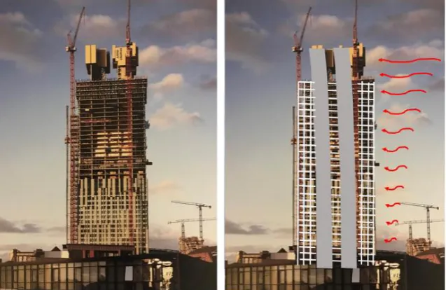
6. Beetham tower (2006)
Currently the tallest building in Manchester. It has a slender footprint which is accentuated by a 4m overhang at the 23rd floor upwards. Below the overhang is a hotel, above residential units.
[image:16.595.75.394.209.416.2] [image:16.595.75.415.516.696.2]Photographs during construction were used in the A.R. video to strip back the external façade to reveal the structural arrangement underneath (Figure 6.1.13). Here, two cores, one servicing the hotel, the other the residential levels are surrounded by reinforced concrete moment frames.
Figure 6.1.13 Beetham tower during construction. Figure also shows, with an animation, how the two cores are assisted by moment frame action to resist lateral wind forces.
On the other hand, Figure 6.1.14 shows how the two cores, which are conventionally concentric, are non-central to help counteract the forces generated by the 4m overhang. Animations are used to show this. An analogy is described in the A.R. video, with a golfer shifting their weight.
Figure 6.1.14 A.R. video screenshots highlighting the 4m overhang of the Beetham tower. Further images show how the cores shift from concentric to eccentric location. Golfer also shown.
7. Manchester Central (1880)
[image:17.595.73.340.131.332.2] [image:17.595.73.339.399.566.2]Manchester Central is a large span structure designed by Sir John Fowler and completed in 1880. It consists of a series of trussed arches which span 64m (see Figure 6.1.15)
Figure 6.1.15 Manchester Central view from side illustrating a series of trussed arches.
It was originally designed as a railway station (see Figure 6.1.16) but was closed in 1969. It was converted into an exhibition centre in 1982.
Figure 6.1.16 Manchester Central in the 1960’s
A.R. videos describe how roof loading is carried through the arch in compression (arch action) to the supports. This is shown in Figure 6.1.17. The arch action generates vertical and horizontal
Figure 6.1.17 A.R. video screenshots before and after animations illustrating arch action.
Support buttresses (Figure 6.1.18) help to provide sufficient horizontal resistance.
Figure 6.1.18 Further screenshot of A.R. video highlighting function of buttresses.
6.2 Measure of effectiveness
The qualitative data was twofold. Firstly, it consisted of a short questionnaire, which asked participants the fundamental questions; what was good? What was bad? And how could the A.R. walking tour be improved?
Secondly, a qualitative assessment of the work produced in the integrated design exercise module was evaluated for the existing scheme. This evaluation was not based upon a mark or grade but was based upon the students’ description of the structural system for the existing structure. It was also of interest to see whether submissions were centred on existing structures from a journal article, a construction in their real environment, or a construction in their real environment from the A.R. walking tour.
6.3 Analysis and evaluation with future actions.
Selected, qualitative responses from the questionnaires are now given. Following the responses, there are actions to improve the A.R. walking tour.
What was good?
“The photographs of the buildings whilst under construction really helped – you could see what was going on”
Action: Take photographs and videos of schemes currently underway (and in the future) to develop a library of “during construction” media for future use.
“Videos really helped my understanding –the bridge one was good”
Action: Retrospectively, why “the bridge one was good” is unclear. However it is assumed that this is because it is a visually open structure which one can walk around, under and over it. The A.R. video does describe a complete load path from the deck to the box girder, to the cables to the mast to the foundation which might explain the positive response. This point needs further investigation in the next cycle.
What was bad?
“Part on double skin façade was confusing”
Action: Expand/refine the animations on double skin façade. Use the A.R. videos to encourage participants to get up close and personal with specific parts of the building where a double skin façade is clear to see and touch.
What could be improved?
“It could be improved by giving the exact location of where to stand so that it ties in with the videos e.g. knowing which side of the bridge to stand”
Turning to the integrated design exercise module and a qualitative evaluation of the work submitted which describes the structural arrangement of an existing construction, and in particular those submissions considering constructions from their real environment.
Most submissions accurately described the structural response of their structure with correct shear, bending and axial force diagrams under vertical, gravity based loading. However, there was a lack of consideration of lateral stability. Also those that did describe lateral stability systems of steel structures within walls (i.e. braced bays) overlooked bracing within roof trusses.
Action: For each construction on the A.R. walking tour create animations which describe the lateral stability system employed as well as the gravity system. Therefore emphasising the importance of lateral stability and that it needs to be considered every time.
Of the sixteen student groups of the module, four chose existing projects from their real
environment. Of these four, one chose a project on the A.R. walking tour (Manchester Central).
Uptake of real environment projects was disappointing. Maybe journal articles describe the structural systems with clarity and there is less uncertainty than real environment constructions which can be covered up with external facades. Unfortunately, this was the first academic year that the cohort was asked to evaluate an existing, real construction and thus a comparative study with data from previous years is not possible. More research is required.
6.4 Final remark
Once improved, the A.R. walking tour of Manchester will be offered to the Young Members
7. Application two: Structural engineering laboratory instruction sheet using A.R.
7.1 Implementation
At level HE4, there are five laboratory tests (see Figure 7.1.1) which demonstrate different structural concepts:
1. Buckling of struts. A steel strut is subjected to increasing compression loading. Both the load and the lateral deformation at mid-length is measured, which is compared against theoretical equations
2. Torsion of circular shafts. The angle of twist for solid, hollow and hollow with longitudinal split circular bars is measured and compared against theoretical calculations.
3. Pin-jointed frameworks. A jack is used to apply a downwards load at the end of a
cantilevered pin-jointed frame. Strain gauges measure the strains in each member of the frame and converts them into load values. The measured load values are compared against theoretical values calculated using method of resolution of joints.
4. Centroids of area. Several wooden shapes are dressed in paper and suspended from two points. A plumb-bob and string is used to draw the actual centroid of area and then compared against theoretical calculations using first and second moments of area.
[image:21.595.72.565.427.661.2]5. Beam reactions and static equilibrium. An aluminium section is supported on two spring balances. A series of load combinations are applied to the section whereby steel masses are suspended from the section. Static equilibrium equations are used to verify the values measured on the spring balance supports.
Figure 7.1.1 Structural laboratory apparatus at the University of Salford. From Left to right, Buckling of struts, Torsion of circular shafts, Pin-jointed frameworks, Centroids of area, Beam reactions & static equilibrium
Students work in groups of four and undertake one of these per two hour session
to replace Lecturer/Technician assistance during the laboratory sessions with assistance from technology.
The Lifeprint unit was used to add photographs of A.R. videos to the laboratory instruction sheets traditionally used in previous years.
7.2 Measure of effectiveness
An initial study was undertaken to assess a datum level for assistance demand from students undertaking the suite of five structures laboratories. This involved drawing up a tally chart for each of the experiments and every time Lecturer/Technician assistance was sought, one mark was added to the column of that particular experiment. Results for two cycles are given in table 7.2.1
Experiment Cycle 1 assistance demand
Cycle 2 assistance demand
Average (arithmetic mean) assistance demand
Buckling of struts 15 18 16.5
Torsion of circular shafts 9 15 12
Centroids of area 12 15 13.5
Pin-jointed frameworks 14 12 13
Beam reactions and static equilibrium
[image:22.595.140.521.256.402.2]10 8 9
Table 7.2.1 Initial analysis to assess the datum assistance demand of all five structures laboratories.
This initial study was used to choose one of the laboratories to apply A.R. principles. The experiment with highest assistance demand was selected from Table 7.2.1, which was the Buckling of Struts experiment.
A series of 15 second videos were created using the camera function on a smartphone. The videos described the steps needed to complete the Buckling of Struts experiment. An A.R. laboratory sheet (Figure 7.2.1) was created using the Lifeprint unit which embedded A.R. photos within the
Figure 7.2.1 Example of A.R. laboratory sheet used in the current study. The photographs turn into videos when the camera App on a smartphone hovers over them.
Figure 7.2.2 Previous laboratory sheet used for Buckling of struts laboratory
[image:23.595.74.496.399.660.2]The A.R. laboratory instruction sheet was used for the Buckling of Struts experiment for five cycles. Lecturer/Technician availability was the same as in the initial study, and, as before, a tally chart was drawn up to quantify the assistance demand of the experiments. Table 7.2.2 shows the results after implementation of the A.R. laboratory instruction sheet for the Buckling of Struts.
Experiment Cycle 1 assistance demand Cycle 2 assistance demand Cycle 3 assistance demand Cycle 4 assistance demand Cycle 5 assistance demand
Average (arithmetic mean) assistance demand
Buckling of struts 5 4 4 6 9 5.6
Torsion of circular shafts 15 10 17 9 14 13
Centroids of area 11 8 13 9 15 11.2
Pin-jointed frameworks 14 12 15 18 12 14.2
Beam reactions and static equilibrium
9 12 8 11 7 9.4
Table 7.2.2 Analysis of assistance demand using the A.R. lab sheet for the Buckling of struts.
7.3 Analysis and evaluation with future work
Table 7.3.1 compares the average assistance demand for each experiment with and without the A.R. laboratory instruction sheet for the buckling of struts.
Experiment Average (arithmetic mean) assistance demand without A.R. sheet for buckling of struts
Average (arithmetic mean) assistance demand with A.R. sheet for buckling of struts
Buckling of struts 16.5 5.6
Torsion of circular shafts 12 13
Centroids of area 13.5 11.2
Pin-jointed frameworks 13 14.2
Beam reactions and static equilibrium
9 9.4
Table 7.3.1 Comparison of assistance demand with and without the A.R. sheet for the Buckling of struts
From this table it can be deduced that the A.R. laboratory sheet has significantly reduced the assistance demand for the buckling of struts experiment. The other experiments have used the same lab sheet throughout and have maintained similar assistance demand, with the slight variation being attributed to the individual levels of deductive ability within the student cohort.
Experiment Cycle 1 assistance demand Cycle 2 assistance demand Cycle 3 assistance demand Cycle 4 assistance demand Cycle 5 assistance demand Cycle 6 assistance demand Cycle 7 assistance demand Average (arithmetic mean) assistance demand Buckling of struts
3 6 4 4 6 8 5 5.1
Torsion of circular shafts
11 10 19 12 15 14 14 13.6
Centroids of area
8 9 7 12 13 14 10 10.4
Pin-jointed frameworks
15 14 10 15 11 16 11 13.1
Beam reactions and static equilibrium
[image:25.595.67.532.69.305.2]12 7 10 9 9 6 12 9.3
Table 7.3.2 Assistance demand for following academic year (2017-18) with the A.R. laboratory sheet for the Buckling of struts. Other experiments using the traditional laboratory sheets.
Future work will involve creating A.R. laboratory instruction sheets for the other experiment types as well. Qualitative data from questionnaires will be collected
8. Application three: 360o video footage of a real construction site superimposed with health and safety/C.D.M. information
8.1 Implementation
360o video footage shot the previous year at Constructionarium was used to create a series of typical
scenarios which could be used to stimulate engagement with C.D.M. and health and safety risk assessments by creating a contextual H&S hazard spotting exercise.
The Vizor V.R. headset (Figure 5.3) could be used during implementation. However, this is a technology suited to individual use and to facilitate activity within groups, which this module is centred on, an alternative technology available at the University of Salford was used.
The Octave, is an immersive, 360o room which projects images on to screens all around the room – it
[image:26.595.73.496.283.428.2]even has a screen on the floor (see Figure 8.1.1). The Octave has a gaming option whereby an X-Box style controller can be used to interact with the images on the screens.
Figure 8.1.1 The Octave at the University of Salford U.K.
Initially, student groups were subjected to an exemplar scenario of 360o footage shot at
Constructionarium which had been augmented. Students could use the X-Box style controller to ‘point and shoot’ at perceived hazards, and, if correct an A.R. text bubble appears with hazard classifications, mitigation measures and C.D.M. information. The green beam of the X-Box controller and the A.R. text boxes can be seen in Figure 8.1.2.
[image:26.595.75.453.562.721.2]Having been given an idea of how to complete the exercise, further 360o videos, within the context
of students’ own Constructionarium projects, were shown to the cohort, but in groups. The aim was to facilitate an in-group discussion of what types of hazards (both C.D.M. and on-site) may be encountered on-site and considered beforehand. Also what on-site mitigation measures or designer inputs were needed for each of the hazards that were identified.
To create the point and shoot element, a computer application called Sphere (pronounced su-fear) is used. Within this program, hazards needed to be tagged throughout the full length of the 360o
[image:27.595.73.473.291.518.2]video with an overlay which identifies where a particular hazard or object is at a particular time and space. The overlays can be shown within Figure 8.1.3 in green. When the footage is playing within The Octave they are invisible to the eye but are not to the X-Box style controller. The overlays can be particularly time consuming to apply if they are irregularly shaped (like the mobile excavator in Figure 8.1.3), and if the object moves at all during the video footage (again like the mobile
excavator). The overlays need to be in place at every second of the footage as well which, again, increases the time demand.
Figure 8.1.3 Screenshot of Sphere program showing green overlays.
8.2 Measure of effectiveness
Effectiveness was measured through qualitative responses from a questionnaire, which asked participants the fundamental questions; what was good? What was bad? And how could the 360o
H&S exercise could be improved?
8.3 Analysis and evaluation with future actions.
Selected, qualitative responses from the questionnaires are now given. Following the responses, there are actions to improve the 360o H&S exercise.
What was good?
“Fun”
“Enjoyed it”
“Group work was good because we could talk to each other and discuss whether it was a hazard or not”
Action: Based upon the positive comments above, expand 360o video catalogue of construction site
footage.
What was bad?
“Video was too long for the number of hazards we could identify”
Action: Shorten videos to 90 seconds in length. Or, put pause/stop function into X-Box controller to allow students to end activity.
To improve?
“More X-Box controllers”
Action: With the current technological set-up this is not possible. A compromise would be to encourage the group work element and communication within groups during the exercise.
“Make the other videos to point and shoot at hazards”
Action: As described previously it was time consuming to create the A.R. gaming videos. With enough time all the 360o videos will have a point and shoot A.R. gaming element. This will be an
evolutionary process. In the short term, feedback solutions could be made available after completion of the exercise for videos without the gaming element.
“Make the activity count towards my grade”
9. Reflections and recommendations
From the analysis, evaluation and future actions chapters of each of the three applications, it is an obvious recommendation to make that each of the three applications will be refined and put through another research cycle in a process of continual improvement.
The other potential applications within structural engineering education (given in chapter 3) will be revisited to see whether they could be implemented within the civil engineering degree programme at University of Salford.
To assist with both of these points it is recommended that an extensive media library is created of current and future sites under construction thus assisting both refinement and new development.
An obvious conclusion is that students seem to like the interactive “less dry” A.R. activities.
However, what isn’t obvious is what has not been said by students.
During use of the technology, it was observed that there were few (if any) questions on how to use it. The technology element seemed quite natural to all users. A point further emphasised by zero comments on how to use or improve the technology within the responses of the qualitative questionnaires of Application one and three.
This has two implications. Firstly, A.R. technologies were easily accepted by students on a U.K. undergraduate civil engineering degree programme. Perhaps because, the technology used in two of the three applications was their own smartphone. And secondly, any A.R. technologies developed in the future will be similarly well received provided that students have had prior exposure.
10. References
(1) Forston, D. (2017). Visionaries. Apple’s plan to kill the I-Phone. The Sunday Times, 16th
April 2017
(2) https://commons.m.wikimedia.org/wiki/Category:Augmented_reality#/media/File%3ANavit
_Reality_View_next_to_reality.jpg, accessed 21st August, 2017
(3)
https://www.buzzfeed.com/lukelewis/photos-of-londons-past-blended-with-its-present?utm_term=.xikM1VwKr#.exjbKVYdg, accessed 21st August 2017
(4) https://www.pokemongo.com/en-uk/, accessed 12th April 2018
(5) https://elearningindustry.com/augmented-future-elearning-augmented-reality-elearning,
accessed 20th May 2017
(6) https://commons.m.wikimedia.org/wiki/Category:Augmented_reality#/media/File%3AApp_i
Skull%2C_an_augmented_human_skull.jpg, accessed 22nd August, 2017
(7)
https://commons.m.wikimedia.org/wiki/Category:Augmented_reality#/media/File%3AViewAR_BUTLERS_Screenshot.jpg, accessed 22nd August 2017
(8) Currie, N., Haynes, J., Leach, P., Wang, J., and Weekes, L. (2013) Embedding technology in the structures thread of a civil engineering degree, The Structural Engineer Vol 91 (3), IStructE, London
(9) http://www.constructionarium.co.uk/ accessed April 12th 2018
(10)https://commons.m.wikimedia.org/w/index.php?search=Hololens&searchToken=d5ap1xg2l
phuq0api4rzmsro2#/media/File%3ARamahololens.jpg, accessed 22nd August 2017
(11)http://lifeprintphotos.com/, accessed 22nd August 2017
(12)Charge, J. (1972), The raising of the Old Wellington Inn and Sinclair’s Oyster Bar, The Structural Engineer, No 12, Vol 50, IStructE, London.
![Figure 2.1 A.R. applied to a navigation application [2]](https://thumb-us.123doks.com/thumbv2/123dok_us/8682072.874942/3.595.73.275.489.752/figure-r-applied-to-navigation-application.webp)
![Figure 5.1 Hololens glasses [10]](https://thumb-us.123doks.com/thumbv2/123dok_us/8682072.874942/7.595.71.206.430.651/figure-hololens-glasses.webp)