Implementation of Smart Homes and Industrial
Automation System with Secure
Communication over GSM
Fatima Tariq, Mahnoor Rashid, Muhammad N. Khan
*Department of Electrical Engineering, University of Lahore, Pakistan
Copyright © 2015 by authors, all rights reserved. Authors agree that this article remains permanently open access under the terms of the Creative Commons Attribution License 4.0 International License
Abstract
Home automation is method of controlling our house hold appliances, updating the status of lights, fans, motors and other appliances through any remote control device or mobile phones. Their ON/OFF status can be changed according to our desire. On the other hand, in present time, smart phones including android and iPhones are great inventions of technology. The awkwardness of hanging out along with a dedicated remote control device or texting an SMS for the automation purpose has always brought lake of interest in the user’s mind towards using such systems. Therefore, in this activity we are introducing a smart home and industrial automation and surveillance system in which we control our appliances through an application installed in our smart phone which uses the available Global System for Mobile (GSM) features from any remote location within our planet, subject to the availability of GSM network. In other words the cumbersome of carrying dedicated separate remote control device and texting the SMS has been eliminated. For surveillance purpose, we used a Wireless Fidelity (Wi-Fi) camera, which uploads the picture or video streaming instantly in any website or sends it to the personal computer system. On the other hand the same purpose can be achieved by using any available software which could help communicating from any end station to PC. Each of these ideas is discussed in great detail in the paper. The proposed system is low in cost and we can reinstall it in any other location by only minor changes in its core. The proposed research work is very helpful for the layman and also to make life more comfortable and luxurious.Keywords
Home Automation, Industrial Automation, Surveillance System, Android Application, Smart Phones, GSM Features, Wi-Fi Camera1. Introduction
As we all know, the idea of home automation and surveillance system is not new. Because of ease it provides to users for controlling and monitoring their appliances from any remote location, many people has been attracted to it as it gives peace of mind to its users that their properties are secure and in their control, even if they are many miles away from their home or industry. There will not be any need of texting the SMS every time or any other dedicated network infrastructure, because the whole communication is proposed to be done over the available GSM or Wi-Fi network [9, 10].
2. System Hardware Design
Following is the list of components used in the hardware design.
1. GSM Module SIM 300/900 DZ
2. PIC Microcontroller (PIC 16f877A or PIC 18f452) 3. Transistors (C1383)
4. Relays (12v) 5. Opto-couplers
The microcontroller used in this project is an 8 bit microcontroller and all the coding is done in C language. It works on the transistor-transistor Logic (TTL) [11]. TTL is a class of digital circuits built from bipolar junction transistors (BJT) and resistors. It is called transistor–transistor logic because both the logic gating function (e.g., AND) and the amplifying function are performed by transistors. The encrypted information received by the receiving module is serially passed on to the PIC Microcontroller which has information about the encryption key and algorithm. Once the information is decrypted by the Microcontroller, the position of drop down menu and the toggle button is clear to it, so it sends the signal to the respective bit of the port B (To which the appliances are connected through transistors and opto couplers) and that particular appliance is turned on or off [6].
The Receiving module used in this system is either SIM 300 DZ or SIM 900 DZ [3] both belong to ‘SIMCom Wireless Solutions’. The operating voltage ranges from 3.6 to 4.5 volts. For communicating with GSM module few AT Commands are required to be used. The list of AT Commands is depicted in Table 1.
Table 1. AT Commands
Sr. AT Commands The Function of AT Command
1 ATD Dial
2 AT+CGMS Send SMS Message
3 AT+CMSS Send SMS Message from Storage
4 AT+CMGL List SMS Message
5 AT+CMGR Read SMS Message
6 AT+CSCA Service Centre Address
7 AT+CPMS To Choose Storage from ME or SM
8 AT+IPR=0 To Choose Auto Baud Rate
9 AT+CMGF= To Choose PDU Mode or Text Mode
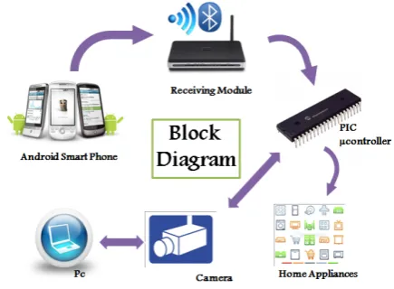
[image:2.595.328.546.221.381.2]As shown in Figure 1, GSM module is serially interfaced with PIC Microcontroller and since both operate on the same TTL logic therefore, there is no need of level shifter or any RS232 protocol to bring the compatibility between them. But for simulation purpose, because of the non-availability of GSM module in Proteus, we had to use a virtual terminal instead of GSM module and for doing the communication between the virtual terminal and Microcontroller, RS232 protocol must be followed and hence we had to use MAX232 [7]. The relays and opto couplers are also used for protection and switching purpose.
Figure 1. Block Diagram of the System
For surveillance purpose, A Wi-Fi or CCTV Camera for capturing and uploading the pictures or video streaming on a dedicated website or PC is used. An alternative approach can also be considered in which we may use any of the already available software for doing the communication between camera and the PC, like Skype or Viber.
3. Security of the System
Unlike the previously implemented such systems, the security of the system has been given a great deal of importance. A three level security authentication is used. First of all, the application is protected via a Password given by the developer of the system, which means that only authorized users will be able to launch the application even if the phone is stolen. And secondly the system at the receiving end verifies that the information it has received is from the authorized user. The user is identified from the mobile number. And lastly, for preventing the system to be operated by sending the information via text messages, the information is encrypted and the key is known to the microcontroller at the receiving end so that it could decrypt the information back. The mode of encryption and the key is kept hidden from the user.
4. Simulation
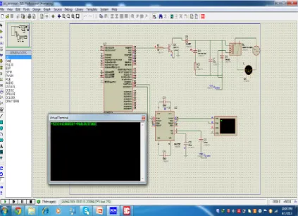
microcontroller compiler like Mikro C or Hi-Tech is loaded in the microcontroller which is connected with a bulb and Hyper terminal through some electronic circuitry, relays and MAX 232 for level conversion. Due to the unavailability of GSM module and smart phone in Proteus, the communication is carried out through Virtual Terminal. The encrypted code is typed in the virtual terminal along with the user’s mobile number for the identification and the information is passed on to the microcontroller through Max232. Here MAX 232 is used under protocol RS232 to give compatibility between TTL logic of microcontroller and RS232 logic of virtual terminal. As soon as the code is typed on the virtual terminal, the bulb attached with the RB0 operates accordingly. The snapshot of the simulation is shown in Figure 2.
5. Development of Application
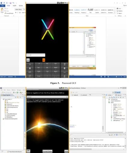
The development of the application is one of the major parts of the proposed system, since it the sole reason which distinguishes the system from previously implemented and available such systems. There were plenty of things which were considered before choosing the appropriate Integrated Development Environment (IDE) amongst the available ones. We choose Eclipse IDE for the application development purpose. There was mainly couple of reasons for choosing this IDE. First of all, it provides ‘Drag and Drop Facility’ for constructing the application layout, as shown in Figure 3.
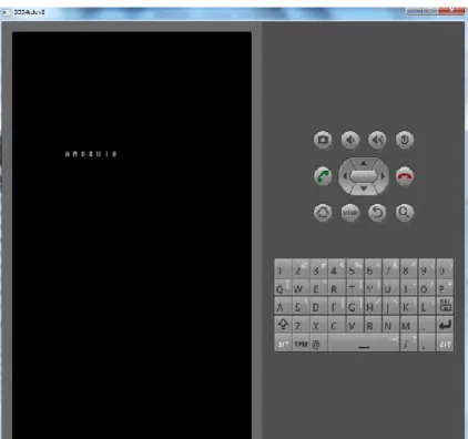
[image:3.595.93.517.312.618.2]Secondly, it provides a Built-in Android Virtual Device (AVD) called ‘Emulator’ for testing the application during the development and troubleshooting purpose. An emulator is a virtual smart phone available in the IDE for testing the application. The snapshot of the Emulator is shown in Figure 4.
Figure 3. Eclipse, Drag and Drop Feature
[image:4.595.94.517.334.730.2]There are two GUI layouts in the application. The first GUI intimates the user for entering the password, as shown in Figure 5.
Figure 5. Password GUI
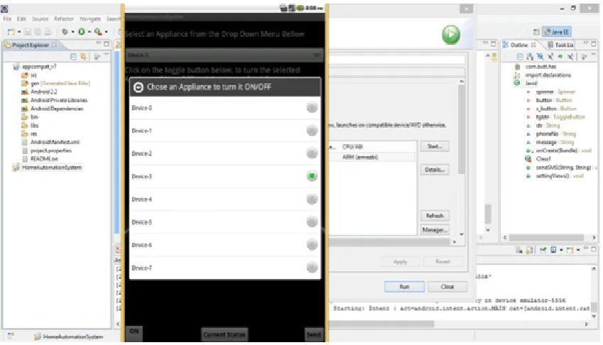
Figure 7. List of Appliances in the drop down menu
After the correct password is entered, a second GUI is displayed, which has the list of all the house hold or industrial appliances in the drop down menu. The user selects the appliance, sets the toggle On/Off button and clicks on send button, as shown in Figure 6 and 7. The user can view the ON/OFF devices from the screen of the mobile which make it more comfortable to make selection of switching the devices. In this way, we can switch ON/OFF any device while driving or sitting in remote areas.
Every time this activity is performed, an SMS is sent to the receiving module containing the encrypted information about the position of selected item in the drop down menu and toggle button, which is decrypted by the microcontroller connected with the receiving module and controller functions accordingly.
6. Conclusions
The system that we presented in this project was a demo, and it can be easily installed in any home, office, apartment or industries. The application and the infra-structure will require some minor modifications. Moreover the surveillance and security of the home might also be accomplished with some more efforts. Unlike previously designed and implemented automation systems there is no burden of carrying the separate remote controller or texting the SMS whenever there is need of switching the appliances. In the hardware implementation of the proposed system, we managed to control eight different appliances from our installed application. Whenever we desire, we can check the current status of our appliances right in our smart phone through a simple operating application. This system is not only for house hold appliances it can be used for industrial automation as well and security of very heavy and expensive machinery. This whole procedure is done through GSM
network. The same communication can be done over Wi-Fi network by using Wi-Fi module instead of GSM module. Similarly a user can get an alert through there smart phone with some sensors installed in the home, like notifications about the fire, alarm, or gas leakage. We are getting more feasibility by installing the proposed system in our homes or in industries. The system cost is very low and the advantages of the system are comparatively very high. By using the proposed system, we can make our life more luxurious and change the way of living.
Acknowledgements
We are very grateful to experts for their appropriate and constructive suggestions to improve this paper.
REFERENCES
[1] Anwaarullah, S., & Altaf, S. (2013). RTOS based Home Automation System using Android International Journal of Advanced Trends in Computer Science and Engineering, 2(1), 480-484.
[2] Axelson, J. The Microcontroller Idea Book: Circuits, Programs & Applications Featureing the 8052-Basic Single-Chip Computer.
[3] Dhawade Pooja, J., Lathkar, Y., Purushottam, SMART HOME USING ANDRIOD APPLICATION.
[5] Panth, S., & Jivani, M. (2013). Home Automation System (HAS) using Android for Mobile Phone. International Journal of Electronics and Computer Science Engineering (IJECSE), 3(1), 1-11.
[6] Kwang Yeol Lee; Jae Weon Choi, "Remote-controlled home automation system via Bluetooth home network," SICE 2003 Annual Conference , vol.3, no., pp.2824,2829 Vol.3, 4-6 Aug. 2003
[7] Low Cost Arduino/Android Based Energy Efficient Home Automation System with Smart Task Scheduling.
[8] Computational Intelligence, Communication Systems and Networks (CICSyN), 2013 Fifth International Conference on [9] Rocha, C., & Botelho, R. Ambient Networks Mobile phone
integration.
[10] An Android Based Home Automation System. High Capacity Optical Networks and Enabling Technologies (HONET-CNS), 2013 10th International Conference on [11] Raspberry Pi Based Interactive Home Automation System