International Journal of Emerging Technology and Advanced Engineering
Website: www.ijetae.com (ISSN 2250-2459,ISO 9001:2008 Certified Journal, Volume 3, Issue 3, March 2013)
294
Design And Analysis of Microcantilevers With Various Shapes
Using COMSOL Multiphysics Software
V. Mounika Reddy
1, G.V.Sunil Kumar
21,2 Department of Electronics and Instrumentation Engineering, Sree Vidyanikethan Engineering College A.Rangampet, Tirupati
Abstract—This paper presents the design, analysis and simulation of MEMS based piezoelectric microcantilevers of
various shapes, to analyse their sensitivity. The
microcantilever beams are made up of single crystal silicon. The analytical simulation of design is done by FEM (COMSOL Multiphysics). The simulation results of applied force and obtained end displacement and electric potential developed are given. The analytical model of the cantilever beam will be analysed and the process of its construction will be discussed. The changes in the sensitivity of a cantilever beam with respect to change in its shape for the same applied force are denoted.
Keywords—MEMS, COMSOL Multiphysics, FEM, Piezoelectric, Cantilever.
I. INTRODUCTION
A cantilever is one which is fixed at one end and the other end is free to move when it experiences some stress. A Microcantilever is a device that can be used as physical, chemical or biological sensor by detecting the changes in cantilever bending or vibrational frequency. It is the miniaturized duplicate of a diving board that moves up and down at regular intervals. This deflection of micro cantilever changes when a specific mass of an analyte is specifically adsorbed on its surface similar to change when a person steps onto the diving board. But the microcantilevers are a million times smaller than the diving board having dimensions in microns and different shapes as shown in figure 1.
[image:1.612.338.553.390.512.2]
Figure 1:Different types of microcantilevers (top view) (a) Rectangular (b) Double-legged (c) Triangular.
These microcantilevers produce a deflection at the free end when a force is applied.
[image:1.612.56.277.552.617.2]As their dimensions are in micrometers and the amount of stress that is applied is also very less, the deflection will also be in micrometers. Hence it becomes extremely difficult to measure the deflection when it is very less. So comparisons have been done by designing the microcantilevers with various shapes and estimate their deflection when the same amount of stress is applied. This enables to find a microcantilever of what shape will have maximum sensitivity. A thin layer of Si [100] was integrated on rectangular SiO2 proof mask cantilever as piezoresistive material. COMSOL Multiphysics, a commercial finite element analysis tool for MEMS was used to develop a finite element model of the SiO2 cantilever.
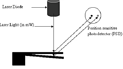
Figure 2: scheme of laser based position detection system.
Detection of deflection caused by the end of the microcantilever beam is done by a PSD (position sensitive detector), which is an optical position sensor(OPS), that can measure a position of the light spot in one or two dimensions on the sensor surface as shown in the figure 2.
Bending of a cantilever beam in response to repulsion and attraction will be as shown in figure 3.
(a) Compressive surface stress due to repulsion between the bio molecules leads to downward/negative deflection of the cantilever beam.
International Journal of Emerging Technology and Advanced Engineering
Website: www.ijetae.com (ISSN 2250-2459,ISO 9001:2008 Certified Journal, Volume 3, Issue 3, March 2013)
[image:2.612.58.277.116.292.2]295
Figure 3:Bending of a cantilever beam in response to compressive and tensile stresses
Uniform surface stress acting on an isotropic material increases (in the case of compressive stress) or decreases (in case of tensile stress) the surface area as shown in figure 3.
If this stress is not compensated at the opposite side of a thin plate or beam, the whole structure will bend. Between the areas of compressive stress and tensile stress, there is a neutral plane which is not deformed.
[image:2.612.340.517.249.376.2]II. DESIGN PARAMETERS OF CANTILEVER BEAM A cantilever is a beam fixed firmly at only one end and left freely at other end. The beam carries the load to the support where it is resisted by moment and stress. The length of the micro cantilever will be much more when compared to its breadth and width as shown in figure 4
.
Figure 4: General structure of a microcantilever
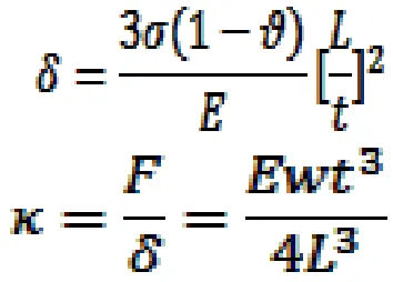
Mainly two equations are important to understand the behaviour of MEMS cantilevers.
Among those two equations first one is Stoney‟s equation, which relates cantilever end deflection „δ‟ to applied stress „σ‟ and it indicates that the end deflection of cantilever beam is directly proportional to the applied stress.
Where „ϑ‟ is Poisson‟s ratio, „E‟ is the Young‟s modulus, „L‟ is the beam length and „t‟ is the cantilever thickness.
The second formula relates the spring constant „
κ
‟ to the cantilever dimensions and material constants:
Where, „F‟ is the force and „w‟ is the cantilever width. The deflection of the cantilever beam depends up on the dimensions of the beam i.e., length, width, thickness and also depends on various properties of the material used to build the cantilever.
The geometric structure of the cantilever beam and also the properties of the material used to construct the shapes of cantilever determine the stiffness of the cantilever. Thus the sensitivity of the cantilever beam changes with the change is shape of the cantilever. The analysis is done on the structure with the following dimensions which is shown in the table 1.
TABLEI
DIMENSIONS
Dimensions
Values
Length
60E-6
Breadth
10E-6
Thickness of cantilever beam
1.5E-6
Thickness of the layer on the beam
[image:2.612.61.268.508.661.2]International Journal of Emerging Technology and Advanced Engineering
Website: www.ijetae.com (ISSN 2250-2459,ISO 9001:2008 Certified Journal, Volume 3, Issue 3, March 2013)
296
This paper demonstrates the finite element method to obtain the optimal performance of SiO2 based microcantilevers sensors by rearranging the dimensions of the cantilever beam to improve the efficiency of the output (sensitivity) of the micro cantilever for the given input (stress applied). A thin beam made up of Si [100] was integrated with rectangular SiO2 proof mask cantilever as piezo resistive material. A commercial finite element analysis tool for MEMS, COMSOL Multiphysics software was used to develop a finite element model of the SiO2 cantilever.
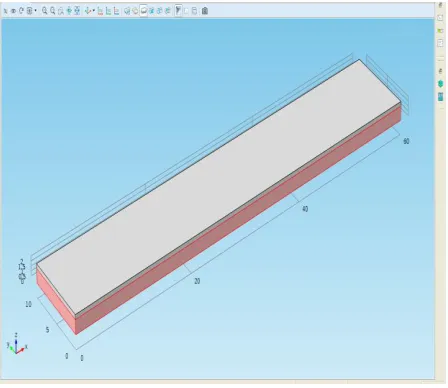
[image:3.612.331.559.231.341.2]Figure 5 shows the view of the microcantilever using piezoelectric devices physics of the structural mechanics application mode of MEMS module of COMSOL MULTIPHYSICS.
Figure 5: View of the design of the microcantilevers.
The structure is made up of silicon single crystal having the properties as shown in the table 2:
TABLE2
CHOSEN MATERIAL PROPERTIES
Material properties: Values
Young‟s modulus 0.2Gpa
Density 2330 kg/m3
Poisson‟s ratio 0.33
The commercial cantilevers are typically made of silicon, polysilicon, silicon nitride, or silicon oxide and are available in a wide variety of different shapes, dimensions, and force sensitivities.
Recent developments combine the latest integrated circuit (IC) and complementary metal oxide semiconductor (CMOS) technologies to produce intelligent extremely small cantilevers in the form of an array.
Silicon dioxide, polysilicon and silicon nitride was used as layer on the Si crystal beam which have the properties as shown in the given table 3:
TABLE3
CHOSEN MATERIAL PROPERTIES WHICH IS USED AS LAYER
Material properties
Material names
SiO2 Si3N4 Poly- Si
Young‟s modulus(Pa)
70E9 250E9 160E9
Density(kg/m3) 2200 3100 2320
Poisson‟s ratio 0.17 0.23 0.22
From the given different material properties literature says SiO2 is the best analysis layer for further simulation due to ease of deposition and etching processes available
III. SIMULATION RESULTS
[image:3.612.55.279.299.493.2]The schematic diagram of the rectangular microcantilever when force applied= 0.5N/m2 is shown in figure 6.
Figure 6: Deformed shape
[image:3.612.332.563.448.626.2]International Journal of Emerging Technology and Advanced Engineering
Website: www.ijetae.com (ISSN 2250-2459,ISO 9001:2008 Certified Journal, Volume 3, Issue 3, March 2013)
[image:4.612.327.577.103.318.2]297
Figure 7: Electric potential
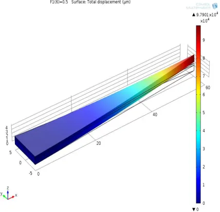
The schematic diagram of the triangular microcantilever sensor is shown in figure 8.
Figure 8: Deformed shape of the triangular shaped beam of microcantilever when force applied= 0.5N/m2
Figure 9 shows the results of the simulation in „slice‟ plot for the electric potential in the triangular shaped microcantilever structure.
[image:4.612.68.283.120.302.2]
Figure 9: Electric potential
[image:4.612.67.281.343.550.2]The schematic diagram of the ∏-shaped microcantilever sensor is shown in figure 10.
Figure 10: Deformed shape of the ∏-shaped beam of microcantilever when force applied= 0.5N/m2
[image:4.612.326.565.362.548.2]International Journal of Emerging Technology and Advanced Engineering
Website: www.ijetae.com (ISSN 2250-2459,ISO 9001:2008 Certified Journal, Volume 3, Issue 3, March 2013)
[image:5.612.317.565.105.306.2]298
Figure 11: Electric potential
[image:5.612.55.290.117.343.2]The schematic diagram of the T-shaped microcantilever sensor is shown in figure 12.
Figure 12: Deformed shape of the T- shaped beam of microcantilever when force applied= 0.5N/m2
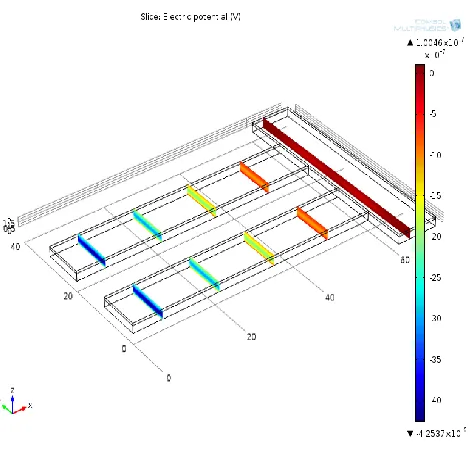
Figure 13 shows the results of the simulation in „slice‟ plot for the electric potential in the T-shaped microcantilever structure.
Figure 13: Electric potential
From the above results it is analysed that the microcantilever of triangular shape has more sensitivity than all other various shaped cantilever beams when same force is applied on all of them.
It is more understood by seeing the comparison table 4.
TABLE4
COMPARISON BETWEEN THE SENSITIVITY CANTILEVER BEAMS OF DIFFERENT SHAPES
STRUCTURE OF MICROCANTILEVER
DEFLECTION OF END IN µM
FORCE APPLIED IN N/M2
RECTANGULAR BEAM 6.335×10⁴ 0.5
TRIANGULAR BEAM 9.7901×10⁴ 0.5
∏-SHAPED BEAM 5.052×10⁻⁶ 0.5
[image:5.612.50.274.392.584.2] [image:5.612.309.577.400.607.2]International Journal of Emerging Technology and Advanced Engineering
Website: www.ijetae.com (ISSN 2250-2459,ISO 9001:2008 Certified Journal, Volume 3, Issue 3, March 2013)
299
IV. CONCLUSION
Microcantilevers of various shapes have been designed and their sensitivity is analyzed when the same amount of force is applied. And it is found that the microcantilever with triangular shape is more preferable as a sensor as it have more sensitivity.
REFERENCES
[1] Suryansh Arora, Sumati, Arti Arora, P.J George, “Design of MEMS based Microcantilever using Comsol Multiphysics”, Applied Engineering Research, Vol.7 No.11, 2012.
[2] Maziar Norouzi, Alireza K, “Design of Piezoelectric microcantilever Chemical Sensor in Comsol Multiphysics Area”, Electrical and Electronics, Vol.2, issue 1,No.184,2009.
[3] Nitin S.Kale,V.Ramgopal Rao,”Design and Fabrication Issues in Affinity Cantilevers for bioMEMS Applications”,Micro Electro Mechanical Systems,VOL.15,NO.6,2006 .
[4] Sandeep Kumar Vashist,”A Review of Microcatilevers For Sensing Applications”, 2007.
[5] Guanghua Wu, Ram H.Datar, Karolyn M.Hasen, Thomas Thundat, Richard J. Cote, Arjun Majumdar,”Bioassay of Prostate-Specific Antigen(PSA) Using Microcantilevers”, Nature Biotechnology, VOL.19, No.856,2001.