© 2018, IRJET | Impact Factor value: 6.171 | ISO 9001:2008 Certified Journal
| Page 3770
Thermal Analysis of Ceramic Coated Piston Head in Diesel Engine
Nishant Varshney
1, Divyansh Mishra
2, Pawan Kumar Agrahri
3, Subhash Gupta
4, Chandan B.B.
5,
Abhishek Kumar
61,2,3,4,6
b.Tech. Department Of Mechanical Engineering, Jss Academy Of Technical Education, Noida, U.P., India
5assistant Professor, Dept. Of Mechanical Engineering, Jss Academy Of Technical Education , U.P.,India.
---***---Abstract
-
The goal of this paper is to determine bothtemperature and stress distributions in a plasma sprayed magnesia-stabilized zirconia coating on an AlSi alloy piston head to improve the performance of a diesel engine. Effects of the coating thickness on temperature and thermal stress distributions are investigated, including comparisons with results from an uncoated piston by means of the finite element method. This paper deals with such type of challenges and can be tackled by coating the piston crown using ceramics. With the help of further analysis using ANSYS on these type of engines, we can increase the thermal efficiency along with reduction of harmful emissions. This project therefore aims at converting conventional engine into Low Heat Rejection engine.
Key Words
: Computer Aided Design (CAD), FunctionallyGraded Material (FGM), Thermal Barrier Coating (TBC), Low Heat Rejection (LHR), Finite Element Analysis (FEA), Convergence Curve (CC), Partial Differential Equation (PDE)
1 .INTRODUCTION
The project deals with the use of thermal barrier coating on the head of the piston so that the temperature inside the chamber increases. The aim is to convert the conventional engine into low heat rejection engine. Hence before on going further there is a need to understand the overview of thermal barrier coatings
.
1.1 Overview of Thermal Barrier Coating
Thermal barrier coatings (TBCs) are commonly applied to substrates to insulate them thermally so as to allow for higher operating temperature. The desire to increase thermal efficiency or reduce fuel consumption of engines makes it tempting to adopt higher compression ratios, in particular for diesel engines, and reduced in cylinder heat rejection. Coating of the diesel engine pistons is one engineering application of TBCs among others. TBCs are applied to insulate combustion chamber components or selected surfaces like the piston crown. Heat rejection is then reduced in the cylinder and the metallic surfaces are protected from thermal fatigue, especially from power and exhaust strokes of the diesel engine cycles. The coating is a ceramic-based material that has low thermal conductivity and good strength is capable of enduring higher temperatures than metals.
The main purpose of this is to raise the temperature of the piston head surface during the expansion stroke, thereby decreasing the temperature difference between the wall and the gas to reduce heat transfer. Some of the additional heat energy in the cylinder can be converted and used to increase power and efficiency. Additional benefits include protection of metallic combustion chamber components from thermal stresses and reduction of cooling requirements. A simpler cooling system will reduce the weight and cost of the engine while improving reliability. There are many potential advantages of low heat rejection (LHR) for engine concepts such as reducing fuel consumption and emissions as well as more durable pistons and exhaust valves.
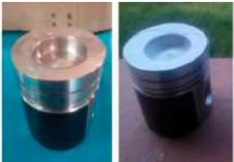
Fig -1: Sample of thermal barrier coated piston head is shown
1.2 Advantages
1. High melting point
2. No phase transformation between room temperature and operation temperature,
3. Low thermal conductivity, 4. Chemical inertness,
5. Thermal expansion match with the metallic substrate, 6. Good adherence to the metallic substrate
7. Low sintering rate of the porous microstructure.
1.3 Low Heat Rejection Engine
[image:1.595.313.554.356.522.2]© 2018, IRJET | Impact Factor value: 6.171 | ISO 9001:2008 Certified Journal
| Page 3771
providing heat resistance in the heat flow to the coolant. The use of coating in the automotive industry has been found to yield a significant effect on the efficiency of engines. The challenge for Automobile is present emission norms that demands engine for green environment with high performance and low emission. The depletion of fossil fuel resources at a faster rate in the present world of economic competitiveness is generating an essential demand for increase in efficiency of internal combustion engines. Higher the operating temperature more will be the efficiency of the system. However, such higher temperatures demand for enhanced temperature resistant materials to be used.
2. LITERATURE REVIEW
Vikrant Garud et. al [1]in the paper depicts experimental investigation is carried out under different loading conditions in a three cylinder diesel engine with its piston crown coated with Yttria Stabilized Zirconia (YSZ) to understand the influence of the thermal barrier coating (TBC) on performance and emission characteristics in comparison with baseline engine characteristics. YSZ is chosen as the candidate material for coating the piston crown because of its desirable physical properties such as high coefficient of thermal expansion, low thermal conductivity, high Poisson’s ratio, and stable phase structure at higher temperature conditions. For the measurement of emission characteristics, ISO 8178-4 ‘‘C1’’ 8 Mode testing cycle procedure is followed. Experimental results revealed that the heat loss to the cooling water is reduced up to 5– 10% and the thermal efficiency is increased by 3–5% with reduction of brake specific fuel consumption by up to 28.29%. Experimental results also revealed that Hydro carbon (HC) emission is reduced up to 35.17%, carbon monoxide (CO) by up to 2.72% and Carbon di-oxide (CO2) emission is increased by up to 5.6%.
Ekrem Buyukkaya [2] in his paper depicts a comparative evaluation between the temperature distributions on the uncoated piston surface and FGM coated AlSi and steel piston surfaces. It has been revealed that the surface temperature of the FGM coated AlSi piston was higher than by 28% that of the uncoated AlSi piston. A similar observation was also made for the steel piston whose temperature rise relative to its uncoated partner was nearly 17%. On the other side, when compared FGM coated two pistons (AlSi and steel), we have seen that the temperature of the steel piston surface was higher by 14% than that of the AlSi piston surface. According to the numerical simulations conducted in this study, it has been concluded that the using of FGM coating for the AlSi and steel pistons increases the temperature of the combustion chamber of the engine, and the thermal strength of the base metal. This is especially the case for the steel pistons. It could also be argued that the cooling load of the engine would decrease accordingly. The temperature values of FGM coating piston surface are lower than traditional thermal barrier coating at the same coating thickness since the increase of the layer number reduces the
thickness of top coat and raises the thermal diffusivity, and thus the heat insulation capability of the coating system gradually decreases.
G. Sivakumar et. al [3]presents a conventional three cylinder diesel engine was converted to a LHR Engine by coating its piston crowns by a 100 μm layer of Yttria Stabilized Zirconia by plasma spray method. Engine parameters, namely brake thermal efficiency, brake specific fuel consumption, power and emission characteristics were measured to investigate the effects of YSZ on its performance and emission characteristics of the engine. The following conclusions can be drawn from the experimental results. The TBC coated engine shows better brake thermal efficiency and better BSFC compared to the baseline engine. Brake thermal efficiency is improved at all loads and speed conditions in the TBC coated engine. The improvement is ranging from 1.14% to a maximum of 8.84% at 50% of full load condition. TBC coated engine reduces the specific fuel consumption by 3.38% and 28.59% at full load and 25% of the full load conditions, respectively when compared to the baseline engine. Hydrocarbon emissions were reduced drastically by 35.27% in the TBC coated engine, whereas Carbon monoxide emission is reduced by 2.7% and Carbon dioxide emission is increased by 5.27%.
M.Srinivasnaik et. al [4]presents the applications of thermal barrier coatings to various components of combustion zone of an engine such as piston and cylinder liner has produced significant improvements in thermal and mechanical efficiency and other performance parameters of the engine like specific fuel consumption and reduces exhaust emission. Thus this paper explores various aspects, effect and application of thermal barrier coating in piston, cylinder liner, SI engine and Diesel engine. So this paper serves as a complete reference guide for the researches who work on coatings for engine applications. The major advantages of thermal barrier coatings for diesel engines are low cetane fuels can be burnt and the valves life-time increases by 300 percent and the overall cost decreases by 20 percent. The decrease in oil consumption is around 15 per-cent. The engine which is the heart of internal combustion engine can be operated 10 percent more than the traditional engine. There will be an increase engine life time by 20 percent the overall fuel consumption decreases by 11 percent. The pollutants emitting out from the exhaust of the automotive vehicles is also increasing due to the increase in the number of vehicles. The main causes of these emissions are: non-stoichiometric combustion, dissociation of nitrogen, solid car-bon particulates. So, the engineers and scientists have to develop engines and fuels of developing very few emissions or no emissions.
© 2018, IRJET | Impact Factor value: 6.171 | ISO 9001:2008 Certified Journal
| Page 3772
top surface of the piston near the flame quenching area is able to increase the temperature from 18% to 48%. However, the degree of thermal insulation on the top surface is constrained with the combustion knocking since the temperature increases extremely at this region. The phenomena are especially observed at full load conditions. Thus, the selection of ceramic materials that cause knocking free operation is very important. The study conducted shows that the temperature distribution on the top surfaces of the standard, Mg-PSZ and Y-PSZ coated pistons are nearly the same apart from coated region.
However, in the case of Mg-PSZ and Y-PSZ, there are sharp increases in surface temperature at the coated regions of the piston compared to standard piston. The results of simulations show that, in SI engines, the use of YPSZ instead of Mg-PSZ as a coating material makes knocking free engines were possible. However, further investigation may be required to examine the coating materials with respect to optimum performance, knocking free operation and lower unburned emissions. The study showed that the engine piston must be designed by selecting the right material selection for considering the constraints described above. Also the performance of the engine with the partially coated piston was improved and HC emissions were extremely decreased, main drawback of Mg-PSZ was the ‘knocking’ which was observed at full load conditions.
Thus, as a future work, the experimental performance results of Y-PSZ coating may be compared with the results of uncoated and Mg-PSZ coated engines.
3. METHODOLOGY
3.1 Plasma Spray Technique
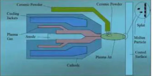
Plasma is a dense gas which has equal number of electron and positive ion and generally named as fourth state of the matter. This method has two primary priorities; it can provide very high temperatures that can melt all known materials and provides better heat transfer than other materials. High operating temperature of plasma spray coating, gives opportunity to operate with metals and alloys having high melting points. Also using plasma spray coating in inert surroundings is another positive side of the method. Oxidation problem of the subject material is reduced due to inert gas usage in plasma spray such as argon, hydrogen and nitrogen. All materials that are produced in powder form and having a specific grain size can be used in this method. The main objective in plasma spraying is to constitute a thin layer that has high protection value over a non-expensive surface. The process is applied as spraying coating material in powder form molten in ionized gas rapidly to coated surface. Plasma spray coating system is shown in Fig. 3.1. The spraying gun is illustrated in Fig. 3.2. The system primarily consists of power unit, powder supply unit, gas supply unit, cooling system, spraying gun and control some layers, an amorphous structure is attained because of fast solidification.
Fig -2: Plasma Spray Gun
Direct current electrical arc is formed between electrode and nozzle in plasma spray coating gun. The inert gas (usually argon) and a little amount of hydrogen gas which is used to empower inert gas mixtures are sent to arc area of plasma gun and heated with electrical arc. Gas mixture temperature reaches to 8300 0C and it becomes ionized. Hence, high temperature plasma beam leaves from gun nozzle. In this system, ceramic grains are supplied to plasma beam as dispersible form. Grains molten by the hot gases are piled up on target surface and hardened. Argon/helium gas mixture increase gas flow and hence ceramic grains speed. Coating layer structure by the plasma spray coating contains equal axial thin solid grains. In some layers, an amorphous structure is attained because of fast solidification .Porosity is a property and a structural indicator of plasma spray coating. By utilizing high viscosity grains and high power plasma units, an intensive coating layer can be attained. Coating layers consisted from brittle and hard ceramic materials have high porosity rates. High porosity negatively affects material hardness which is a mechanical property of the material. While the least porosity layers have about 700 Vickers hardness, porous coating layers have about 300 Vickers hardness. 10 percent of the porosity after plasma spray coating is closed while rest of the porosity is open ones which combined with other defects in the structure because of insufficient fillings of blank areas among settled ceramic grains. Open porosities spoil mechanical properties of substance material by enabling corrosive sediments and gases to diffuse coating layer. On the other hand, spaces parallel to substance surface between layers negatively affect coating adhesion.
[image:3.595.310.559.95.219.2]© 2018, IRJET | Impact Factor value: 6.171 | ISO 9001:2008 Certified Journal
| Page 3773
plasma flame and fixed. Spray powders must hit to target surface perpendicularly to obtain an intensive and good quality ceramic coating .Another important factor is powder size distribution in the spray. Very small grains in the plasma flame can easily reach plasma flame temperature, big grains however, adhere to target surface without being properly molten and make structure to be porous. Researches show that grain sizes between 60 ±10 μm give good results. Plasma spray coating can be conducted either in atmospheric conditions or in vacuum conditions. When it is done in vacuum conditions, plasma flame can expand to 20 cm and more intensive coatings can be obtain. One part of the process parameters which are determined for a specific coating application are depended to operator. To eliminate these parameters effecting coating quality, operating plasma gun with a robot arm or making plasma gun to move vertically and horizontally are proposed as solutions and applied.
3.2 Design of actual problem using design modeller
The first step in the analysis was to develop a mathematical model on a design modeller. We constructed the design on Solidworks 2014.
Meshing is basically discretizing the body into elements and nodes. For meshing a number of tools and softwares are available. To increase the accuracy of solution we have to use denser meshing especially in areas where stress concentration is high like sharp corners or near hole where dense meshing is carried out. In our project, we carried out the meshing on ANSYS 16.0.
In order to find the solution we need to assign certain boundary conditions. In the analysis of thermal performance of internal combustion engine the main conditions were temperature and heat transfer coefficient.
If the error in the analysis is within the prescribed range then the solution is said to be converged otherwise we need to analyse the problem again to meet the convergence criteria.
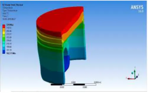
Fig -3: Isometric view of piston
4. DESIGN AND ANALYSIS
4.1 Design Parameters
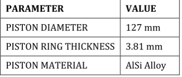
[image:4.595.305.564.102.361.2]The design parameters are given below.
Table -1: Thermal Boundary Conditions
THERMAL BOUNDARY CONDITIONS
TEMPERATURE 0C
HEAT TRANSFER COEFFICIENT
W/m2K
COMBUSTION CHAMBER
650 800
REGION BETWEEN PISTON HEAD AND LINER
300 230
RINGS 85 625
REGION BETWEEN RINGS
110 115
PISTON SKIRT UNDERSIDE
110 717
[image:4.595.328.512.403.481.2]Table -2: Parameters used in the design of piston
4.2 Generation of Mathematical Model
For the same, first a 2D sketch of the drawing was drawn and then it was converted in 3 dimension. The sketch command used to make a circle. Later on this circle was extruded to the length of piston. The cut command was used to make ring groove. Then the mirror command used to make the other ring grooves and saved in .IGES format and transferred to ANSYS 16.0 for further meshing and analysis.
The software Ansys 16.0 was used for analysis purpose. After transferring the .IGES file of the mathematical model, the entire model was broken into quantize number of elements. In the meshing of the mathematical model the number of nodes were 292463 and the number of elements that were 166814. The reason for not opting for a finest match size is to reduce the time taken in the analysis. Secondly finer mesh size leads to use of increased computing power and memory which is not possible on ordinary personal computer. The size of the element is below given is the figure of the messing of model. The elements that are produced during the meshing of the mathematical model are Octahedral. The reason for choosing octahedral mesh shape is that it helps to reduce the error in temperature
PARAMETER VALUE
PISTON DIAMETER 127 mm
PISTON RING THICKNESS 3.81 mm
[image:4.595.36.287.553.674.2]© 2018, IRJET | Impact Factor value: 6.171 | ISO 9001:2008 Certified Journal
| Page 3774
distribution. This shape is better suited for Steady State Thermal Analysis.
Fig -4: Isometric view of meshing
4.3 Temperature Distribution of Various Ceramic Coating
The various thermal barrier coatings are available till present date. .Therefore to choose the thermal barrier coating for further analysis to get the optimized thickness value ,it was first necessary to find out the thermal barrier coating material .First of all the different material coatings of same thickness 0.6 mm were analysed on ANSYS to get the temperature distribution
.
Table -3: Properties of various materials
Material Thermal conductivity
(W/mK)
Density(kg/m3)
AlSi 155 2700
Alumina 92%
26 3720
Alumina 96%
25 3800
FGM(50% MgZrO3+5
0% NiCrAl)
7.3 6543.7
MgZrO3 0.8 5600
The temperature analysis for different coating material is given below:-
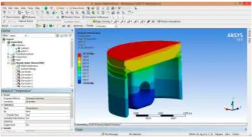
4.3.1 MgZrO3
Fig -5: Temperature distribution with MgZrO3 coating
4.3.2 Alumina 92%
Fig -6: Temperature distribution with Alumina 92% coating
4.3.3:- Alumina 96%
[image:5.595.310.560.107.267.2] [image:5.595.37.287.117.259.2] [image:5.595.309.560.327.485.2] [image:5.595.312.561.544.709.2]© 2018, IRJET | Impact Factor value: 6.171 | ISO 9001:2008 Certified Journal
| Page 3775
4.3.4 FGM (50% MgZrO3 + 50% NiCrAl)Fig -8: Temperature distribution with FGM coating
4.3.5 Uncoated
Fig -9: Temperature distribution with no coating
From the above we came to the conclusion that zirconia based coatings are effective in providing better insulation and hence high temperature is being recorded for MgZrO3 coating.
Now the problem comes to find the thickness, the temperature distribution for various thickness is shown below:-
4.4 Variation of Thickness
Now various thickness are taken and analysed one by one:
4.4.1 Thickness 0.2mm
Fig-10: Temperature distribution with 0.2mm MgZrO3 coating
[image:6.595.308.559.103.239.2]4.4.2 Thickness 0.6 mm
Fig -11: Temperature distribution with 0.6mm MgZrO3 coating
[image:6.595.38.287.107.227.2]4.4.3 Thickness 0.8mm
Fig -12: Temperature distribution with 0.8mm MgZrO3 coating
4.4.4 Thickness 1.2 mm
Fig -13: Temperature distribution with 1.2mm MgZrO3 coating
[image:6.595.38.288.289.407.2] [image:6.595.307.559.308.442.2] [image:6.595.307.560.511.643.2] [image:6.595.36.287.605.724.2]© 2018, IRJET | Impact Factor value: 6.171 | ISO 9001:2008 Certified Journal
| Page 3776
Calculations
The best thickness is identified doing the stress analysis .For it the pressure acting on the piston head is calculated by following equation:
IP = Pm* L* A *N/(2*60) Pressure Required for Calculation of Von Mises Stress is taken out as:
As Per Engine Configuration: IP = 300KW
L= 332 mm D = 127 mm N= 1500 rpm Now,
IP = Pm* L* A *N/(2*60) Pm = 5706.54 Pa Pabs = Patm+ Pm Pabs= 101325+5706.54 Pabs = 107031.54 Pa
The stress analysis according to Von Mises theory for different thickness of coating is given below
:
4.5 Stress Analysis with Variation of Thicknesses
[image:7.595.309.559.104.251.2]4.5.1 Thickness 0.2 mm
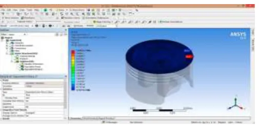
Fig -14: Stress distribution with 0.2mm MgZrO3 coating
4.5.2 Thickness 0.6mm
Fig -15: Stress distribution with 0.6mm MgZrO3 coating
[image:7.595.309.559.307.457.2]4.5.3 Thickness 0.8mm
Fig -16: Stress distribution with 0.8mm MgZrO3 coating
4.5.4 Thickness 1.2mm
Fig -17: Stress distribution with 1.2mm MgZrO3 coating
5. RESULTS
In the present work, analytical investigations are carried out in order to check the fully utilizing fuel in terms of thermal performance of an IC engine .The temperature distribution and stress analysis is carried out by changing the parameters such as coating material, thickness etc., all the parameters being mentioned earlier. A piston with assembly ofcoating was designed on SOLIDWORKS 2014 and then tested on ANSYS 16.0. The ceramic coated piston head are more efficient in terms of specific fuel consumption.
[image:7.595.37.290.430.552.2] [image:7.595.36.290.609.736.2]© 2018, IRJET | Impact Factor value: 6.171 | ISO 9001:2008 Certified Journal
| Page 3777
5.1 Results of Temperature distribution of different [image:8.595.313.546.326.567.2]coatings
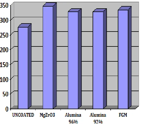
Table -4: maximum temperature for various ceramic coatings
From the above table and graph we came to the conclusion that zirconia based coatings are effective in providing better insulation and hence high temperature is being recorded for MgZrO3 coating .
Now the problem comes to find the thickness, the temperature distribution for various thickness is shown below
Chart -1: Temperature distribution with Different coatings
[image:8.595.38.284.460.678.2]5.2 Results of Temperature distribution of MgZrO3 coating of different thickness
Table -5: Result of Variation in temperature with change in thickness
The graphical representation is depicted below:
Chart -2: Temperature distribution with different MgZrO3 coating thickness
THICKNESS OF MgZrO3
(in mm)
TEMPERATURE OF PISTON HEAD(⁰C)
(maximum temperature)
INCREMENT % (w.r.t.uncoated
piston)
Uncoated 277.16
0.2 339.93 22
0.6 347.26 25.3
© 2018, IRJET | Impact Factor value: 6.171 | ISO 9001:2008 Certified Journal
| Page 3778
5.3 Results of Stress distribution of MgZrO3 coating of [image:9.595.45.277.384.571.2]different thickness
Table -6: Comparison of temperature and stress for various thickness
The graphical representation for stress versus thickness is shown below:
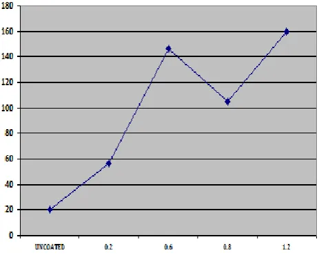
Chart -3: Stress distribution with variation of MgZrO3 coating
The results show that the temperature increases with an increment percentage from 22% at a thickness of 0.2 mm to 39.66% at a thickness of 1.2mm but stress increases from 56.452MPa to 146.48 MPa and then decreases to 104.91MPa for thickness of 0.2mm, 0.6mm and 0.8mm respectively .After that stress increases to 159.82 MPa at a thickness of 1.2mm .Therefore the analysis conducted so far revealed that MgZrO3 coating of thickness 0.8mm gives the best result. The results show that the temperature increases with an increment percentage from 22% at a thickness of 0.2 mm to 39.66% at a thickness of 1.2mm but stress increases from 56.452MPa to 146.48 MPa and then decreases to 104.91MPa for thickness of 0.2mm, 0.6mm and 0.8mm respectively.
After that stress increases to 159.82 MPa at a thickness of 1.2mm .Therefore the analysis conducted so far revealed that MgZrO3 coating of thickness 0.8mm gives the best result.
The analysis showed that minimum stress occurs in case of 0.8mm thickness according to Von Mises theory.
CONCLUSION
This work presented an analytical approach to study the effect of thermal barrier coating on the temperature distribution. The design was developed according to MWM TBRHS 518-V16 diesel engine specifications and model was developed on SOLIDWORKS 2014.The model was transferred to ANSYS where steady state thermal analysis was done. The maximum temperature was recorded for different thermal barrier coatings (TBCs) with varying thickness to decide the material and thickness for ceramic coatings. The AlSi alloy piston has thermal conductivity of 155 W/mK which was coated with coating of MgZrO3, has a thermal conductivity of 0.8W/mK. The coating provides an insulation to the heat rejected and thus increase the temperature inside the combustion chamber and make the fuel combust effectively. The results were plotted for temperature versus coating material, thickness and stress and analysis was done to study the effect. The analysis showed that temperature was increased upto 39.66% for a thickness of 1.2mm zirconia based coating. The stress increases by coating with TBCs but considering overall effect of increment in temperature and stress, the coating with a thickness of 0.8mm was found to be suitable.
A comparative evaluation was made between the temperature distributions on the uncoated piston surface and MgZrO3 coated AlSi piston surfaces. The results showed that the temperature increased with an increment percentage from 22% at a thickness of 0.2 mm to 39.66% at a thickness of 1.2mm but stress increased from 56.452MPa to 146.48 MPa and then decreased to 104.91MPa for thickness of 0.2mm, 0.6mm and 0.8mm respectively .After that stress increased to 159.82 MPa at a thickness of 1.2mm .Therefore the analysis conducted so far revealed that MgZrO3 coating of thickness 0.8mm gives the best result.
FUTURE SCOPE
The scope for further work in the current study is discussed here.
• The performance of the engine can be analyzed using different ceramics and the results could be compared with that of.
• The experimental investigations may be extended to analyze the vibration patterns of the test engine under various modes of operation using different fuel blends. THICKNESS
OF MgZrO3 (in mm)
TEMPERATURE OF PISTON
HEAD(⁰C) (maximum temperature)
INCREMENT % (w.r.t.uncoated
piston)
Max. STRESS
(MPa)
Uncoated 277.16
0.2 339.93 22 56.452
0.6 347.26 25.3 146.48
0.8 368.1 32.81 104.91
© 2018, IRJET | Impact Factor value: 6.171 | ISO 9001:2008 Certified Journal
| Page 3779
• Finite Element Analysis may be employed to assess the distribution of heat and stress developed in the engine for corresponding fuel concentration/compositions.
• A suitable tool/ technique may be identified to optimize the fuel compositions in order to yield the most efficient performance
REFERENCES
[1]Vikrant Garud, Sanjivan Bhiote , Sagar Patil, Suraj Ghadage, Nilesh Gaikwad, Devesh Kute, G. Sivakumar “Performance and Combustion Characteristics of Thermal Barrier Coated (YSZ) Low Heat Rejection Diesel Engine” 5th International Conference Of Materials Processing and Characterization, Vol.4 Issue 2, 2017.
[2]Ekrem Buyukkaya,”Thermal analysis of functionally graded coating AlSi alloy and steel piston” The University Sakarya of Engineering Faculty, Department of Mechanical Engineering, Esentepe Campus, Sakarya 54187, Turkey, Received 8 August 2007
[3]G. Sivakumar, S. Senthil Kumar, “Investigation on effect of Yttria Stabilized Zirconia coated piston crown on performance and emission characteristics of a diesel engine”, School of Mechanical Engineering, Vel Tech University, Chennai 600062, India, Received 18 July 2014
[4]M.Srinivasnaik, Dr.T.V.V. Sudhakar, Dr.B. Balunai,” Low Heat Rejection Engine Coating Materials: A Critical Review”, International Journal of Scientific & Engineering Research, Volume 7, Issue 6, June-2016
[5]Barbara Jankowska-Sieminska, “Some problems pistons made from composite materials with small hysteresis to combustion engines”, Institute of Aviation Warsaw, Poland, 2014.
[6]S. Srikanth Reddy, Dr. B. Sudheer Prem Kumar “Thermal Analysis and Optimization of I.C. Engine Piston Using Finite Element Method”,International Journal of Innovative Research in Science, Engineering and Technology, Vol. 2, Issue 12, December 2013.
[7]Kancharla Raja Sekhar, G. Vijay Prakash “Thermal Analysis of a piston, International Journal of Research in Advanced Engineering Technologies”, Vol.5, Issue 4 October 2016.