International Journal of Emerging Technology and Advanced Engineering
Website: www.ijetae.com (ISSN 2250-2459, ISO 9001:2008 Certified Journal, Volume 3, Issue 5, May 2013)
418
Effect on the Exhaust Gas Temperature, Cooling Water
Temperature and Lubricating Oil Temperature of Single
Cylinder HSDI Diesel Engine by Varying Injection Timing of
MMIS
Nirav M. Bhatt
1, Dr. Pravin P. Rathod
2, Arvind S. Sorathiya
3, Ramesh Patel
41
PG-Student, Mechanical Engineering Department, Government Engineering College-Bhuj
2,3Associate professor Mechanical Engineering Department, Government Engineering College-Bhuj 4Senior Manager-R&D Department, P.M. DIESELS PVT. LTD-Rajkot
Government Engineering College Bhuj-370001 (India)
Abstract— Modern internal combustion engines must meet
high emission standard including better performance and fuel economy. The combustion process in diesel engines is under constant analysis, and during the past decade has drawn increased interest, particularly due to the use of electronically controlled fuel injection systems that enable improved control of combustion in the engine. Multiple injections is a means which can reduce the in cylinder temperature and pressure.
The single cylinder HSDI diesel engine is modified for multiple injections through mechanical injection system. By varying different injection timing, the effect of multiple injections on exhaust gas temperature, lubricating oil temperature and cooling water temperature has been characterized with single time injection.
Better performance of engine with MMIS (Mechanical Multiple Injection System) shows the reduction of engine temperature and is a potential for reduce cooling cost of engine. The engine test cycle is follows as per IS: 10000 (Part VI) – 1980 constant speed of 3000 rpm.
Keywords— MMIS, multiple injection, pilot injection,
HSDI, exhaust gas temperature, cooling water temperature, lubricating oil temperature.
I. INTRODUCTION
Fuel injection has a significant impact on engine operation mode. Diesel engines work with lean mixtures. The engine draws in air and compresses it, and at the late phase of compression, fuel is introduced into the combustion chamber via the fuel injection system. Initiation of injection, injection characteristics, injection pressure, injection direction and the number of injection jets are all parameters that directly affect the combustion in the cylinder and therefore are subjects of continuous research. As mentioned above, the introduction of electronic control units combined with electromechanical actuators has made possible precise control over the injection parameters.
Until a decade ago, only mechanical injection systems could control the injection in diesel engines. Since mechanical actuation is hard to implement at the high frequencies essential for high-accuracy injection, these injection systems provided a good solution for roughly controlling the injection and were responsible for the diesel engine's bad reputation as heavy, noisy and polluting. [06] In this investigation, the effect of modification of cam shaft allows multiple injections of (pilot + main) double injection strategies in small HSDI direct injection diesel engine with constant speed of 3000 RPM are studied.
II. MULTIPLE INJECTIONS
Multiple injections were first proposed in 1937. Currently the advanced common rail fuel system (CRDI), which can perform as many as five injections per stroke, gives rise to this injection strategy’s application for optimum performance and emission reduction in diesel engines.
Multiple injection is defines as injection of predefined amount of fuel into the combustion chamber before main injection of fuel. It is phenomenon related to splitting up single time injection into number of small injection quantity at various crank angles during one combustion cycle. It also maintains more uniform combustion temperatures, leading to cooler engine conditions and lower nitrogen oxide emissions.
III. DELAY PERIOD
International Journal of Emerging Technology and Advanced Engineering
Website: www.ijetae.com (ISSN 2250-2459, ISO 9001:2008 Certified Journal, Volume 3, Issue 5, May 2013)
419
a.Physical delay: - This is the time required for the fuel to mix properly with the air as preparation for combustion. During this period the fuel particles are atomized, mixed with air and vaporized. This can be reduced by using high injection pressure, better turbulence and by multiple injections.
b.Chemical delay: - This is the time between the end of physical delay and the time of ignition. This is the physical property of fuel and it depends upon many chemical characteristic of the fuel.
For mainly C.I. engine, physical delay plays important role then chemical delay. As lower the delay period, better the combustion efficiency. Multiple injection strategies mainly related to reduction of physical delay which gives more uniform heat release rate.
IV. MMIS(MECHANICAL MULTIPLE INJECTION SYSTEM)
In this investigation involves method of multiple injections by modifying conventional mechanical fuel injection system. All conventional mechanical fuel injection system contains a camshaft in which cam lobe profile gives desired profile of motion rectilinear or oscillatory.
In this research work will provides concept of mechanical multiple injection system through multi lobe cam design. By multiple cam lobe design will give multiple injection of fuel. Multi lobe provides stepped vertical motion of fuel pump which will give multiple injection of fuel.
In two lobe of fuel cam, first ascent gives pilot injection then after in predetermined dwell period no fuel injection occur into the combustion chamber and second injection of fuel carried by main lobe gives two times stepped vertical motion to the plunger of fuel pump which inject fuel two times in one combustion cycle.
This method of fuel injection system will eliminate use of electronically operated system for multiple injections and their drawback. These mechanical multiple injection strategy may directly adopt in mass production in industrial aspect without increasing cost of conventional engine manufacturing.
V. EXPERIMENTAL SET-UP AND PROCEDURE
To evaluate the performance and emission characteristics, the specific type of engine used in this project is a single cylinder water cooled HSDI diesel engine. Set-up of the experimental engine and its specifications are listed in Table I. There is a special modification of the engine includes modified cam shaft designed particularly for multiple injection at specific interval of timing.
The engine is couple with a hydraulic dynamometer acting as a variable load system. Various instruments and gauges are use to obtain different measurements. The engine speed measure with the help of digital tachometer. K-Type thermocouple with digital temperature indicator was used to measure exhaust temperature, cooling water as well as lubrication oil temperature. The method of testing engine follows as per IS standard: 10000 (Part VI) – 1980 for constant speed of 3000 rpm.
TABLEI
MAIN CHARACTERISTICS OF THE TESTED HSDI ENGINE PROTOTYPE
Bore (mm) 82
Stroke (mm) 68
Displacement (cm³) 359
No. of cylinder ONE
Compression ratio 18 : 1
Engine R.P.M. 3000
Injection method Direct Injection
Grade of oil SAE20W40
The experimental investigation carried out at different injection timing (28°, 30°, 32°, 34°, 36° CA) before TDC. The engine was tested each injection timing by varying the load 0%, 40%, 60%, 80%, 100%, and 110% over load condition in six steps. Parameters like BSFC, BP, Air flow, Inlet and exhaust gas temperatures, dry/wet bulb temperatures, barometric pressure, cooling water temperature, Lubricating oil temperature has been measure. The instruments used for measurements and there accuracy are listed in Table II.
TABLEII
SPECIFICATIONS OF INSTRUMENTS USED
Sr. No.
Measurement Instrument Accuracy
1 Engine speed Digital
tachometer
±1 rpm
2 Engine load Hydraulic
dynamometer
0.1 N.m
3 Diesel
consumption
Liquid level burette
0.1 ml
4 Lubrication oil
temperature
Thermo couple + transmitter
0.1%
5 Cooling water
temperature
Thermo couple + transmitter
0.1%
6 Exhaust gas
temperature
Thermo couple + transmitter
0.1%
International Journal of Emerging Technology and Advanced Engineering
Website: www.ijetae.com (ISSN 2250-2459, ISO 9001:2008 Certified Journal, Volume 3, Issue 5, May 2013)
420 VI. RESULTS AND DISCUSSION
A. Effect of Brake Power on Exhaust Gas Temperature
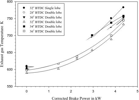
Figure I compare the brake power and exhaust gas temperature. It can be seen from graphs that the exhaust gas temperature increases with the load with varying timing of injection of multiple and single time injections. By comparing multiple injections with base line single time injection shows reduction of exhaust temperature. It is due to the short ignition delay in multiple injection mode lead to completion of combustion process. Total mass of fuel burning inside is divided into two parts which leads to smoother running of combustion cycle.
Corrected Brake Power in kW
0 1 2 3 4 5
Ex
h
au
st g
as T
em
p
er
atur
e K
550 600 650 700 750 800
32o
BTDC Single lobe 28o
BTDC Double lobe 30o
BTDC Double lobe 32o
BTDC Double lobe 34o
BTDC Double lobe 36o
[image:3.612.325.558.141.307.2]BTDC Double lobe
Figure I Effect of Brake Power on Exhaust Gas Temperature
Optimum amount of exhaust gas temperature of 4% decreases observed from multiple injections of 32° advance BTDC at designed load condition. The value of exhaust gas temperature varies from 3.2% to 8.3% decreases at optimum multiple timing of 32° BTDC compare to base line of single time injection.
B. Effect of Brake Power on Lubricating Oil Temperature
Figure II compares the brake power and lubricating oil temperature. It can be seen from graphs that the lubricating oil temperature increases with the increase in load for varying injection timing of multiple injections. Tests results of multiple injections shown in figure have lower value of lubrication oil temperature than base line single time injection.
Corrected Brake Power in kW
0 1 2 3 4 5
Lu
b
ricat
ing
o
il
Tem
p
er
atur
e in
K
330 335 340 345 350 355 360 365 370
32o
BTDC Single lobe 28o BTDC Double lobe 30o
BTDC Double lobe 32o BTDC Double lobe 34o
BTDC Double lobe 36o
BTDC Double lobe
Figure II Effect of Brake Power on Lubrication Oil Temperature
The optimum value of reduction in oil temperature has observed in timing of 32° BTDC at full load condition. There is about 5.3% decrease in lubrication oil temperature compare to base line data at 100% load condition. Optimum multiple injection timing of 32° BTDC has resulted varies from 2.5% to 5.3% decreases observed from all load condition. Because of reduction of combustion temperature in the cylinder there may reduction of lubrication temperature.
C. Effect of Brake Power on Cooling water outlet Temperature
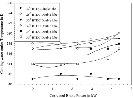
Figure III compares the brake power and cooling water outlet temperature. It can be observed from graphs that the cooling water temperature increases with the load with varying timing of injection of multiple and single time injections. By comparing multiple injections with base line single time injection shows increase of cooling water temperature. It is due to the increase in cylinder temperature in multiple injection modes.
[image:3.612.51.279.289.454.2]International Journal of Emerging Technology and Advanced Engineering
Website: www.ijetae.com (ISSN 2250-2459, ISO 9001:2008 Certified Journal, Volume 3, Issue 5, May 2013)
421
Corrected Brake Power in kW
0 1 2 3 4 5
Co
o
li
n
g
w
ater o
u
tl
er
Tem
p
er
atur
e in
K
310 312 314 316 318 320 322 324 326
[image:4.612.51.279.138.307.2]32o BTDC Single lobe 28o BTDC Double lobe 30o BTDC Double lobe 32o BTDC Double lobe 34o BTDC Double lobe 36o BTDC Double lobe
Figure III Effect of Brake Power on Cooling Water Temperature
VII. UNCERTAINTY ANALYSIS
The present investigation is aimed to measure single cylinder, 4 stroke, HSDI engine performance using multiple injection system with high speed diesel fuel. Moreover, effect of different injection timing of both multiple injection and single time injection is measured. Performance parameters considered are Brake Thermal Efficiency, Volumetric Efficiency, Mechanical Efficiency, Brake Specific Energy Consumption, Brake Specific Fuel Consumption, and Exhaust Gas Temperature.
In order to attain the experimental data some measurements have been made viz. time taken for 50 ml of fuel consumption, fuel quantity, exhaust gas temperature, cooling water temperature, lubrication oil temperature, engine speed, load on engine. These measurements owing to the limitation of the instruments used for the purpose and method employed give rise to some degree of inaccuracy.
TABLEIII
PERCENTAGE AND AVERAGE UNCERTAINTY FOR VARIOUS INJECTION
TIMING
Injection Timing Brake Power
Percentage Range in %
Average in %
32° BTDC Single Lobe 0.031- 0.033 0.032
28° BTDC Double Lobe 0.032- 0.032 0.032
30° BTDC Double Lobe 0.031- 0.032 0.032
32° BTDC Double Lobe 0.032- 0.033 0.032
34° BTDC Double Lobe 0.031- 0.032 0.032
36° BTDC Double Lobe 0.032- 0.032 0.032
Uncertainty is the best estimate of the magnitude of the known error.The methodology of estimating uncertainty in experimental results, employed in the current study, has been suggested by S. Kline et al. [7]. The method is based on careful assessment of the errors associated with primary measurements. Table III shows the percentage range and percent average uncertainty in measurement of brake power.
VIII. CONCLUSION
This study investigated mechanical multiple injections system in diesel engines as a tool for gaining better control of combustion and to decrease combustion emissions. During this research work a special experimental system was designed and built. With this system, a variety of injection timing strategies under low, medium to full loads with different multiple injection timing were tested and characterized. The main findings and observations from the experiments are:
[1] The first injection generates heat, which raises cylinder charge temperature and thus shortens ignition delay time for second injection. Proper use of fuel amount and dwell time of first injection would enable better control over the ignition delay time and the heat release rate of the successive combustion event.
[2] With Mechanical multiple injections, optimum value of exhaust gas temperature of 4% decreases observed from multiple injections of 32° advance BTDC at designed load condition. The value of exhaust gas temperature varies from 3.2% to 8.3% decreases at optimum multiple timing of 32° BTDC compare to base line of single time injection. [3] The optimum value of reduction in oil temperature
has observed in timing of 32° BTDC at 100% load condition. Optimum multiple injection timing of 32° BTDC has resulted varies from 2.5% to 5.3% decreases observed from all load condition.
[4] The cooling water temperature of 2% increase is observed from multiple injections of 36° advance BTDC at 100% load condition. The value of cooling water temperature varies from 4.2% to 7.5% increase at optimum multiple timing of 36° BTDC compare to base line of single time injection.
International Journal of Emerging Technology and Advanced Engineering
Website: www.ijetae.com (ISSN 2250-2459, ISO 9001:2008 Certified Journal, Volume 3, Issue 5, May 2013)
422 REFERENCES
[1] A. J. Davies. ―Injection characteristics and diesel knock‖. Proc. IMechE, Automobile Division, 1951:214-223, 1951.
[2] Badami, M., F. Mallamo, et al. (2003). ―Experimental investigation on the effect of multiple injection strategies on emissions, noise and brake specific fuel consumption of an automotive direct injection common-rail diesel engine.‖ International journal of engine research 4(4): 299-314.
[3] Bakenhus, M. and R. D. Reitz (1999). ―Two color combustion visualization of single and split injections in a single-cylinder heavy duty DI diesel engine using an endoscope based imaging system.‖ SAE paper 1999-01-1112: 1567-1584.
[4] Benajes, J., S. Molina, et al. (2001). ―Influence of pre- and post-injection on the performance and pollutant emission in HD diesel engine.‖ SAE paper 2001-01-0526: 361-371.
[5] Bianchi, G. M., P. Pelloni, et al. (2001). ―Numerical analysis of passenger car HSDI diesel engines with the 2nd Generation of common rail injection systems: the effect of multiple injections on emissions.‖ SAE paper 2001-01-1068: 1099-1117.
[6] Gideon Goldwine, PhD Thesis, ―The Effect of Fuel Injection Profile on Diesel Engine Performance‖ Ben-Gurion University of the Negev, May 2008