International Journal of Emerging Technology and Advanced Engineering
Website: www.ijetae.com (ISSN 2250-2459,ISO 9001:2008 Certified Journal, Volume 3, Issue 3, March 2013)
955
Modeling and Analysis of Piston Rod for Brake Spider Fixture
by Fem Using ANSYS Software
Dr.Yadavalli Basavaraj
1, Pavan Kumar B K
21Professor & Head, 2Asst.Professor, Dept. of Mechanical Engineering. Ballari Institute of Technology and Management,
Bellary. Karnataka
Abstract--A fixture is designed and built to hold, support and locate every component to ensure that each is drilled or machined with accuracy and manufactured individually. A fixture can be designed for a particular job. A brake spider includes a spider body with a central opening and a slot for receiving a camshaft and bracket assembly. The brake spider is attached to axle housing via the central opening.The form to be used depends on the shape and requirement of the work piece to be machined. In the existing fixture, used for modeling brake spider component, only five components were machined per hour. In the present work, detailed study of brake spider component is carried out and design is modified to increase the productivity. The new fixture design is carried out by using CATIA V5 modeling software and it is critically evaluated for the failure of piston rod component, by finite element method (FEM) using ANSYS software. This modified design is adapted in the fabrication of fixture and is tested for its productivity. It is found that there is a considerable enhancement in the productivity to seven components per hour with required accuracy.
KeyWords-- Fixture; piston rod; ansys; brake spider; CATIA V5; FEM
I. INTRODUCTION
Over the past century, manufacturing has made
considerable progress. New machine tools,
high-performance cutting tools, and modern manufacturing processes enable today's industries to make parts faster and better than ever before. Although work holding methods have also advanced considerably, the basic principles of clamping and locating are still the same.
The fixtures must satisfy the following conditions
Reduction of ideal time
Cleanliness
Provision for coolant
Safety
II. LITERATURE SURVEY
A brief review of contemporary research supporting this paper is presented below. The study of Dr. Yu Zheng presents a method for finding form-closure locations with enhanced immobilization capability.
Fixtures are used in many manufacturing processes to hold objects. Fixture layout design is to arrange fixturing elements on the object surface such that the object can be held in form-closure and totally immobilized.
The research of closure locations was determined experimentally by Kartik as it focused on the kinematics, stiffness, repeatability of a moving groove and dual-purpose positioned fixture. A dual-dual-purpose positioned fixture is an alignment device that may be operated in a fixture mode or a six-axis nano-positioning mode.
In contrast to concentration of six axis nano positioning method Dr.Patrick J. Golden tested a unique dovetail fretting fatigue fixture was designed and evaluated for testing turbine engine materials at room or elevated temperatures. Initial test results revealed interesting variability in the behavior of the nickel based super alloy specimens at elevated temperature.
Mervyn addresses the development of an Internet-enabled interactive fixture design system. A fixture design system should be able to transfer information with the various other systems to bring about a seamless product design and manufacturing environment.
The general situation of research on agile fixture design is summarized and the achievements and deficiencies in the field of case-based fixture design are pointed out. There are no correlative case bases and matching mechanisms during the period from establishing the fixture planning to design the fixture in currently used case-based fixture design systems. Thus a great amount of experience of fixture design is wasted and cannot be re-used, which reduces design efficiency and violates the original intention of case-based reasoning methods. In order to realize agility of fixture design, including re-configurability, re-scalability and re-usability.
International Journal of Emerging Technology and Advanced Engineering
Website: www.ijetae.com (ISSN 2250-2459,ISO 9001:2008 Certified Journal, Volume 3, Issue 3, March 2013)
956
The post-buckled beam shows the soften-and-hardening characteristics of restoring force. Inorder to clarify chaotic behavior of thin walled beams, detailed experimental results carried by Nagai are presented on chaotic vibrations of a post-buckled beam subjected to periodic lateral acceleration. The principal component analysis predicts that the contribution of the lowest mode of vibration to the chaos is dominant among other contributions of multiple vibration modes.
K.C. Aw paper concentrates on electronic equipment
used for maritime application. Simulation using ANSYS workbench software was performed to comprehend the effect of various parameters of accelerated testing performed on these waterproof enclosures. Experiments were performed to examine the correlation with simulation results.
The above mentioned strategy was applied to reduce the buckling in a part of fixture design assembly. But our main objective of the project is to increase the productivity with required accuracy.
III. OBJECTIVES
As design of the fixture for the component cannot
happen in isolation, the objective of the project also extends to the aspects like the features of the vertical machining center.
Process planning, cycle time estimation and designing
of the fixture for the brake spider component is carried out.
Critical component of the fixture would be analyzed
from stress and deflection point of view.
IV. METHODOLOGY
Study of the brake spider component and the existing
fixture in use.
Study of the process planning: Estimation of the
process for achieving the final dimensions of the components, selection of tools, tool holders, insert grades, cutting parameters and arriving at the cycle time of the component.
Fixturing concept: As per the fixture base plate
dimensions the vertical machining center is selected and conceptualized design is done by arresting six degrees of freedom by resting, locating, orienting and clamping.
Detailed design: Assembly drawing of the brake
spider fixture using CATIA V5 modeling software.
Analysis of critical components: Static deflection
analysis of key element of fixture piston rod using ANSYS software.
V. FIXTURE DESIGN
Fixture planning is to conceptualize a basic fixture
configuration through analyzing all the available
information regarding the material and geometry of the work piece, operations required, processing equipment for the operations and the operator.
Method of locating.
Design the clamping method.
Design any supports required.
Design the base required.
Design the fixture body.
VI. DESIGN FEATURES
1. Rest
2. Location
3. Orientation
4. Clamp
6.1 Cycle time estimation
The design of fixtures should be such that the process of loading and unloading the components takes the minimum possible time and enables on easy loading.
Table1 Cycle time estimation
Total cycle time
6.40 mins
Load and unload time
2 mins
Total time
8.40 mins
No. of components / hour
7.142 nos.
Hence, the production rate of brake spider component is seven components per hour.
6.2 Fixture planning
Certain things to be remembered while designing a fixture
Application of the fixture
(manufacturing/repair/inspection)
Number of parts for which the fixture will be used
Level of accuracy required
The criticality of the part with respect to the aircraft
Replace ability, reusability and discard ability of the
fixture
International Journal of Emerging Technology and Advanced Engineering
Website: www.ijetae.com (ISSN 2250-2459,ISO 9001:2008 Certified Journal, Volume 3, Issue 3, March 2013)
957
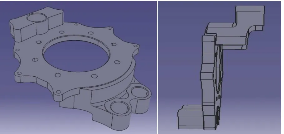
6.3 Brake spider component
A brake spider includes a spider body with a central opening and a slot for receiving a camshaft and bracket assembly. The brake spider is attached to axle housing via the central opening.
[image:3.612.82.536.211.426.2]The slot is defined by an inner surface that does not completely surround the camshaft. The slot allows the camshaft and bracket assembly to be removed from a wheel end assembly for service operations without having to remove other components from the wheel end assembly, such as a wheel hub.
Fig 1: 3D front view and side view model of brake spider component
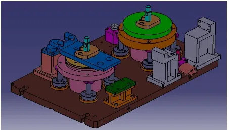
VII. ASSEMBLY OF BRAKE SPIDER FIXTURE
The entire assembly is designed and assembled on the pre-requisites of the customer. The model of the entire fixture assembly in 3D view is shown in Fig 2.
The piston rodof the fixture assembly is bolted onto the
International Journal of Emerging Technology and Advanced Engineering
Website: www.ijetae.com (ISSN 2250-2459,ISO 9001:2008 Certified Journal, Volume 3, Issue 3, March 2013)
[image:4.612.86.539.153.410.2]958
Fig 2: 3D view of brake spider fixture assembly
Stage one deal with information gathering and analysis. These include product analysis such as the study of design specifications, process planning, examining the processing equipment and considering operator safety and ease of use. In this stage, all the critical dimensions and feasible datum areas are examined in detail.
Stage two involves the consideration of clamping and locating schemes. A clamping scheme is devised in such a way that it will not interfere with the tools or cutters and are fully compatible with proposed locating surfaces or areas. The locating scheme, using standard elements such as pins, pads, etc. is designed to be consistent with clamping and tool-guiding arrangements.
Stage three is the design of the structure of the fixture body frame. This is usually built around the as a single element which links all the other elements used for locating, clamping tool-guiding, etc. into an integral frame work.
VIII. INTRODUCTION TO FINITE ELEMENT METHOD
The finite element method is numerical technique, well suited to digital computers, which can be applied to solve problems in solid mechanics, fluid mechanics, heat transfer and vibrations.
The procedure to solve problems in each of these fields is similar in all finite element models of the domain (the solid in solid mechanics problems) is divided into a finite number of elements.
8.1 Basic steps of finite element method
Discretization of the continuum
Selection of key points
Choose proper field variables
Generating the system of equations
Globalizing the system equations
Solution to the system equations to obtain theunknown field variables
Computation of element variable or secondary
field variables
8.2 Introduction to ANSYS
ANSYS is finite element analysis software that enables engineers to perform the following tasks.
Build computer models or transfer CAD models of
structures, products, components, or systems.
Apply operating loads or other design
International Journal of Emerging Technology and Advanced Engineering
Website: www.ijetae.com (ISSN 2250-2459,ISO 9001:2008 Certified Journal, Volume 3, Issue 3, March 2013)
959
Study physical responses, such as stress levels,
temperature distributions or electromagnetic fields.
Optimize a design early in the development
process to reduce production costs.
IX. STATIC ANALYSIS OF PISTON ROD
The procedure for a static analysis consists of these tasks:
1. Set the analysis title
2. Preferences
3. Preprocessor
Element type
Real constant
Material properties
Model generation
Applying boundary conditions
4. Review of result
The detailed steps in performing static deflection of piston rod through finite element approach are as follows:
a. Set the analysis title: “Static deflection of piston rod”
b. Preferences: Structural, Discipline: h method c. Preprocessor:
Element type: The elements chosen for the present work is SOLID-45.
Material properties:
Modulus of elasticity of steel= 2
x 105 N/mm2
Poisson’s ratio = 0.3
Density = 7800 N/mm3.
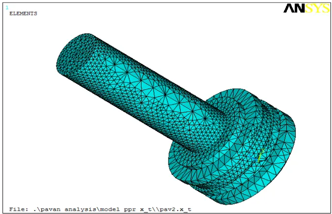
Model generation:
The model is imported from CATIA V5 and the meshing has been carried out using Ansys-mesh tool.
Boundary conditions:
[image:5.612.136.474.445.663.2]A force of 6968N obtained from theoretical calculation is applied on the middle portion of piston rod as shown in Fig 3. The bottom face of the piston rod is constrained to all degrees of freedom.
International Journal of Emerging Technology and Advanced Engineering
Website: www.ijetae.com (ISSN 2250-2459,ISO 9001:2008 Certified Journal, Volume 3, Issue 3, March 2013)
960
[image:6.612.131.476.151.386.2]9.1 Stress distribution of piston rod
Fig 4: Von-mises stress distribution of piston rod
The von mises stress is found to be maximum of 51090Pa. Maximum stress can be seen at area of 60mm
diameter edge portion of the piston rod than at the remaining portion of it as shown in Fig 4.
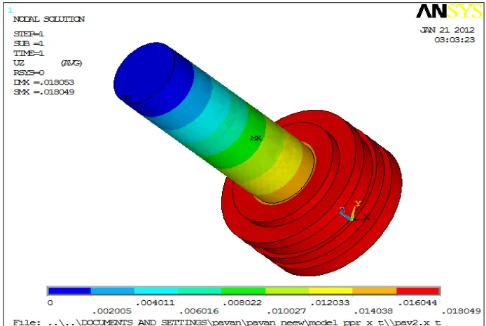
9.2 Static deflection of piston rod
[image:6.612.132.479.456.689.2]International Journal of Emerging Technology and Advanced Engineering
Website: www.ijetae.com (ISSN 2250-2459,ISO 9001:2008 Certified Journal, Volume 3, Issue 3, March 2013)
961
The displacement of piston rod is shown in Fig 5. The maximum static deflection of piston rod is found to 0.0181 x 10-06mm.
X. CONCLUSIONS
1. In the current work, the following conclusion is outlined.
• The fixture for brake spider component machining as per the customer requirements has been attempted successfully, in order to increase the productivity.
2. The static analysis of the important basic component of the designed fixture carried out by finite element method using ANSYS software is summarized as follows.
• Maximum cutting force and maximum clamping force employed for the analysis are 6968N and 20904N respectively.
• Maximum static deflection of piston rod part of the fixture is found to be 0.0181 x 10-06mm and maximum stress (Von mises) is found to be 51090pa. These values are within specified limits which are shown in Fig 4 and Fig5.
REFERENCES
[1 ] S. Ratchev , K. Phuah, S. Liu, “FEA-based methodology for the
prediction of part– fixture behavior and its applications” School of M3, University of Nottingham, United Kingdom, Journal of Material Processing Technology 191 (2001) 260–264
[2 ] Kartik M. Varadarajan, Martin L. Culpepper, “A dual-purpose
positioned-fixture for precision six-axis positioning and precision fixturing” MA02139 (2002), USA
[3 ] Patrick J. Golden, “Development of a dovetail fretting fatigue fixture
for turbine engine materials” Materials and Manufacturing Directorate, Air Force Research Laboratory, Wright-Patterson AFB, OH 45433(2004), USA.
[4 ] Yu Zheng, Chee-Meng Chew, “A geometric approach to automated
fixture layout design”, National University of Singapore, Singapore 117576, Singapore(2005).
[5 ] W. Li, Peigen Li, Y. Rong, “Case-based agile fixture design” School
of MechanicalScience and Engineering,Worcester Polytechnic Institute, Worcester, MA 01609-2280(2005), USA.
[6 ] WassanaiWattanutchariya, “Bonding fixture tolerances for
high-volume metal microlamination based on fin buckling and laminae misalignment behavior”, (2007)
[7 ] F. Mervyn, A. Senthilkumar, S.H. Bok, A.Y.C. Nee, “Development
of an Internet-enabled interactive fixture design system”, 10 Kent Ridge Crescent, Singapore.(2009)
[8 ] K. Nagai, T. Yamaguchi, “Experiments on chaotic vibrations of a
post-buckled beam with an axial elastic constraint”, Gunma 376-8515, Japan.(2010)
[9 ] SadettinOrhan, “Analysis of free and forced vibration of a cracked cantilever beam”, Department of Mechanical Engineering, Faculty of Engineering, Kirikkale University, 71400 Kirikkale, Turkey
[10 ]Rong Y, Bai Y, J Manufacturing Science Engineering, “Automated
generation of fixture configuration design” Trans ASME 1997; 119(2):208–19.
[11 ]Ratchev, K. Phuah , G. Lammel, W. Huang, “An experimental
investigation of fixture–work piece contact behavior for the dynamic simulation of complex fixture–work piece systems”
[12 ]K.C. Aw, W.D.J. Huang, M.W.R.P. De Silva, “Evaluation of