© 2016, IRJET | Impact Factor value: 4.45 | ISO 9001:2008 Certified Journal
| Page 1402
Experimental investigations on structural light weight concrete beams
by blending light weight aggregates
Umesh N G
1, Anilkumar
2Anil Kumar R
31
M.Tech Graduate, Structural Engineering M.S.Ramaiah Institute of Technology Bangalore, India
Phone No. +91 7760479065 Email: [email protected]
2
M.Tech Graduate, Structural Engineering M.S.Ramaiah Institute of Technology Bangalore, India
Phone No. +91 7795284644 Email: [email protected]
3
Assistant Professor, Civil Engineering Dept. M.S.Ramaiah Institute of Technology Bangalore, India.
Phone No. +91 9738217336 Email: [email protected]
---***---Abstract -
The main objective of this study was to comparethe structural performance of NCC and LWC beams of grade M20 and M30. The experimental investigation has been carried out by blending of Cinder and LECA together in place of conventional aggregates for LWC beams. The proportions of Cinder and LECA were 60% and 40% which kept constant for all LWC beams. This proportion was selected based on the literature. The cement was partially replaced by 20% GGBFS in both NCC and LWC beams in order to make concrete durable. A total 12 beams were cast in which six of M20 grade and six of M30 grade for NCC and LWC. The cross section maintained for all the beams were 150mm × 300mm and the length was 2000mm. The experimental study was conducted to know the behavior of these beams under simply supported two point loading and comparison was drawn between beams made out of Normal Conventional Concrete (NCC) and Light weight Concrete (LWC). The results indicated that the light weight concrete beams can be obtained by blending of different light weight aggregates. The ultimate load for LWC beams are more than that of NCC beams of M20 and M30 grades. The deflections for LWC beams were smaller than that of NCC beams of grade M20 where as the ultimate deflections of LWC beams are slightly higher than that of NCC beams of M30 grade concrete.
Key Words: Cinder, LECA, Compressive strength, Light Weight Concrete, Normal Conventional Concrete.
1. INTRODUCTION
This Concrete is the basic important binding material used in the construction field. It is obtained by uniform mixing of cement, sand, aggregates and water along with some pozzolonic materials if required. India is the second largest growing country in terms of population. As population is growing the demands for basic needs of human beings are also increasing. Agriculture is the primary occupation of Indians and nowadays construction has become secondary occupation.
Any structure ultimately transfers the load to the soil strata beneath; the increase in the shear number of structure has increased the stress on mother earth. The
demand for construction space has increased many folds with increase in necessity of human beings. India is having land scarcity, hence vertical growth is preferred than horizontal growth, since more and more people are moving into urban areas lead to lot of land crunch. This land crunch and load increase demands the use of light weight structural concrete. The light weight structural concrete helps in decreasing load as the density is reduced substantially from ranges of 2400 kg/cubic meter to 1800 kg/cubic meter. Lightweight concrete has strength comparable to normal weight concrete, yet is typically 25% to 35% lighter. Structural lightweight concrete offers design flexibility and substantial cost savings by providing: less dead load, improved seismic structural response, longer spans, and etc.
1.1 Beams
Normal concrete is week in tension hence the reinforcement is required to take tensile stresses. Steel is strong in compression as well as in tension. Hence steel is commonly used as reinforcement in the structures. In simple building reinforced structural elements are beams, columns and slabs. Beams are also called as flexural members. These flexural members have sufficient resistance against bending moment and shear force. Beams are one of the major load transferring elements in the RC structures. Beams may be singly reinforced or doubly reinforced. When the depth of the section is restricted, the doubly reinforced section has better strength than that of singly reinforced sections.
2. OBJECTIVES
Based on the literature review conducted, following are the main objectives of the present work
To develop light weight structural concrete by blending with LECA and CINDER for M20 & M30 grade of concrete.
© 2016, IRJET | Impact Factor value: 4.45 | ISO 9001:2008 Certified Journal
| Page 1403
To compare the behaviour of light weight concretebeams and compare with normal conventional beams.
3. MATERIALS AND METHODOLOGY
The materials used in the present investigation are given below;
Cement: In the present investigation ordinary Portland cement of 43 grade confirming to IS8112:1989 with specific gravity 3.15 was used as a binding material.
Fine aggregate: manufactured sand is used as a fine aggregate confirming to Zone II (as per IS 383 – 1970) passing through 4.75 mm IS sieve with specific gravity of 2.53
Coarse aggregate: Locally available granite aggregates passing through 20 mm IS sieve with specific gravity of 2.63. Light weight aggregates: In this study Cinder and LECA were selected as light weight aggregates to replace granite aggregates in the production of LWC.
3.1 LECA:
It is abbreviated as LIGHT EXPANDED CLAY [image:2.595.321.546.259.368.2]AGGREGATES. It is the special type of aggregate which are formed by pyroclastic process in rotary kiln at very high temperature. Since it is exposed to high temperature, the organic compounds burn, as a result the pellets expand and form a honeycombed structure.Whereas the outside surface of each granule melts and is sintered.The resulting ceramic pellets are lightweight, porous and have a high crushing resistance. Fig 1 shows the LECA used in the investigation and Table 1 gives its properties.
Fig -1: LECA
Table -1: Properties of LECA
Sl.
No. Tests Conducted Results
1 Shape Rounded
2 Specific gravity 0.51
3 Bulk Density in Loose state 270 kg/m3
4 Bulk Density in Compacted 285 kg/m3
state
5 Water Absorption 6.5%
3.2 CINDER:
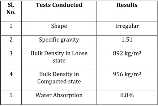
Cinder is a naturally occurring light weight [image:2.595.306.562.415.587.2]rock of igneous origin. It is a pyroclastic material which is similar to that of pumice and has many cavities with low density which can float in water. Cinder is generally black, brown or red in color depending on its chemical composition. Fig 2 shows the cinder used in investigation and Table 2 gives its properties.
Fig -2: Cinder aggregates
Table -2: Properties of Cinder
Sl.
No. Tests Conducted Results
1 Shape Irregular
2 Specific gravity 1.51
3 Bulk Density in Loose
state 892 kg/m
3
4 Bulk Density in
Compacted state 956 kg/m 3
5 Water Absorption 8.8%
© 2016, IRJET | Impact Factor value: 4.45 | ISO 9001:2008 Certified Journal
| Page 1404
Table -3: Mix proportions for M20 grade concrete
1 Cement 306.53 kg/m3
2 GGBFS 76.63 kg/m3
3 Water 191.58 kg/m3
4 Fine aggregate (M. sand) 659.52 kg/m3
5 Coarse aggregates 1118.59 kg/m3
[image:3.595.308.558.296.432.2]6 Water cement ratio 0.50
Table -4: Mix proportions for M30 grade concrete
1 Cement 330.664
kg/m3
2 GGBFS 82.666 kg/m3
3 Water 186 kg/m3
4 Fine aggregate (Manufactured sand) 673.92 kg/m3
5 Coarse aggregates 1095.74 kg/m3
6 Water cement ratio 0.45
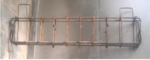
In the experimentation work, for the optimised proportions of Cinder and LECA beams of size 150×300×2000 mm were cast. The total numbers of beams cast and tested were 12, which include 3 for NCC, 3 for LWC of M20 and 3 for NCC, 3 for LWC of M30 grade concrete. The cross section adopted was 150mm X 300mm, for this section of beams 2 numbers of 16 mm steel bars in tension zone and 2 numbers of 10 mm steel bars as anchor bars in compression zone and 8 mm diameter bars @ 200 mm c/c as vertical stirrups were used. The reinforcement was kept constant in all the beams in order to compare each other. The reinforcement details were shown in Fig- 3.
Fig -3: Reinforcement details of Beam
[image:3.595.34.293.297.456.2]The concrete used for the casting of the beams was mixed in the concrete pan mixer. The raw materials required was calculated as per the IS method of mix design. Each mix was fed into the mixer and as the concrete of the first batch was taken out, the next batch of materials was added. This ensured that there was a continuous flow of concrete to cast the beams. The concrete from the mixer was taken on to the water tight platform and it was put into the formwork in three layers and each layer was vibrated by needle vibrator to make sure that the concrete reached all parts of formwork. After the concreting of beam was finished, the top layer of the beam was levelled and given a smooth finish. After 24 hours they are de-moulded. And the curing was done by covering gunny bags as shown in Fig -4.
Fig -4: Curing of Beams
After the curing was completed, the beams were white washed shown in Fig -5 before mounting on the loading frame. All the beams were tested in the loading frame of capacity 1000 kN. All the beams were tested in a simply supported condition. A typical loading arrangement of the beams is shown in Fig -6.
[image:3.595.309.563.546.687.2] [image:3.595.39.283.626.724.2]© 2016, IRJET | Impact Factor value: 4.45 | ISO 9001:2008 Certified Journal
| Page 1405
Fig -6: Loading arrangement
[image:4.595.311.562.609.742.2]The compressive strength of concrete is determined from the cube specimen of size 150mm×150mm×150mm. The cube specimens are casted ass per Indian Standards. The compressive strength of cubes is determined after 28 day curing. The results are shown in Table -5.
Table -5: 28 day Compressive strength of Concrete Cubes
Sl.
No. Concrete Load in kg strength in MPa Compressive
1 M20 NCC #1 79000 34.444 2 M20 NCC #2 76000 33.136 3 M20 NCC #3 77000 33.572 4 M30 NCC #1 96000 41.856 5 M30 NCC #2 98000 42.728 6 M30 NCC #3 96000 41.856 7 M20 LWC #1 70000 30.52 8 M20 LWC #2 68000 29.648 9 M20 LWC #3 69000 30.084 10 M30 LWC #1 80000 34.88 11 M30 LWC #2 82000 35.752 12 M30 LWC #3 83000 36.188
3.3 Load Deformation Behaviour of RC Beams
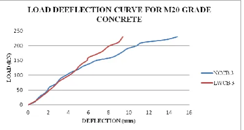
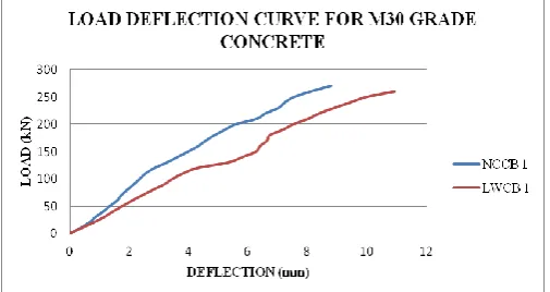
An important aspect in the analysis and design of structures relates to the deformations caused by the loads applied to a structure. Clearly it is important to avoid deformations so large that they may prevent the structure from fulfilling the purpose for which it is intended. But the analysis of deformations may also help us in the determination of stresses. To determine the actual distribution of stresses within a member, it is necessary to analyze the deformations which take place in that member. This project deals with the deformations of simply supported light weight concrete beams and normal conventional concrete beams under two point loading. The combined load-deformation behaviours of beams are shown in below charts.
Chart-1: Load Deflection curve for M20 Grade Concrete
From the Chart-1, it has been observed that, the deflection of the beams increased as the applied load increases. Initially the deflections were same up to 130 kN the deflection of LWC Beam #1 was more than NCC Beam #1. The ultimate loads and deflection were 240kN, 14.6 mm and 230kN, 9.28 mm respectively for NCC Beam #1 and LWC Beam #1.
Chart-2: Load Deflection curve for M20 Grade Concrete
From the Chart-2, it has been observed that, the deflection of the beams increased as the applied load increases. Initially the deflections were same up to 130 kN. Beyond 130kN the deflection of NCC Beam #2 was increasing rapidly with the increase in load than that of LWC Beam #2. The ultimate loads and deflection were 240kN, 14.42 mm and 260kN, 9.10 mm respectively for NCC Beam #2 and LWC Beam #2.
© 2016, IRJET | Impact Factor value: 4.45 | ISO 9001:2008 Certified Journal
| Page 1406
From the Chart-3, it has been observed that, the deflection ofthe beams increased as the applied load increases. Initially the deflections were same up to 120 kN. Beyond 120kN the deflection of NCC Beam #3 was increasing rapidly with the increase in load than that of LWC Beam #3. The ultimate loads and deflection were 230kN, 14.8mm and 230kN, 9.40 mm respectively for NCC Beam #3 and LWC Beam #3.
Chart-4: Load Deflection curve for M30 Grade Concrete
From the Chart-4, it has been observed that, the deflection of the beams increased as the applied load increases. The deflections of the NCC Beam #1 were less than LWC Beam #1 at the same load. The ultimate loads and deflection were 270kN, 8.78mm and 260kN, 10.95 mm respectively for NCC Beam #1 and LWC Beam #1.
Chart-5: Load Deflection curve for M30 Grade Concrete
From the Chart-5, it has been observed that, the deflection of the beams increased as the applied load increases. The deflections of the NCC Beam #2 were less than LWC Beam #2 at the same load. The ultimate loads and deflection were 260kN, 8.97mm and 270kN, 10.35 mm respectively for NCC Beam #2 and LWC Beam #2.
Chart-6: Load Deflection curve for M30 Grade Concrete
From the Chart-6, it has been observed that, the deflection of the beams increased as the applied load increases. The deflections of the NCC Beam #3 were less than LWC Beam #3 at the same load. The ultimate loads and deflection were 280kN, 9.72 mm and 250kN, 9.95 mm respectively for NCC Beam #3 and LWC Beam #3.
Based on Load Deflection curves the following common points were noted,
At the first visual cracking of the beams, the load was considered as the experimental cracking load and the deflection corresponding to this load was noted as deflection at first crack.
It was observed that towards the ultimate load, deflection was increasing rapidly.
[image:5.595.36.289.193.327.2] Beyond a certain stage, deflection continued increasing while there was no increase the load.
© 2016, IRJET | Impact Factor value: 4.45 | ISO 9001:2008 Certified Journal
| Page 1407
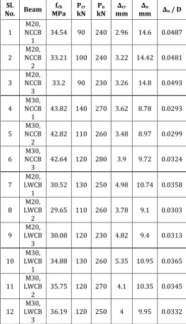
Table -6: Experimental results of tested beams
In Table 6 fck is the compressive strength of the auxiliary cubes, Pcr is the cracking load, Pu is the ultimate load, ∆cr is the deflection at cracking, ∆u is the ultimate deflection and (∆u / D) is the ratio of ultimate deflection to total depth of the section.
The failure modes of beams were shown in following figures,
Fig -7: Crack Pattern of M20 NCC Beam #1
Fig -8: Crack Pattern of M30 NCC Beam #1
Fig -9: Crack Pattern of M20 LWC Beam #1
Fig -10: Crack Pattern of M30 LWC Beam #1
4. CONCLUSIONS
An experimental investigation has been carried out to compare the behavior of light weight concrete beams by blending of light weight aggregates and the normal conventional concrete beams and concluded that,
It is possible to obtain the structural LWC by blending of different light weight aggregates.
For every mix the cubes were cast and an average 28 day compressive strength was 30.084 N/mm2 and 35.61 N/mm2, which were more than the target mean strength for both M20 and M30 LWC respectively.
The ultimate load for LWC beams are more than that of NCC beams of M20 and M30 grades.
The ultimate deflections of M20 grade LWC beams are less than the ultimate deflections of NCC beams of same grade.
The ultimate deflections of M30 grade LWC beams are slightly higher than the ultimate deflections of NCC beams of same grade.
REFERENCES
1. Mr. Anil Kumar R, Dr. P Prakash “Studies on Structural Light Weight Concrete by Blending Light Weight Aggregates” International Journal of Innovative Research in Engineering & Management, Volume-2, Issue-4, July-2015 pp 48-52.
2. R. Kalpana, P. S. Kothai ”Study on Properties of Fibre Reinforced Light Weight Aggregate Concrete” International Journal for Scientific Research & Development Vol. 3, Issue 02, ISSN (online): 2321-0613, 2015 pp 1876 – 1879.
Sl.
No. Beam MPa fck PkN cr kN Pu mm ∆cr mm ∆u ∆u / D
1 NCCB M20,
1 34.54 90 240 2.96 14.6 0.0487
2 NCCB M20,
2 33.21 100 240 3.22 14.42 0.0481
3 NCCB M20,
3 33.2 90 230 3.26 14.8 0.0493
4 NCCB M30,
1 43.82 140 270 3.62 8.78 0.0293
5 NCCB M30,
2 42.82 110 260 3.48 8.97 0.0299
6 NCCB M30,
3 42.64 120 280 3.9 9.72 0.0324
7 LWCB M20,
1 30.52 130 250 4.98 10.74 0.0358
8 LWCB M20,
2 29.65 110 260 3.78 9.1 0.0303
9 LWCB M20,
3 30.08 120 230 4.82 9.4 0.0313
10 LWCB M30,
1 34.88 130 260 5.35 10.95 0.0365
11 LWCB M30,
2 35.75 120 270 4.1 10.35 0.0345
12 LWCB M30,
[image:6.595.30.293.131.588.2]© 2016, IRJET | Impact Factor value: 4.45 | ISO 9001:2008 Certified Journal
| Page 1408
3. Jihad Hamad Mohammed , Ali Jihad Hamad “Aclassification of lightweight concrete: materials, properties and application review” International Journal of Advanced Engineering Applications, Vol.7, Iss.1, 2014 pp.52-57.
4. Dr. V.Bhaskar Desai, Mr. A. Sathyam “Some Studies on Strength Properties of Light Weight Cinder Aggregate Concrete” International Journal of Scientific and Research Publications, ISSN 2250-3153, Volume 4, Issue 2, February 2014.
5. Mohamed R. Afify, Noha M. Soliman “Feasibility of Using Lightweight Artificial Course Aggregates in the Manufacture of R. C. Elements” International Journal of Engineering and Advanced Technology, ISSN: 2249 – 8958, Volume-3, Issue-2, December 2013 pp 290 - 306
6. Dr.Muyasser M. Jomaa'h “Using of Local Limestone as Aggregate in Concrete Mixture” Tikrit Journal of Engineering Sciences, Vol.19, No.1, March 2012 pp 35-43.
7. Payam Shafigh, Mahmoud Hassanpour M, S. Vahid Razavi and Mohsen Kobraei “An investigation of the flexural behaviour of reinforced lightweight concrete beams” International Journal of the Physical Sciences Vol. 6(10), 18 May, 2011 pp. 2414-2421.
8. ACI 211.2-98 “Standard Practice for Selecting Proportions for Structural Light Weight Concrete” 9. ACI 213R-03 “Guide For Structural Light Weight
Aggregate Concrete”
10. IS 8112:2013 “Ordinary Portland Cement, 43 Grade- Specification” Second Revision, Bureau Of Indian Standards, New Delhi, India
11. IS 10262:2009, “Standards Concrete Mix Proportioning Guidelines”, First Revision, Bureau of Indian Standards, New Delhi, India.
12. IS 456:2000, “Plain and Reinforced Concrete-Code of Practice”, Fourth Revision, Bureau of Indian Standards, New Delhi, India