2551
OVERVIEW AND IMPLEMENTATION OF THE TWO MOST
IMPORTANT CANDIDATE 5G WAVEFORMS
ALI JASIM RAMADHAN
Department of Computer Techniques Engineering, Faculty of Technique Engineering, University of AlKafeel, Kufa 31003, Najaf Province, Republic of Iraq
E-mail: [email protected] or [email protected] Orcid Id: 0000-0003-3253-3525
ABSTRACT
Interconnectivity of devices means that 5G is expected to handle high data rates, and even the lowest hierarchy of 5G systems should be flexible. The flexibility of the 5G waveform is important to ensure that different types of traffic can be managed within the same band. In this study, three multicarrier waveforms, namely, the filter bank multicarrier (FBMC), conventional orthogonal frequency division multiplexing (OFDM), and upcoming universal filtered multicarrier (UFMC) waveforms, were analyzed in terms of the probability of error with respect to changes in some operational parameters. These new types of waveforms are ideal for future needs because they solve the problem of time-frequency synchronization. They can support the fragmentation of spectrums because they rely on improved techniques of spectrum localization, which means that they can combine different traffic specifications. The response time is very vital for transmitting very small bursts of information, and 5G simulation tests show a significant benefit regarding the time-frequency efficiency. Because of the cyclic prefix, OFDM and FBMC tend to perform poorly when transmitting short bursts. UFMC performs better than FBMC when transmitting short packets; its performance was better than that of OFDM by 10% in all scenarios. Long sequence tests show that the performance of both FBMC and UFMC are the same.
Keywords:FBMC, OFDM, UFMC, 4G, 5G
1. INTRODUCTION
4G systems utilize orthogonal frequency division multiplexing (OFDM), which is considered to be an appropriate method for improving the spectrum’s efficiency and addressing the frequency selection problem [1]. OFDM is extensively used in multicarrier systems where its symbols are highlighted using a cyclic prefix (CP) and its modulation applies the inverse fast Fourier transform (IFFT). 5G LTE will gain traction in the year 2020 and offer people new services. Such services include wireless broadband data service, which is very crucial in the process of enhancing digital wireless data systems.
After each decade, a new generation system is developed to meet increasing data requirements and new spectral specifications. As such, it is up to the telecommunications industry to focus on future applications so that it can assess areas in which LTE fails to meet the requirements.
Because of the introduction of the 5G standard, other multicarrier systems have gained increasing
attention. The universal filtered multicarrier (UFMC) system is being considered owing to its numerous advantages, especially when the filtering process is carried out on per sub-band criteria. A sinc filter shapes the subcarriers in the frequency domain. Alternatively, the sinc shapes can be eliminated and a more relevant form determined by the filter design can be implemented to achieve a reduction in the side lobe levels [2]. As the interconnectivity of devices is supported by 5G systems, there are definite differences in the characteristics of the nodes being connected to the network (in terms of device capabilities, number of devices, desired response time, size of packets, and frequency of packets), as well as the bursts being transported. As a result of these differences, it is clear that the 5G waveform should provide dedicated services for the various types and needs of the channel with tolerance to mismatches in the time-frequency domain and featuring reduced out of band emissions [3, 4].
2552 area, 10 times higher battery life, 10–100 times increment in data use rates, 10–100 times more interconnected gadgets, and reduction of end-to-end latency by approximately five times [5]. The METIS project aims to achieve these goals by 2020. To achieve these goals, telecoms need to utilize available spectrums better, use spectrums that are above 6 GHz, introduce multiple inputs and outputs, and have small cell generalization. Furthermore, telecoms need to define a new air interface.
4G is based on OFDM modulation, which has two major disadvantages: it lacks waveform flexibility and has bad spectral confinement. These limitations pose a problem when it comes to the multiple services that 5G communication systems will provide in the future. It is necessary to apply dynamic spectrum aggregation to optimize the usage of bandwidths that are lower than 6 GHz [6]. Systems that make use of OFDM tend to have highly granular resource blocks and high emission levels in the out of band (OOB). These problems affect the issuance of low data rate communications by single subcarriers. Further, the Doppler effect is known to cause frequency shifts, especially in high mobility applications. It is very difficult to obtain a substantial reduction in latency in OFDM in addition to the spectral efficiency drops that occur when cyclic prefixes are used to curb interference. Therefore, it is necessary to develop a new system with a flexible waveform.
In this study, different waveforms, such as filter bank multicarrier (FBMC), UFMC, and OFDM, were investigated and compared based on the probability of error with respect to several parameters, which will be introduced in subsequent sections of this paper. The remainder of this paper is organized as follows. Section II of the paper presents the three investigated waveforms, namely UFMC, FBMC, and OFDM, while Section III introduces block illustrations of the three waveforms. In Section IV, a comparison of the metrics is presented, while Section V focuses on the system performance obtained from trace driven simulations. The conclusions of the study are presented in Section VI, as well as suggestions and recommendations.
2. THEORETICAL OVERVIEW
OFDM is the reference for multi-carrier modulation. Two variants with a lesser degree of
maturity are presented, namely FBMC and filtered multi-tone. Recently, FOFDM has emerged from discussions on 5G systems. FOFDM links sub-band filtering instead of assessing subcarrier by subcarrier. In this section, various waveforms and the OFDM outline are introduced. The following parameters were used.
K: Value of sub-symbols in the case of block transmission
c: Symbol sent over each carrier in complex constellation
Ts: Sampling duration, which is considered unity in this study
a: Symbol sent over to each carrier in real valued constellation
T: Duration of each single of the OFDM symbol M: Maximum number of subcarriers = Size of the IFFT
2.1 Orthogonal Frequency Division Multiplexing
OFDM is often considered to be advantageous because it makes use of subcarriers that overlap to create parallel and modulated data streams. Such approach is beneficial as it enhances bandwidth efficiency compared to other approaches. The orthogonal approach is used to prevent inter-carrier interference. Flat fading can be achieved in the OFDM system by modulating low-rate data stream on subcarriers that are derived by the fast Fourier transform. For a single carrier modulation, transmitted information makes use of an entire bandwidth while the OFDM data is modulated in a number of limited subcarriers. These subcarriers have a lower bandwidth than the bandwidth of the channel, which results in each subcarrier having a flat fading channel. A cyclic prefix is introduced after all the symbols, with Lcp being the length. Introducing the prefix enhances the robustness of a channel against frequency selectivity by improving its flatness at each subcarrier. Transmission in OFDM occurs in a symbol by symbol (K=1) manner. Thus, OFDM has a baseband symbol that can be denoted as k∈[−Lcp, M−1],
(1)
In the above equation, cm is the transmitted
2553 Subsequently, simple approaches of equalization and channel estimation are used to retrieve the orthogonality at the receiver side. Nonetheless, OFDM makes use of a rectangular pulse, which is disadvantageous in some cases. Hence, shaping the pulse will be tacitly achieved using the Fourier transform.
2.2 Filter Bank Multi-Carrier (FBMC)
FBMC introduces structured transmission, which permits the avoidance of the Balian–Low theorem requirements [8]. FBMC manages to sustain transmission at the Nyquist rate and orthogonality by using better pulse shapes. Subcarriers are used to transmit complex symbols in OFDM. On the other hand, the imaginary and real components of complex symbols are transmitted in the structured technique, and they have a symbol duration delay of T/2. FBMC’s baseband signal can be described (where k is an integer) as given below [10].
(2) (2) (2)
where g is the filter, N1 (= M/2) represents the offset of the discreet time. φm,n is considered an extra phase term symbol index n and m
(subcarrier), which can be written as π/2(n+m).
am,n is the true value of the symbols that have
been transmitted and can be obtained from the imaginary and real sections of the QAM constellation. g must meet the standards of the orthogonality condition for perfect reconstruction.
(3)
where ∗ is the complex conjugation, δm,p = 1 if m =
p, and δm,p = 0 if m ≠ p.
FBMC makes use of FFT/IFFT algorithms. Nonetheless, compared to OFDM, it exhibits complexity issues. Complexity arises from the use of half-duration real symbols. The use of such symbols implies that the FFT/IFFT has to perform at a rate that is twice as fast. Furthermore, complexity occurs because of additional filter blocks
2.3 Universal Filtered Multi-Carrier
In UFMC, all the available bandwidth is divided into B sub-bands. Classical OFDM modulation is used on each sub-band [11]. On each sub-band, modulated signal and FIR filtering are applied with a length L. The UFMC signal is obtained as a summary of B filtered modulated sub-band signals. For each block with a length denoted as L+M-1, the UFMC signal can be given as k∈[0, M+L−1].
(4)
where cim denotes the complex-valued symbols for
subcarrier m and sub-band i. The definition of a sub-band under the UFMC systems is placed as a single physical resource block. As all subsequent blocks do not overlap, orthogonality is guaranteed. The traits of the filters being used are the ones that determine orthogonality in the frequency. Furthermore, the transition interval that occurs between subsequent blocks as a result of filtering acts as a guard interval and shields the transmitted symbols for as long as L is more than or equal to the highest delay spread due to a multipath channel. However, a recent study [12] proposed a realization scheme that performed better than the one obtained from a direct implementation that makes use of the above formula. However, an extra cost is incurred compared to the OFDM references, which increases by a minimum of a factor of two for uplink (based on the assumption that a minimum number of resource blocks are in use) and a factor of between eight and ten for downlinks.
3. SYSTEMS DESCRIPTION
3.1 OFDM
2554 formation. The data can then be described as OFDM and is ready to be transmitted. A digital/analog converter (DAC) is used to convert the data from digital to time-domain analog data. The signal is up-converted using RF modulation to achieve the transmission frequency. When the data is sent via the antenna, OFDM signals pass through all the wireless channel impairments.
At the receiving end, signals will be down-converted and changed back to a digital form through an analog/digital converter. It is important to monitor the frequency offset because of mobility and the channel. Down-conversion operations should be implemented during carrier frequency recovery. After digitization is complete, symbol timing synchronization is performed. The OFDM signal can then be demodulated using the FFT operator. Then, channel estimation is performed through the demodulated pilots. These estimations allow for complex data that have been received to be de-mapped using the diagram of the transmission constellation. The originally transmitted stream of bits is recovered using FEC de-interleaving and decoding. The most commonly known and used multicarrier format is the CP-OFDM of the IEEE 802.11 and 3GPP LTE.
3.2 FBMC
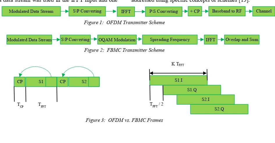
The block diagram shown in figure 1 can be used to implement the filter bank. It is adequate to spread the FFT and IFFT. In the previous section, a data stream was used in the IFFT input and one
carrier was modulated. In a filter bank with overlapping factor K, a stream of data modulates 2K-1 carriers as illustrated in figure 2. Hence, the filter banks in transmitters can be used with extended IFFT of magnitude LM to obtain all the required carriers. Each data segment is multiplied by the coefficient of the filter frequency, then transmitted to the 2K-1 input of the IFFT as follows: (i−1)K+1 to (i +1)K−1. Thus, the elements of data are spread over different IFFT inputs as illustrated in figure 2. For each cluster of input data, the IFFT output is a group of KM
samples. 1/M denotes the symbol rate, K is the number of subsequent outputs that overlap each other in the time domain. Thus, the output of the filter bank is as shown in figure 3.
[image:4.612.92.565.468.714.2]The implementation of the receiver is founded on the FFT (extended) of the magnitude KM. In such a scenario, the FFT input blocks overlap. In the FFT output segment, the elements of data are collected using a weighted de-spreading operation. The frequency coefficients of the Nyquist filter determine data recovery. When the receiver and transmitter are connected, the entire system’s delay is denoted as KM samples. An important advantage of this scheme is its simplicity, as shown in figure 2. The key difference is the complexity that arises when FFT is increased in size from M to KM. The overlapping of the time domains of the FFT inputs and the IFFT outputs creates significant redundancy that can be addressed using specific concepts or schemes [13].
Figure 1: OFDM Transmitter Scheme
Figure 2: FBMC Transmitter Scheme
Figure 3: OFDM vs. FBMC Frames
Modulated Data Stream S\P Converting IFFT P\S Converting + CP Baseband to RF Channel
Modulated Data Stream S\P Converting OQAM Modulation Spreading Frequency IFFT Overlap and Sum
S1.I
S1.Q
S2.I
S2.Q K TFFT
TFFT / 2
CP S1 CP S2
2555
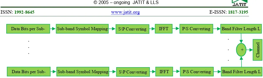
Figure 4: UFMC Transmitter Scheme
3.3 UFMC
Filtering in UFMC is carried out on subsets of the complete band and not the entire or single subcarriers. Figure 4 shows a UFMC transmitter using a single antenna with B sub-bands. The ith UFMC submodule (i ϵ {1,2,..., B}) makes the (N+Nfilter−1)-dimensional time-domain with a baseband vector of xi, while using the design parameters of UFMC for each sub-band bearing the complex QAM symbol vector si. Dimensions are rated as ni × 1. N is the needed number of samples for each symbol to denote all sub-bands without having to bring in aliasing. It is dependent on the covered bandwidth. Each sub-band’s sample rate have to be aligned with the others. The length of the filter is given as Nfilter.
Multicarrier symbols are considered while the temporal symbol index is dropped to make notation easy. Single sub-band signals are then combined to generate the transmit vector x. With regards to uplink, individual sub-modules take up the frequency portion that a particular user has been given. On the other hand, for downlink, individual sub-modules take up the entire frequency band that is available to transmit data to multiple users. The IDFT spreader is used to convert the ni complex QAM symbols to the
time-domain before a sub-band filter is applied. The UFMC transmitter’s spectral settings influence the choice of B, which has to handle system design targets. If the system is used in a fragmented spectrum, B can be selected using the number of spectral bands available for use. It may vary in some cases especially when other wireless services have populated the spectral sub-bands [13].
4. COMPARISON OF PARAMETERS
This section presents an analysis of different waveforms. Several metrics were used for the comparison, including mobility, spectrum
confinement, latency, compatibility with 4G LTE, complexity, spectral efficiency, and tail issue. This type of comparison is necessary because it gives a holistic perspective of the pros and cons of various schemes already presented.
4.1 Spectral Efficiency
OFDM is not able to attain maximum efficiency because CP has been added to the length of the TCP. As a result, there are inefficiencies associated with the process:
(5)
On the other hand, the FBMC scheme follows the Nyquist rate and does not make use of Cp. As such, achieving maximum efficiency is possible:
(6)
F is the spacing between various subcarriers. Maximum efficiency for an orthogonal system is highest when T.F = 1. Lastly, no CP is required in UFMC. However, after the OFDM modulation, zero padding is employed to form an isolation between the subsequent symbols that come after FIR time domain filtering. The value of the padded zeros is equal to the length of the FIR filter minus one [13]. This implies that the overall spectral efficiency is equal to that of OFDM:
(7)
The padding duration is given by TZP and is the
same as OFDM’s TCP.
4.2 Time–Frequency Efficiency
ηtf denotes the time frequency efficiency defined as ηtf = ηf.ηt.
Data Bits per Sub- Sub-band Symbol Mapping IFFT Band Filter Length L
Channel
S\P Converting P\S Converting
+
Data Bits per Sub- Sub-band Symbol Mapping S\P Converting IFFT P\S Converting Band Filter Length L
. . .
.
.
2556 ηt is the time direction’s efficiency with regards to the information conveying body of the burst in relation to the total length, including the tails.
ηf refers to the efficiency in the direction of the frequency with regards to the number of usable subcarriers versus the total number of subcarriers that are available in a particular band. The findings illustrated using information given above clearly show that UFMC has better performance (approximately 10%) than OFDM. Moreover, there are additional benefits such as improving spectral properties and resilience against time and frequency misalignments. FBMC has demonstrated efficiency for long bursts. Nonetheless, the efficiency of time frequency decreases significantly when using small bursts [13]. Thus, UFMC is the most preferred choice when designing a system that has to factor in short burst transmission in the overall operational parameters.
4.3 Tail Issue
During burst transmissions, the tail issue indicates likely overlapping between two separate bursts. This implies that in the time domain, the symbols are not entirely isolated. Instead, some sections of the symbols overlay each other. This problem was observed in the FBMC scheme. Regarding the OFDM scheme, all the symbols are isolated from each other in the time domain [13]. Thus, tail issues do not occur. UFMC is used to set the filter length and it applies zero padding to contain the filtering tails. UFMC has almost the same traits as those of OFDM in this regard: each symbol in UFMC is totally separated in the time domain, so that tail issues do not occur.
4.4 Spectrum Confinement
There are two main issues with CP-OFDM that ultimately affect the quality of spectrum confinement, namely spectral leakage due to waveform discontinuity and the rectangular shape of the OFDM pulse. The problem of waveform discontinuity can be solved when the symbol edge’s envelop smoothly reduces to zero [13]. The second problem due to the shape of the OFDM waveform can be rectified using a prototype filter in place of the rectangular filter. The length of the prototype filter is greater than the FFT size and it has good frequency localization. The discontinuity issue plaguing UFMC can be solved by FIR filtering. Nonetheless, improvements in the
spectrum confinement are not as significant as those of FBMC.
4.5 Mobility
The robustness of mobility is very important in 5G networks. In general, FBMC schemes are considered to be robust against the Doppler Effect because they employ the subcarrier filtering process. Comparatively, the UFMC scheme manages the Doppler Effect in a way that is similar to that of OFDM [13]. The benefit is that the spacing of subcarriers can be increased for a select sub-brand if there is a need to serve high mobility clients.
4.6 Latency
Latency should be considered in 5G networks. OFDM is preferred in this regard because it has a short transceiver latency that comes from the CP (for instance, T+TCP) and the FFT transform. Increasing the filtering will increase the latency [13]. In addition, spectrum confinement and latency are competing factors. The FBMC scheme has the highest latency, while UFMC swaps CP with the filtering transition period. Ultimately, UFMC has a similar latency as OFDM.
4.7 Complexity
OFDM has the benefit of having a low level of modern complexity. When working with some new types of advanced modulation systems, one has to contend with a reduced level of simplicity. The new technologies should be compared with OFDM. The FBMC scheme’s complexity is more than double [13]. In terms of UFMC, direct implementation will result in a substantial rise in the degree of complexity. The rise in complexity is as a result of the modulation block that utilizes one FFT transform.
In an LTE setup where 100 resource blocks are designed to be modulated, the extra intricacy will increase by a factor in the hundreds. Here, the modulation complexity can be reduced by up to a factor of 30 using frequency domain realization. Compared to OFDM modulation, the overall modulation complexity increased by a factor of 8 to 10 for base station side downlink. Complexity in the demodulation segment increased by more than a factor of 2 compared to the demodulation that occurs in OFDM.
4.8 Compatibility with 4G
2557 Instead, it means that the new 5G system should make use of the existing LTE techniques such as MIMO coding and reference signal design. Backward compatibility should be possible in a straightforward manner. Nonetheless, FBMC systems can only transmit real value symbols due to the offset QAM signal type [13]. Thus, a new system cannot be expected to utilize LTE approaches. The UFMC scheme has the same qualities as those found in signals generated by OFDM. Thus, compatibility with LTE will be easy.
5. RESULTS AND DISCUSSION
In this section, the UFMC and FBMC waveforms are presented and compared with those of OFDM. The results were generated using MATLAB software. In the evaluation process, three performance metrics are used, namely the peak to average power ratio, probability of error, and the power spectral density. Prior to the simulations, it can be predicted that some gain will be made in the last two metrics. Nonetheless, regarding the PAPR standard, OFDM is preferred because of filtering observed in both UFMC and FBMC, which enhances the PAPR of FBMC to become slightly inferior to that of OFDM.
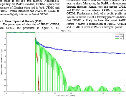
5.1 Power Spectral Density (PSD)
The power spectral densities of FBMC, OFDM, and UFMC are presented in figure 5. dB
represents the PSD, which is a function of the normalized frequency. In this case, it is evident that in FBMC, the power in the OOB is significantly low compared to the equivalent band. Hence, it is safe to assume that in terms of PSD, FBMC ranks better than UFMC and CP-OFDM.
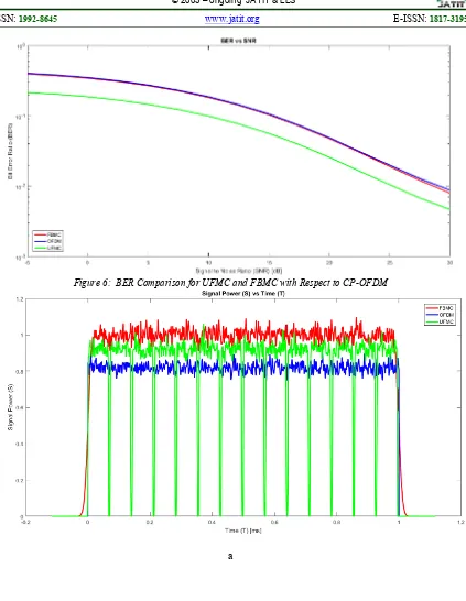
5.2 Bit Error Rate (BER)
The probability of error is presented as the BER of FBMC, UFMC, and OFDM as shown in figure 6. The figure shows that an increase in the BER results in increase in the modulation level, which is consistent with theoretical expectations.
The simulations indicate that the FBMC and OFDM waveforms are similar with regards to BER. Hence, UFMC has the best overall BER.
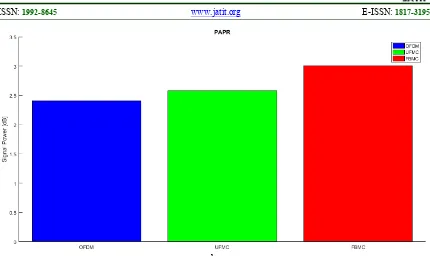
5.3 Peak-to-Average Power Ratio (PAPR)
In theory, CP is appealing for power amplifiers because it has a constant amplitude, which reduces the PAPR. In addition, CP allows for better coexistence with OFDM and slightly smaller FFT receive sizes. Moreover, the PAPR is deteriorated through filtering. Hence, one can expect UFMC and FBMC to have inferior PAPRs compared to OFDM. Furthermore, lack of a cyclic prefix on symbols and the use of a filtering process indicate that FBMC is likely to have the worst PAPR. Figure 7 shows a comparison of FBMC, OFDM, and UFMC in terms of PAPR and signal power.
[image:7.612.92.520.350.679.2]2558
Figure 6: BER Comparison for UFMC and FBMC with Respect to CP-OFDM
2559 b
Figure 7: Comparison of OFDM, UFMC, and FBMC in Terms of: a) Signal Power, b) PAPR
6. CONCLUSIONS
This study investigated the implementation of two different potential variants of 5G, namely FBMC and UFMC. The performance of the two schemes were compared to that of OFDM. Simulation results show that the waveform’s performance varies based on some operational parameters. Hence, when selecting the waveform of the next generation network, factors such as complexity, latency, and tail issue should be considered. UFMC and FBMC improved the PSD but performed poorly in terms of the PAPR, although the PAPR obtained using UFMC was mostly similar to that obtained using OFDM. UFMC enhanced the BER; based on other metrics, UFMC is considered to be the best 5G system candidate.
REFERENCES
[1] A.J. Ramadhan, “Implementation of 5G FBMC PHYDYAS Prototype Filter,”
International Journal of Applied Engineering
Research, Vol. 12, 2017, pp. 13476-13481.
[2] A.J. Ramadhan, “5G Network Goals: A
Comparative Investigation of the Spectral Efficiency and Other Performance Parameters of 4G OFDM and 5G GFDM Signals,” Journal of Engineering and Applied Sciences, Accepted, 2019.
[3] A.J. Ramadhan, “Implementation of a 5G
Candidate Filtered-OFDM Waveform,” International Journal of Engineering Research and Technology, Accepted, 2019.
[4] P. Banelli, S. Buzzi, G. Colavolpe, A. Modenini, F. Rusek, and A. Ugolini, “Modulation Formats and Waveforms for 5G Networks: Who Will be the Heir of OFDM? An Overview of Alternative Modulation Schemes for Improved Spectral Efficiency,”
IEEE Signal Processing Magazing, Vol. 31,
2014, pp. 80-93.
[5] Metis Project, Metis deliverable D1.1: Scenarios, requirements and KPIs for 5G mobile and wireless systems, 2013.
[6] H. Bogucka, P. Kryszkiewicz, T. Jiang, and A. Kliks, “Dynamic Spectrum Aggregation for Future 5G Communications,” IEEE
Communications Magazine, Vol. 53, 2015,
pp. 35-43.
[7] G. Wunder, P. Jung, M. Kasparick, T. Wild, F. Schaich, Y. Chen, S. Ten Brink, I. Gaspar, N. Michailow, A. Festag, and L. L. Mendes, “5GNOW: Non-orthogonal, Asynchronous Waveforms for Future Mobile Applications,”
IEEE Communications Magazine, Vol. 52,
2014, pp. 97-105.
[8] H. Feichtinger and T. Strohmer, “Gabor Analysis and Algorithm – Theory and Applications,” Birkhäuser, 1998.
2560 Multiplex,” Proceedings of the IEEE, Vol. 83, 1985, pp. 982-996.
[10] A.J. Ramadhan, “A Novel MIMO-OFDM Technique for Improving Wireless Communications System Performance Based on SF–BC,” International Journal of
Computer Applications, Vol. 131, No. 1,
2015, pp. 28-31. DOI:
10.5120/ijca2015907225.
[11] V. Vakilian, T. Wild, F. Schaich, S. ten Brink, and J.F. Frigon, “Universal-filtered Multicarrier Technique for Wireless Systems Beyond LTE,” Proc. IEEE Globecom 2013
Workshop.
[12] T. Wild and F. Schaich, “A Reduced Complexity Transmitter for UF-OFDM,”
Proc. VTC, Spring 2015.
[13] A. Geth, “Universal-filtered Multi-carrier,”