5035
GRAPH BASED SIMPLIFIED CRACK MODELING
IN BATIK PATTERN GENERATION
PURBA DARU KUSUMA
School of Electrical Engineering, Telkom University, Bandung, Indonesia E-mail: [email protected]
ABSTRACT
Crack pattern is very rare in traditional or classic batik pattern. So, it is very challenging to explore crack pattern as batik pattern. Unfortunately, existing crack model or crack propagation model is very complex so that it is very resource consuming because crack modeling usually is used in mechanical engineering which is needed exact calculation. In the other hand, in computer based batik pattern generation, algorithm must be simple so that batik pattern can be generated fast. Exact calculation is not necessary in batik pattern generation. In this research, we propose simplified crack modeling and it is implemented in batik pattern generation. This proposed model is developed based on graph model. The proposed model adopts crack characteristics, such as: initial stress, energy reduction, and material resistance or toughness. Crack propagates randomly in certain direction. This model has been successfully implemented in generating batik pattern. Improvisations occur both in batik object pattern and background image. Based on the test, crack split probability has positive linear relation with number of crack segments and number of split activities. Ratio between initial energy and energy reduction has positive linear relation with the number of crack segments.
Keywords: Crack, Graph, Batik, Traditional Pattern.
1. INTRODUCTION
Batik is one of famous traditional heritage in Indonesia. Many patterns can be found in Batik. Nowadays, batik pattern can be generated in two ways. First, the pattern is generated manually. Second, the pattern is generated by using computational method. By using computational method, the pattern can be generated faster so that it can reduce the production cost and time. Most of patterns are based on natural objects, such as plants or animals. Both are living objects. In the previous work, we has proposed fibrous root model in creating batik pattern [1].
Many patterns are not based on living objects but natural phenomenon. The example is Danliris pattern. This pattern illustrates rainfall. This pattern is very popular. Danliris pattern is usually used in wedding party. This pattern symbolizes good wealth, especially for the couple. The other batik pattern is Megamendung. Megamendung is batik pattern that illustrates cloud. This pattern is famous traditional Cirebon city batik pattern. The pattern is similar to Chinese traditional cloud object. It is because there is culture acculturation between Chinese, Islam, and Javanese
cultures for long centuries. Unfortunately, natural or social phenomenon [2] based pattern is very rare compared with living object pattern. So, exploring natural phenomenon and then using it to create batik pattern is very challenging.
One of the natural phenomena is crack. ]. Crack is a natural phenomenon and easily to be found. Crack modeling has been studied widely in mechanical engineering [3-13]. It happens in many material surfaces, such as building wall, mirror, glass, ceramic, etc. For some aspects, such as safety, crack is a problem. In the other hand, the crack pattern has artistic value.
5036 was proposed in crack model research in computer graphic field. Unfortunately, the calculation in the existing crack models in computer graphic field is not simple enough [14-19]. The other work is improvisation. The basic object can be improvised to increase the variation. It is because batik is an art work. As far as it is beautiful and has art value, improvisation or modification is acceptable. So, the existing crack model must be simplified so that it can be used to generate batik pattern.
The research question in this paper is how to simplify the existing crack model so that it can be implemented to generate batik pattern faster and easily improvised. The more specific question is how graph based approach can be used to simplify and to modify the existing crack modeling.
In this research, we propose simplified crack model so that the calculation is not complex. The proposed model is developed based on graph theory. The crack still can be recognized even the calculation is simpler. The crack model then is used to create batik pattern.
This paper is organized as follows. In the first section, we explain the background, motivation, and the purpose of this research. In the second section, we describe the literature review about the existing crack model. In the third section, we explain the proposed model. In the fourth section, we explain the implementation and modification of the model so that it creates batik pattern. In the fifth section, we explain the testing and the result analyzes of the model. In the sixth section, we make conclusion of the work and explain the future research potentials.
2. EXISTING CRACK MODEL
Crack is one of natural phenomena. Crack can be caused by aging process or weather aspect [18]. In all materials, aging is a natural process. Aging process can cause damage [18]. This damage can be caused by external factors such as air condition, mechanical aspect, or organic material growth [18]. Damage also can be caused by internal factors such as defect that may occur during manufacturing process [18]. Basically, crack occurs because of contraction in the material surface [18].
There are two types of crack. They are brittle material fracture and ductile material fracture [18]. The crack propagation in those materials is different. In ductile material, crack grows slowly with many plastic deformations [18]. In brittle
[image:2.612.314.521.252.704.2]materials, crack grows fast with few plastic deformations [18]. Because of the material characteristic, some researches in crack modeling used specific material as their study case, such as: ductile-brittle transition region [3], cement materials [4], alloy [7], ductile material [17], carbon steel [8], and stiff material [19]. In some research, specific material functions are also used as study case, such as: amplitude loading [5], horizontal wells [6], reservoir [9], fatigue loading [16], and cyclic axial-torsion loading [12]. Other research developed general crack model for all materials [18,19].
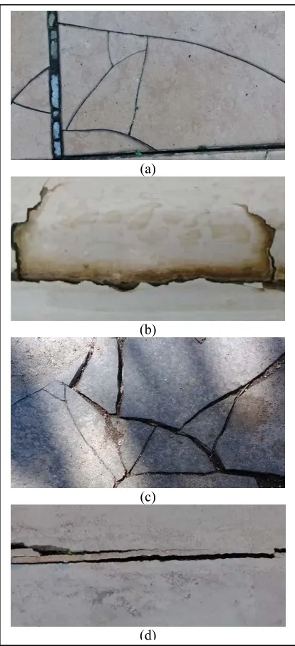
Figure 1: Crack in Material Surface
(a)
(b)
(c)
5037 Different crack propagation can occur in different materials. The illustration of crack in different material can be seen in Figure 1. In Figure 1a, crack occurs in ceramic tile floor. This crack pattern can also be found in glass crack. This crack pattern is similar with crack in Figure 1c. In Figure 1c, crack occurs in mortar based carport floor. These cracks are examples of crack that occurs in brittle material. In Figure 1d, crack occurs in wood door. There are fewer crack splits in this crack. In Figure 1b, crack occurs in fiber based bath pool. This crack is example of crack that occurs in ductile material.
In mechanical engineering, crack modeling uses complex formulae and calculations. It is because the objective is to calculate or to predict crack growth or propagation precisely. Parameters that are common in crack modeling in mechanical engineering is fracture toughness, initial stress, critical stress, crack length, process zone, and crack arrest [3]. Crack can be divided into phases: fracture initiation, local instability, stable tearing, and steady state [3].
In computer graphics, crack modeling can be divided into two groups. The first group is physical model. The second group is non-physical model. Some popular methods in physical model are mass spring model, finite element method [5,15,16], and mesh free method [18]. Mass spring method uses discrete approach and graph representation [18]. In finite element methods, material can be represented as a set or collection of disjoint element [18]. Some methods in non-physical model are image-based method and procedural method [18]. Some studies visualized two dimensions simulation [6,9] and the others visualized three dimensions simulation [16,17]. Linear elastic fracture mechanics can be used to simulate two dimensions modeling and non linear fracture mechanics can be used to simulate three dimensions crack modeling [4].
3. PROPOSED MODEL
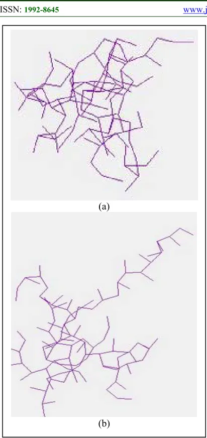
[image:3.612.312.524.103.250.2]In this research, we proposed crack modeling based on graph model. By using graph, crack model can be represented as set of nodes and lines. Line is connector between nodes. The line direction represents crack propagation. Line length represents the crack length in a segment. The destination node represents the end of a crack segment. When it propagates, crack can split into more than one direction. It is a branching process. This crack is illustrated in Figure 2.
Figure 2: Crack Model
The explanation of Figure 2 is as follows. At the beginning, crack is initiated at node 1. Crack then propagates to node 2, 3, 4, 5, and 6 consecutively. There is crack split at node 3 and node 4. At node 3, new crack propagates to node 7 and node 8. At node 4, crack propagates to node 9 and node 10. The link characteristic is single direction. If the crack propagates from node 2 to node 3 then the crack will not propagate from node 3 to node 2.
The proposed model is developed based on some assumptions. First, crack may propagate in any direction. Second, when the crack splits, the parent node produces only two child nodes. Third, the crack deviation and crack segment length is generated randomly and follows uniform distribution. Fourth, the energy or stress is reduced during crack propagation. Five, the crack propagation stops when the energy that is contained in it is lower than the material resistance.
At the beginning process, some variables are initiated. Variable c is set of nodes with c0 is the
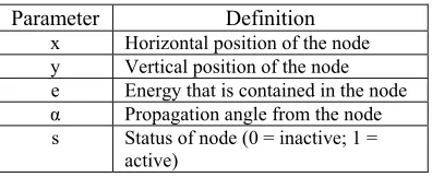
[image:3.612.320.518.611.692.2]initial crack. Variable n is the number of nodes in the crack model. Variable c has some parameters {x,y,e,α,s}. The explanation of the parameters is described in Table 1.
Table 1. Crack Node Parameters
Parameter Definition
x Horizontal position of the node y Vertical position of the node e Energy that is contained in the node α Propagation angle from the node s Status of node (0 = inactive; 1 =
active)
5038 mres indicates the material crack resistance.
Variable emin and emax is the range of energy
reduction factor during crack propagation. The value of emin and emax ranges from 0 to 1. Variable
pslit is the probability that the crack will split.
Variables lmin and lmax define the minimum and
[image:4.612.92.300.209.369.2]maximum value of crack length for every crack segment. The main process algorithm is described in Figure 3. Based on Figure 3, it can be seen that crack model still runs as far as there is active node.
Figure 3:Main Process Algorithm
The process() procedure is a procedure that executes crack process. In this procedure, all nodes are checked. If the node is active and the energy inside the node is higher than the material crack resistance, the crack will propagate from this node. Else, the node status will inactive. This algorithm is described in Figure 4.
[image:4.612.312.508.439.543.2]
Figure 4: process() Procedure Algorithm
There are two possible actions during crack propagation. The first action is new crack segment will be created. It means one new node will be created. The second action is crack split occurs. It means that there are two new nodes will
be created from this node. This situation is situational and stochastic. It is depended on the probabilistic to split (psplit) and current probabilistic
to split (pc_split). The current probabilistic to split
value is set while the node propagates. The pc_split
value is determined randomly and follows uniform distribution. The propagate procedure algorithm is described in Figure 5.
Figure 5:propagate() Procedure Algorithm
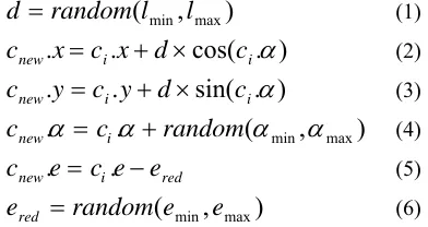
In the extend() procedure, parameters in new node (cnew) are set. These parameters are all
node parameters. The formulae are described in Equation 1 to Equation 6. In equation 4, there are αmin and αmax which are the minimum and
maximum angle. In equation 5, there are emin and
emax which are the minimum and maximum energy
reduction. After new node is created, the old node status will be set inactive.
)
,
(
l
minl
maxrandom
d
(1))
.
cos(
.
.
i i
new
x
c
x
d
c
c
(2))
.
sin(
.
.
i i
new
y
c
y
d
c
c
(3))
,
(
.
.
c
random
min
maxc
new
i
(4)red i
new
e
c
e
e
c
.
.
(5))
,
(
e
mine
maxrandom
e
red
(6)After new node is created, a new link will be created to connect the old node with the new node. After new link is created, the number of link is incremented. The parameters in the link is described as a set {sx,sy,ex,ey}.
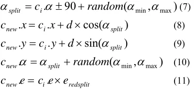
In split procedure, two new nodes are created. Parameters in the first node follows rule in equation 1 to equation 4 except the energy reduction. The second node is the split node. This new node can be of the right or on the left of the old node. It is probabilistic with equal opportunity. The split angle variable is symbolized in αsplit. The split
angle value is determined by equation 7. Then, the
Begin
n_node ← n
For i=0;i<$n_node;i++ Begin
If ci.s = 1 then
Begin
If ci.e > mres then
propagate() else
ci.s ← 0
End End End Begin
run ← “on” while run = “on” Begin
process() livenode ← 0
for i=0;i<n;i++ begin
if ci.s = 1 then
livenode++ end
if livenode = 0 then run ← “off”
End End
Begin
pc_split ← random(0,100)
if pc_split > psplit then
[image:4.612.90.301.488.643.2]5039 other parameters follow rule in equation 8 to equation 11.
)
,
(
90
.
min
max
split
c
i
random
(7))
cos(
.
.
i splitnew
x
c
x
d
c
(8))
sin(
.
.
i splitnew
y
c
y
d
c
(9))
,
(
.
random
min
maxc
new
split
(10)redsplit i
new
e
c
e
e
c
.
.
(11)4. IMPLEMENTATION
[image:5.612.91.291.130.237.2]The proposed crack model then is implemented into batik pattern generation application. The application is a web based application and is coded in PHP language. By this application, the crack model is used to generate an image with the size is 2000 x 2000 pixels. The basic result image is shown in Figure 6.
Figure 6: Basic Image Result
This basic image result then can be manipulated and be improvised to create batik pattern image. In this research, we propose some batik pattern variations based on this basic image. The modification can be in the crack pattern, in the background image, or both.
The first modification is in the crack pattern. Basically, the crack pattern contains set of nodes and links. Batik pattern can be implemented at the nodes, links, or both. Modification is illustrated in Figure 7.
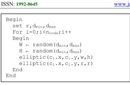
[image:5.612.318.518.231.633.2]In Figure 7a, the modification is in the set of nodes. The object of the nodes is small elliptic with a circle inside it. The elliptic object has randomized size. The circle object has fix size. Meanwhile, the link object is still a simple line. The algorithm of this modification is described in Figure 8. In Figure 8, elliptic function is a function to create elliptic object. Parameters inside the function are horizontal coordinate, vertical coordinate, width, and height.
Figure 7: First Modification Result
(a)
(b)
[image:5.612.94.296.340.562.2]5040
Figure 8: First Modification Algorithm
In Figure 7b and Figure 7c, the modification occurs in both nodes and links. The objects of the nodes and links are set of circles. In the node object, the circles are around the coordinate of the nodes. In the link object, there is array of circles from the starting point to the end point of the link. The algorithm of this modification is described in Figure 9. In Figure 9, there are new variables, they are nnl, nnd, r1, rn, and rd. Variables n-nd and nnd are the number of link circles and the
number of node circles. Variables rl, rn, and d are
[image:6.612.317.526.173.265.2]the radius of the links circle, the radius of the nodes circle, and the distance between the node position to the circle surrounding it.
Figure 9: Second Modification Algorithm
[image:6.612.319.516.391.708.2]In Figure 7c, the third modification is by placing flower like object at the node position beside the second modification. This is done by placing four elliptic object at the top, left, bottom, and right of the node. Then, a circle is put on the node position. The algorithm of this is described in Figure 10. In this algorithm, new variables are used to set the size and distance of the flower like object. Variables sl and ss are used to set the dimension of
the elliptic objects around the center of the node. The value of the sl is bigger than the ss. Variable d
is used to set the distance between center of the node and the center of the elliptic objects. Variable s is used to set the size of the circle at the center of the node.
Figure 10: Third Modification Algorithm
The second type modification is creating background pattern. In batik pattern, background is also important so that the batik is full and there are not any empty spaces. The background can be regular pattern or irregular pattern. In this research, we propose some patterns as background image. The result image is illustrated in Figure 11.
Figure 11: Background Modification Image
Begin
set r,dmin,dmax
For i=0;i<nnode;i++
Begin
W ← random(dmin,dmax)
H ← random(dmin,dmax)
elliptic(ci.x,ci.y,w,h)
elliptic(ci.x,ci.y,r,r)
End End
Begin
set nnl, rl, rn, nnd, d
For i=0;i<nlink;i++
Begin
x ← li.sx + i*(li.ex–li.sx)/nnl
y ← li.sy + i*(li.ey–li.sy)/nnl
elliptic(x,y,rl,rl)
End
For i=0;i<nnd;i++
Begin
x ← ci.x + d * cos(i * 360/nnd)
y ← ci.y + d * sin(i * 360/nnd)
elliptic(x,y,rn,rn)
End End
begin
set d, sl, ss, s
elliptic(c1.x - d,c1.y,sl,ss)
elliptic(c1.x + d,c1.y,sl,ss)
elliptic(c1.x,c1.y - d,ss,sl)
elliptic(c1.x,c1.y + d,ss,sl)
elliptic(c1.x,c1.y,s,s)
end
(a)
(b)
[image:6.612.89.301.416.587.2]5041 In Figure 11, there are three modifications in background image. In the first modification, a lot of various size circles with are placed randomly as background image. These random circles follow uniform distribution. In the second modification, set of objects are placed in regular distance to each other. The object consists of four circles. In the third modification, two groups of circles arrays are placed regularly. In the first group, arrays of circles are placed in horizontal sequence with constant vertical distance between arrays. In the second group, arrays of circles are placed in vertical sequence with constant horizontal distance between arrays.
5. DISCUSSION
In this section, we will discuss the effect of the parameters in our proposed crack modeling to the image result. There are four tests. In the first test, we measured the relation between the crack split probability and the number of crack segments. In the second test, we measured the relation between ratio of crack initial energy to energy reduction and the number of crack segments. In the third test, we measured the relation between the deviation angle with the total crack length. In the fourth test, we measured the relation between the energy reduction during split activity with the total crack length.
Parameters that are measured and used in the test are common parameters in crack modeling, especially in mechanical engineering field. Number of crack segments, crack segment length, deviation angle, and total crack length are parameters that are used to observe the crack propagation behavior [3,4]. The crack split probability is used as one of stochastic factors because some existing crack modeling used stochastic aspect too [3,7]. As it is mentioned in literature that the energy release rate is one factor that affects during the crack propagation [3], energy reduction during split and ratio of crack initial energy to energy reduction become relevant.
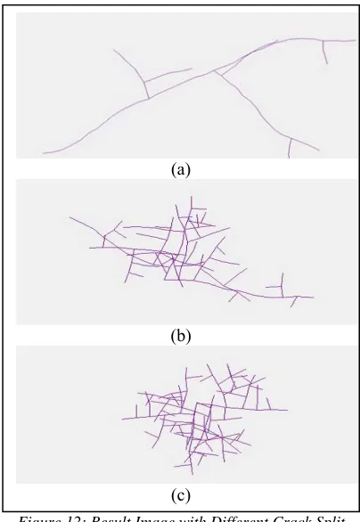
In the first test, the relation between crack split probability and the number of crack segments is evaluated. In this test, the crack split probability value is set from 0.1 to 0.9 gradually. In each step, the value of crack probability value increases 0.1. In every step, 20 running processes are done. The visualization of the number of crack segments with different crack split probability is illustrated in Figure 12. The data that explains the relation
[image:7.612.316.518.126.419.2]between crack split probability and the number of segments are described in Table 2.
Figure 12: Result Image with Different Crack Split Probability
The detail data of the relation between crack split probability and the number of crack segments and the number of crack split actions is shown in Table 2. In this test, the initial energy is set 500. The energy reduction during split activity is set 0.5. The energy reduction during extend activity is set between 5 and 10. In Table 2, nsegment
represents the number of crack segments and nsplit
represents the number of crack activities. The values of the number of crack segments and the crack split activity are the average value for 30 running processes.
Based on data in Table 2, it can be seen that both number of crack segments and number of crack split activities increases while the crack split probability increases. The trend follows linear growth. Because the complexity is measured by the number of crack segments, it can be said that the growth of crack split probability makes the computation complexity grows linearly.
(a)
(b)
5042
Table 2. Relation Between Crack Split Probability, The Number of Crack Segments, and The Number of Crack
Split Activities
psplit nsegment nsplit
0.1 74.9 7.9
0.2 81.8 14
0.3 90.3 21.3
0.4 96.7 27.1
0.5 105.7 35.4
0.6 112.3 42.1
0.7 120.6 50.8
0.8 124 55.7
0.9 125.4 59.4
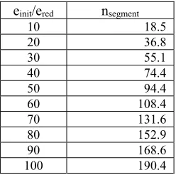
In the second test, the relation between the ratio of crack initial energy to energy reduction and the number of crack segments is observed. The ratio between crack initial energy and energy reduction is symbolized with einit/ered. The ratio
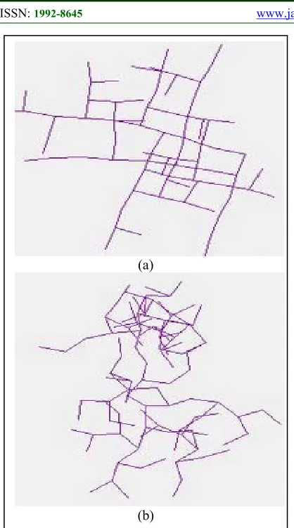
value is set from 10 to 100 gradually with step value is 10. The result is illustrated in Figure 13. The detail data is described in Table 3. In this test, the crack split probability is set 0.5. The energy that is split during split activity is equal between the main segment and the branch segment. In every step, 20 running process is executed. In Table 3, the number of crack segments value is the average value for 20 running processes.
In Figure 13, there are three result images. These images are generated with different einit/ered.
In Figure 13a, 13b, and 13c, the ratios are 10, 50, and 100 consecutively. Based on this visualization, it can be seen that higher ratio produces crack image with more number of crack segments.
Table 3. Relation Between Ratio of Crack Initial Energy to Energy Reduction and The Number of Crack Segments
einit/ered nsegment
10 18.5
20 36.8
30 55.1
40 74.4
50 94.4
60 108.4
70 131.6
80 152.9
90 168.6
100 190.4
Based on the data in Table 3, it can be seen that more ratio of crack initial energy to energy reduction makes the number of crack segments grows. The number of crack segments
[image:8.612.114.278.133.248.2]grows linearly. It means that the linear growth of this ratio makes the computation grows linearly too.
Figure 13: Result Image with Different Ratio of Crack Initial Energy to Energy Reduction
In the third test, the relation between the deviation angle and the total crack length (ltot) is
observed. The deviation angle is half of the gap between the minimum angle (αmin) and the
maximum angle (αmax). The deviation angle is
mentioned in degree. The total crack length is mentioned in pixels. In this test, the deviation angle is set from 10 degree to 90 degree gradually with the step is 10. The crack segment length ranges from 20 to 25 and follows uniform distribution. In each step, ten running processes are executed. The result image can be seen in Figure 14. The detail data is described in Table 4.
(a)
(b)
[image:8.612.133.257.542.665.2]5043
Figure 14: Result Image with Different Deviation Angle
Table 4. Relation Between Deviation Angle and Total Crack Length
αdev (°) Average Total Crack Length (pixels) Minimum Maximum
10 397 313 473
20 404 323 519
30 381 322 455
40 394 335 452
50 372 250 450
60 381 328 473
70 352 283 421
80 337 288 395
90 313 235 375
Based on crack characteristic in Figure 14, there significant difference between crack with low deviation angle and high deviation angle. Figure 14a is example of image result with deviation angle is 10 degree. Figure 14b is example of image result with deviation angle is 90 degree. The crack angle
with low deviation angle tends to right angle and homogenous. The crack angle with high deviation angle has more various angles. Even that, the total crack length difference cannot be differentiated based on the image result.
Based on data in Table 4, there is differentiation total crack length when the deviation angle is grows from 10 degree to 90 degree. When the average total crack length is observed, when the deviation angle is increased linearly, the total crack length tends to be decreased linearly with small gradient. This condition is similar when the minimum and maximum total crack lengths are observed too. The difference is the gradient of maximum total crack length is higher. The gap between the smallest and the highest values of average of total crack length is 91 pixels. The gap between the smallest and the highest values of maximum total crack length is 144.
In the fourth test, the relation between the energy reduction factor during split activity (eredsplit)
and the total crack length (ltot) is observed. The
eredsplit grows from 0.1 to 0.9 with the step value is
0.1. When the eredsplit is 0.1, it means that when the
branching activity occurs, the main segment grabs 10 percents of energy and the branch segment grabs 90 percents of energy. When the eredpslit is 0.9, it
[image:9.612.90.300.523.647.2] [image:9.612.312.523.560.684.2]means that when the branching activity occurs, the main segment grabs 90 percents of energy and the branch segment grabs 10 percents of energy. The crack segment length ranges from 20 to 25 and follows uniform distribution. The deviation angle is set 90 degree. In each step, ten running processes are executed. The result image can be seen in Figure 15. The detail data is described in Table 5.
Table 5. Relation Between eredsplit and Total Crack
Length
eredsplit Average Total Crack Length (pixels) Minimum Maximum
10 333 243 403
20 349 227 460
30 335 279 444
40 311 266 357
50 302 276 343
60 307 234 405
70 352 265 426
80 391 327 451
90 454 351 571
(a)
5044
Figure 15: Result Image with Different eredsplit
Based on the image result in Figure 15, there is different crack propagation characteristic when the eredsplit is different. The Figure 15a is the
result image when the eredsplit is set 0.1 and the
Figure 15b is the result image when the eredsplit is set
0.9. When the eredsplit is low, the crack is more
concentrated. When the eredsplit is high, the crack is
more spread.
The total crack length is more easily observed in Table 5. Based on the data in Table 5, when eredsplit is 0.1, the total crack length is medium
low with the average value is 333 pixels. Then, the total crack length is lower. The lowest value is reached when the eredsplit is 50 to 60 with the average
value is 302 to 307 pixels. After that, the total crack length goes high. The highest value of total crack
length is reached when the eredsplit is 0.9 with the
average value is 454. The situation is similar when minimum and maximum values are observed. The difference is the gap between the highest and the lowest value of maximum total crack length is higher than the average one.
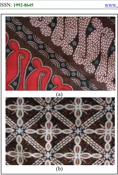
Based on the explanation about the model, implementation, and result data and images, it can be seen that the model has been successfully implemented. The proposed model also has created crack pattern. This model also can be used to generate crack based batik pattern generation. Beside these modifications, improvisation can be more various. It is because there are many batik objects that can be found in the traditional market. For example, set of circles that are placed in the background can be arranged as sinusoid wave. Circle object can also be replaced with other object, such as oval, triangle, or star. The flower object that can be found in Figure 7c is simple flower. So, this flower object can be replaced with the more complicated flower. The object in the node can also be replaced with animal object, such as butterfly, ant, firebird, etc. The example of real batik pattern can be seen in Figure 16. These batiks were bought from Beringharjo souvenir market in Yogyakarta, Indonesia.
There are two traditional batik patterns in Figure 16. In Figure 16a, the pattern is known as Parang. In Figure 16b, the pattern is known as Truntum. In Figure 16a, there are lots of small oval objects. These oval objects symbolized rice seed. They symbolize welfare. These objects are adopted in image result in Figure 7a. Beside the rice seed, there is circular circles object in Figure 14a. This circular circles object is also used in image results in Figure 7b, 7c, 11a, 11b, and 11c. In Figure 16b, there is simple flower object. This flower object is constructed from four oval objects in the top, bottom, left, and right of the center and a circle in the center. This flower object is adopted in image results in Figure 7c, 11a, 11b, 11c. Beside these objects, there are many batik objects that can be adopted from batik in Figure 16, such as: half circle, star, and random size rectangle.
(a)
5045
Figure 16: Traditional Batik Example
Beside these foreground objects, batik is also enriched with background pattern. It can be seen in Figure 16b. In Figure 16b, the background pattern is random abstract objects. This concept is similar and relevant with the background modification as seen in Figure 11.
As a crack model, this proposed model has adopted the physical characteristic of crack. It is similar to the idea in other existing researches in crack modeling. In this proposed model, the higher value of crack initial energy makes the crack grows larger. In the other hand, the crack resistance factor reduces the crack growth probability [3]. The energy reduction variable has the same function with the energy release rate terminology that is used in the existing research [3]. The crack segment length adopts stochastic approach while in some existing research, crack segment length adopted deterministic approach [3]. The crack propagation direction uses continuous approach and it is similar to other existing researches [3,4]. In this proposed model, material surface can be viewed as solid material while other existing research viewed materials as a set of disjoint elements [19].
Even this proposed model has produced crack pattern successfully, there are some
limitations. As a crack model, even this model implements crack resistance factor, this proposed model has not made any differentiation between brittle material and ductile material [18]. In this proposed model, there is not any differentiation about crack behavior during crack propagation phase [3]. In other hand, in the existing research in crack modeling that calculates crack precisely, there is differentiation about crack behavior, especially in crack segment length depended on the crack phase [3].
There are lots of calculation reduction in this model rather than the other existing researches in crack modeling, especially that are implemented in mechanical engineering so that this proposed model cannot be used to predict real crack propagation precisely. As the field of this research is in the graphical computation especially in digital art, the purpose of the research is producing object based on natural phenomenon as real as possible with less computation.
6. CONCLUSION AND FUTURE WORK
Based on the explanation above, the crack model that is proposed in this paper has been able to create crack object and it is used to generate batik pattern successfully. The proposed crack model has been developed bas on graph theory. The proposed model can generate crack pattern that is similar to the crack in the real world. By adjusting parameters in the proposed model, the result pattern can be manipulated so that many crack type can be produced. In this research the crack pattern has been transformed to the batik pattern with some modifications. The modifications are not only in the crack image but also in the background image.
In this proposed model, the crack model has reduced lots of calculations that are used in crack modeling in mechanical engineering field so that the computation is less complex. The advantage is the calculation is light. The weakness is that the proposed model cannot be used to calculate crack in the real world even it can be used to generate crack pattern as digital art. Based on the data testing, when the crack initial energy grows linearly, the number of crack segments grows linearly too. When the crack split probability grows linearly, the number of crack segment and the number of split activities grow linearly too. When the deviation angle grows linearly, the total crack length is reduced linearly. When the energy reduction during split is low, the crack propagation (a)
5046 is more concentrated. When the energy reduction during split is high, the crack propagation is more spread.
In the future, generating batik pattern computationally is still challenging. There are many research potentials in batik pattern generation based on natural phenomena beside living object. Rain, wind, cloud, stone relief can also be used as inspiration. The combination between natural phenomenon and living objects is also challenging. The key point is still creating object as real as possible and in the other hand, reducing calculation is also necessary so that the computation can be reduced as much as possible. Especially in crack modeling, differentiating crack modeling between brittle material and ductile material is interesting.
REFERENCES:
[1] P.D. Kusuma, “Fibrous Root Model in Batik Pattern Generation”, Journal of Theoretical and Applied Information Technology, vol.
24(6), 2017, in press.
[2] P.D. Kusuma, “Fibrous Root Model in Batik Pattern Generation”, Journal of Theoretical and Applied Information Technology, vol.
24(6), 2017, in press.
[3] G. Hutter, Multi Scale Simulation of Crack Propagation in the Ductile-Brittle Transition Region, University of Resources, 2013, PhD Thessis.
[4] T.N. Bittencourt, Computer Simulation of Linear and Non Linear Crack Propagation in Cementitious Materials, Cornell University, 1993, Dissertation.
[5] P. Ljustell, Fatigue Crack Growth Experiments and Analyses – From Small Scale Yielding at Constant and Amplitude Loading, 2013, PhD Thessis.
[6] S. Liu, Y. Lou, H. Wu, K. Teng, D. Chen, “Optimization of Multi-Cluster Fracturing Model Under the Action of Induced Stress in Horizontal Wells”, Journal of Engineering Science and Technology Review, vol 9(2),
2016, pp.59-65.
[7] M.R. Kabir, Modeling and Simulation of Deformation and Fracture Behavior of Components Made of Fully Lamelar γTiAI Alloy, GKSS, 2008, PhD Thessis.
[8] N. Noraphaiphipaksa, A. Manonokul, C. Kanchanomai, “Fretting Fatigue with Cylindrical-On-Flat Contact: Crack Nucleation, Crack Path, and Fatigue Life”,
Materials, vol 10, 2017.
[9] J.H. Norbeck, M.W. McClure, J.W. Lo, R.N. Horne, “An Embedded Fracture Modeling Framework for Simulation of Hydraulic Fracturing and Shear Simulation”,
Computational Geosciences, vol 20(1), 2015,
pp.1-18.
[10]J.J.C. Remmers, R. deBorst, A. Needleman, “A Cohesive Segments Method for The Simulation of Crack Growth”, Computational Mechanics, vol 31, 2003, pp.69-77.
[11]C.A. Duarte, O.N. Hamzeh, T.J. Liszka, W.W. Tworzydlo, “A Generalized Finite Element Method for The Simulation of Three Dimensional Dynamic Crack Propagation”, Computer Methos in Applied Mechanics and Engineering, vol 190, 2001, pp. 2227-2262. [12]D. Chandra, I.S. Putra, A.K. Ariffin, N.A.
Mardi, Y. Nukman, J. Purbolaksono, “Fatigue Growth Analysis of a Surface Crack in Solid Cylinder under Combined Cyclic Axial-Torsion Loading”, Experimental Mechanics,
vol 40, 2016, pp. 1397-1407.
[13]J.A. Nairn, “Simulation of Crack Growth in Ductile Materials”, Engineering Fracture Mechanics, 2004.
[14]H.N. Iben, J.F. O’Brien, “Generating Surface Crack Patterns”, Graphical Models, vol 71,
2009, pp. 198-208.
[15]B. Carter C.S. Chen, P. Chew, N. Chrisochoides, G.R. Gao, “Parallel FEM Simulation of Crack Propagation-Challenges, Status, Perspectives”, Proceeding of Parallel and Distributed Processing, Cancun, 2000,
May 1-5.
[16]R. Citarella, M. Lepore, A. Maligno, Shlyannikov, “FEM Simulation of Crack Propagation in a Round Bar under Combined Tension and Torsion Fatigue Loading”,
Fracture and Structural Integrity, vol. 31,
2015, pp.138-147.
[17]J.F. O’Brien, A.W. Bargteil, J.K. Hodgins, “Graphical Modeling and Animation of Ductile Fracture”, ACM Siggraph, San Antonio, 2002,
July 21-26.
[18]L.M. Torres, Fracture Modeling in Computer Graphics, Universitat de Girona, 2011, Master Thessis.
[19]M. Muller, L. McMillan, J. Dorsey, R. Jagnow, “Real Time Simulation of Deformation and Fracture of Stiff Materials”, Proceedings of
Computer Animation and Simulation,