FIRST ORDER ANALYSIS OF TRUCK PANELS USING STRUCTURAL
SURFACE METHOD
Piong Yee Hwong, Abdul Aziz Hassan and Thiagu Maniam
Faculty of Engineering, University Selangor, Bestari Jaya Campus Jalan Timur Tambahan, Bestari Jaya, Selangor, Malaysia E-Mail: [email protected]
ABSTRACT
Computer Aided Engineering (CAE) has been widely used to evaluate the structural behaviour of an automobile. As CAE can only be operated by well-trained and experienced engineers to yield sensible results, a less complicated and inexpensive tool called First Order Analysis (FOA) is introduced. First Order Analysis has been proposed to verify automobile designs in the initial design stage. Simple Structural Surface (SSS) method and Microsoft Excel are employed as the FOA tools to handle the shortcomings of CAE and to obtain optimal design quickly. The main idea of this paper is to present the graphical interfaces using Microsoft Excel to achieve a product oriented analysis based on the knowledge of mechanics of materials. SSS method is utilized to rationalize the truck panels load path. Force equilibrium equations are established based on the simplifying assumptions to uncover whether the model idealization is statically determinate. Outline of the application of these complementing tools are presented.
Keywords: computer aided engineering, first order analysis, structural surfaces, panels.
INTRODUCTION
Simple Structural Surface (SSS) Method
At the early concept design stage, the available design data often change quickly over a rather short period of time as sales, packaging and manufacturing issues are reconciled and requirements are updated progressively. Various design alternatives may be debated. The design process must consider the structural strength and vibration of the product [1-4]. The design process is in constant change state. For any engineer that is operating in the analysis mode, it is analogous to catch a high speed moving train. Time constraint plays an important role.
Having ‘close to right’ requirements to start with ensure
effective synthesis downstream. These requirements contributed to the global structural specification and guidelines to create the geometry or model for analysis. The simple structural surface (SSS) method, which originated from the work of Pawlowski of the Warsaw Technical University; is offered as a means of organizing the process for rationalizing the basic vehicle body load paths [5]. The vehicle to be modelled using SSS method will be represented using a number of plane surfaces or panels. Each plane surface must be held in equilibrium by a series of forces. These forces are created due to the weight of the components attached to them. The rails that are attached to adjacent plane surfaces would provide reactions to maintain equilibrium. Equal and opposite forces will be exerted to the adjacent members. The loads on each SSS member is propagated through the whole structure from one rail to the other until the overall equilibrium is achieved. This way, any deficiency of the plane structures such as discontinuity in load path can be determined easily. Any SSS that is not supported adequately due to omission of a suitable adjacent component or panel will be revealed. This in turn indicates stiffness deficiency. Types of static loading condition, be
it bending loads, shear loads, tension or compression loads can be identified by the engineer as well.
First Order Analysis (FOA)
There is a vast range of Computer Aided Engineering (CAE) tools offering precision and economy of design in automotive industries [6]. The Structural Dynamics Research Corporation (SDRC, purchased by Siemens AG in 2007) introduced Mechanical Computer
Aided Engineering (MCAE) in the 70’s which has been
widely accepted to date [7]. In order to make sound quantitative judgment, specific knowledge and skills are required for the sophisticated operations of CAE or MCAE. This problem is compounded by lack of legacy data to construct exact geometry or model for analysis in the early design stage. In that, it necessitates the need to entrust a CAE expert. Besides, CAE does not have the ability to maintain and inherit design activities, such as concept design and design know-how. This is because current applications of CAE are based on conventional procedures in which a shape is first obtained and then analysis is performed, and lacking in that they cannot be used to establish a concept before the start of modeling or idealization in CAE.
In this paper, we addressed the above issues by introducing FOA, a complimentary tool to CAE to quickly
estimate ‘close to right’ design before embarking in
transferred to detailed CAE will shorten the process of structural optimization eventually as sensible geometry is
[image:2.595.73.528.141.249.2]provided to start with as shown in Figure-1.
Figure-1. Application of FOA in the product development process.
Load Flow Analysis Using SSS Method
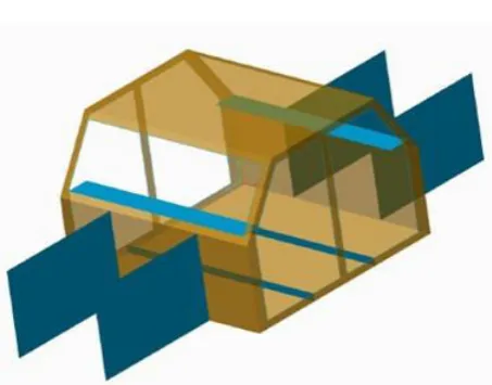
[image:2.595.308.543.367.585.2]The SSS method used prior to and during the initial design stage can complement computer aided design and synthesis notably. In the beginning stage of a new vehicle design, for example as shown in Figure-2, there are normally insufficient data available to develop a complete finite element model for analysis. Model at this stage is generally being represented by sticks or beams and structure surfaces by panels. Figure-3 shows a simplified model of a truck panels to demonstrate the SSS method.
Figure-2. Example of a new vehicle.
Figure-3. Hypothetical truck: SSS idealization.
The truck structure when viewed in side elevation (Figure-4) can be considered as a simply supported beam, the supports are the front and rear axles. Figure-4 also shows the baseline loads that are being considered for the
bending case. These loads are the power-train Fpt, the front
passengers Fpf, the rear passengers Fpr, and the luggage Fl.
Table-1 provides the masses and longitudinal positions of these loads. Subsequently, the front (RF) and rear (RR)
reaction forces can be determined accordingly. Referring to Figure-4, by taking moments about the rear suspension mounting; the front suspension reaction is given by Eqn. (1):
L
d F c L F b L F a L F
RF pt pf pr l
( ) ( ) ( )
(1)
Similarly, taking moments about the front suspension mounting:
L
a F d L F c F b F
RR pf pr l pt
( )
[image:2.595.58.282.406.515.2](2)
Table 1. Masses and longitudinal positions of major loads.
Many more components such as front bumper, radiator, instrument panel, fuel tank, exhaust, rear bumper and distributed loads due to the weight of the structure can be considered to provide a more accurate model. Similar procedure can be applied to calculate the reaction forces.
Free body diagrams and equilibrium equations for each truck panel
Exploded Figure-3 into Figure-5, it can be clearly seen that edge loads and end loads are needed to ensure equilibrium in all SSSs. These loads are represented by the forces K1 to K13. Starting from the central floor cross
[image:2.595.55.282.537.714.2]the passenger loads are taken up by the two transverse floor beams SSS (1) and (2). These floor beams are supported at each end by the side forces K1 and K2, and
there is an equal but opposite force acting on the sideframe. Repeating the same procedure with all the panels, and by using the equations of statics, i.e. resolving forces and taking moments; all the side forces can be determined accordingly.
Figure-4. Major loads distribution.
Figure-5. End and edge loads for bending case in exploded view.
It should be noted that all these loads are applied in the planes of simple structural surfaces in order to ensure sufficient strength and stiffness can be achieved. Based on the shear and bending loads evaluated on each panel, satisfactory stress levels can be assessed. All surfaces are separated and forces that flow between each member are clearly stated. By considering the truck to be in equilibrium condition, equations for the internal forces K1 to K13 are derived based on the relevant forces in each
member as shown below.
Transverse floor beam (front and rear ) Resolving forces vertically and by symmetry:
2 1 p f F K (3) (4) Left and right front inner wing panel and Resolving forces vertically for the left-hand panel:
2 3 pt FL F R
K
(5)
Taking moments about the rear lower corner:
1 1 1 4
)
(
2
h
l
l
F
l
R
K
pt ptFL
(6) Resolving forces horizontally:
(7)
Dash panel
This SSS is subjected to equal and opposite reaction forces from the wing panels, K3.
Resolving forces vertically and by symmetry:
3
6
K
K
(8) Front parcel shelf
This SSS is subjected to equal and opposite reaction forces from the inner wing panels, K4.
Resolving forces vertically and by symmetry:
4
7
K
K
(9) Rear quarter panels and
Resolving forces vertically for the left hand panel:
2
8 l RLF
R
K
(10)
Taking moments about the front lower corner:
2 2 1 2 9
)
(
2
h
l
l
F
l
R
K
lRL
(11) Resolving forces horizontally:
10 9
K
K
(12) Panel behind the rear seats (rear firewall) Resolving forces vertically and by symmetry:
8
11
K
K
(13)
Resolving forces vertically and by symmetry:
9
12
K
K
(14) Floor panel
Resolving forces horizontally:
(15)
Left-hand and right-hand side frames and Both side frames are loaded identically. Examining the forces acting on the side frames, it is obvious that these forces can be obtained from equations (3), (4), (8), (9), (13), (14), and (15). It is essential to use the equations of statics to check if the equilibrium conditions are satisfied. Resolving forces vertically:
0
2 1 116
K
K
K
K
(16) Resolving forces horizontally:
0
12 137
K
K
K
(17) For this bending case, windscreen frame , roof panel , and backlight SSSs are not taking up loads.
The above simultaneous equations (relatively
‘sparse’) can be solved using Microsoft Excel
mathematical modeling and solving technique [8] or alternatively, they can be rearranged and put in matrix form to be solved using Gaussian reduction method, they are:
SSS linked with Microsoft Excel
Embedded CAD model drafting with Excel is one of the Excel features that let the user to link the data between CAD and Excel. AutoCAD drawings, pictures, and clip art of an existing Visio drawing can be inserted by using commands on the Insert menu. Visual Basic for Application (VBA), a macro language in Microsoft Excel, is used to perform functions such as (i) reading and writing data; (ii) transfer to other sheets; (iii) numerical calculations; (iv) import from and export to external files; and (v) initiate an external program.
Graphical user interface (GUI) created using Excel allows simulating specific pathways of interest by prompting for inputs and presenting results only relevant to those pathways. It works by receiving inputs from the user through option buttons, slider bars, check boxes, and input text boxes. Subsequently, communicates the inputs to an underlying Excel spreadsheet model [9-10]. At last displays results in the form of tables in another Excel output file. When designing the GUI for this system, it is easy and efficient to investigate problems encountered as it is possible to switch among the individual sheets quickly in the workbook when editing the spreadsheet. Figure-6 shows the CAD embedded truck panels in Excel. Clicking
‘External forces’ text button will open up the sheet that used to determine the external forces for the baseline model. By manipulating the slider bars on the External forces sheet, the value of the major loads such as power train, luggage load, as well as the panel dimensions would be changed accordingly. Internal forces would be displayed by clicking the relevant text button such as front transverse beam.
Figure-6. Truck panels embedded in Excel linked with SSS.
Figure-7. Shear force and bending moment of front transverse beam.
CONCLUSIONS
From the shear and bending moment diagrams computed using SSS linked with Excel, maximum moment and shear forces are then determined to evaluate the minimum moment of inertia that the panels must be designed for. Areas that require reinforcement or enlargement are revealed. It is also obvious that only basic equations are used to provide appropriate sections for the above mentioned loadings. This approach is applicable for visualizing internal load path when only limited information such as length, height, external load inputs about the vehicle body structure are available since very
basic parameters are known or estimated especially during the initial design stage. FOA using Excel can be used as a template for any new designer to reveal the internal load path at the design concept stage and during the ongoing evaluation stage by CAE. GUI that is developed in Excel embedded with calculation results for the panels or models
mimic the designer thinking process and to address ‘what if’ scenario throughout the product development cycle.
REFERENCES
[1] M. S. M. Sani, M. H. A. Rasid, M. R. M. Rejab, M. M. Noor, K. Kadirgama and M. M. Rahman. 2009. Experimental Study on Noise Source Identification of Split Unit Air Conditioner System. In: International Conference on Advance Mechanical Engineering.
[2] S. K. Reddy, G. V. R. Murty and K.V. Sharma. 2011. Aerodynamic studies in static components of a centrifugal compressor stage. Journal of Mechanical Engineering and Sciences. Vol. 1, pp. 75-86.
[3] K. J. T. Jeffrey, F. Tarlochan and M. M. Rahman. 2011. Residual strength of chop strand mats glass fiber/epoxy composite structures: effect of temperature and water absorption. International Journal of Automotive and Mechanical Engineering Vol. 4, pp. 504-519.
[4] M. S. M. Sani, M. M. Noor, M. S. M. Zainury, M. R. R. Rejab, K. Kadirgama and M. M. Rahman. 2010. Investigation on Modal Transient Response Analysis of Engine Crankshaft Structure. WIT Transactions on The Built Environment. Vol. 12, pp. 419-428.
[5] Jason C. Brown, A. John Robertson and Stan T. Serpento. 2002. Motor vehicle structures concept and fundamentals. SAE International. Inc. pp. 1
[6] Yoshio Kojima. 2000. Mechanical CAE in automotive design. R & D Review of Toyota CRDL Vol. 35 No. 4.
[7] Information on http://en.wikipedia.org/wiki/SDRC (Accessed 30 April 2014).
[8] Brian Albright. 2010. In: Mathematical modeling with Excel. Jones and Bartlett Publishers. Pp. 267-278.
[9] Hidekazu Nishigaki. 2001. First order analysis for automotive body structure design using Excel. R & D Review of Toyota CRDL Vol. 37 No. 1.