© Associated Asia Research Foundation (AARF)
A Monthly Double-Blind Peer Reviewed Refereed Open Access International e-Journal - Included in the International Serial Directories.
Page | 16
AUTOMATED WATER LEVEL CONTROLLER
Ahmad M. Y. Jumba
Department of Electrical Electronic Engineering Technology, Federal Polytechnic, Bauchi, Nigeria.
Bala Hussaini
Department of Electrical Electronic Engineering Technology, Jigawa State Polytechnic Dutse, Nigeria
ABSTRACT
Water is an essential ingredient for daily life and a scarce natural resource despite its usage.
The excessive water usage either for domestic, commercial or industrial purposes, coupled
with Man-made climatic change and pollution has led to water shortage; hence, previous
civilizations have vanished from lack of water (due to droughts). To control and manage the
utilization of water at different sectors, electronic system was designed by using discrete
component known as an analog device. The shortcoming of most of this discrete
components-based system is two levels, to obtain a multiple levels system a microcontroller has to be
employed. This research works with a microcontroller based multi levels water supply and
control device with alarm and digital display which was designed and implemented for
suitable residential, commercial and industrial users.
Keywords: Water, Microcontroller, Pollution, shortage 1.0 Introduction
The world today is facing an excessive water usage either for domestic, commercial or industrial purposes. It is a scarce natural resource, coupled with Man-made climatic change and pollution that can lead to water shortage. Previous civilizations have vanished from lack of water (due to droughts). Some researchers believe the third world war may erupt due to the
GE-International Journal of Engineering Research
ISSN(O): 2321-1717, ISSN(P): 2394-420X Impact Factor- 5.613, Volume 6, Issue 5, May 2018 Website- www.aarf.asia, Email : [email protected] , [email protected]
© Associated Asia Research Foundation (AARF)
A Monthly Double-Blind Peer Reviewed Refereed Open Access International e-Journal - Included in the International Serial Directories.
Page | 17
usage of water and therefore; it is, important to properly use and manage our water usage in different sectors in order to sustain our environment. To control and manage the utilization of water at different sectors, electronic system was designed by using discrete component known as an analog device. The shortcoming of this system is rectifying the usage of digital electronics, particularly the microcontroller-based system.
The microcontroller-based instrument has quickly proved superior to their analog counterparts, such digital systems enjoyed advantaged of extendingfast processing, easier for storage that goes beyond ease of measurement of signal processing and programming. They also allow more rational and effective organization of the countless measurement now required in both domestic and industrial applications.
1.1Background Information 1.2 Principal of Operation
This research work was designed and implemented by using the microcontroller water supply and control device with alarm and digital display for residential, commercial and industrial users. The system was designed to have five levels i.e. 100%, 75%, 50%, 25% and 0%. The pump will come ON when the Water level 25% remaining with an alarm when the level is lower than the setpoint.
2.0 Literature Review
Water supply and control device were designed in the past with a limited number of applications, such as two levels indication of water level inside the reservoir (that is the full and empty level of the water). This approach gives the user very limited information about the water level inside the tanks. The user will not know whether the water level inside the tank is empty, quarter or half. To limit or economize his consumption against running out of the water completely Abdullahi (2013) have designed and achieved a microcontroller-based water level detector with digital display. Yusuf (2013) has also achieved a portable water level indicator, that can be used to detect level of water outside home and at river depth to alert people on the eminent danger of flooding. Similarly, Namuye (2016) had also designed a water level indicator by using raspberry pi, in which multiple levels were achieved and results were displayed by the raspberry pi in terms of exactly percentages.
© Associated Asia Research Foundation (AARF)
A Monthly Double-Blind Peer Reviewed Refereed Open Access International e-Journal - Included in the International Serial Directories.
Page | 18
User Interface (GUI) that convert the output of diesel level analog to digital format so that it can interface with the microcontroller. But it’s too complex and costly. Microcontroller based water supply and control with the digital display were designed with the above mentioned in mind.
However, the problem of the probe in water was tackled through using variable carbon resistor which was placed outside the container, as the water level rise and fall, using floating ball, will converts linear displacement to resistance. The resistance is converted to voltage then amplifier using an op-amp to interface with the microcontroller. This could detect a very small change irrespective of the type of the container used.
2.1 Level Sensor
The level sensor is used to detects the level of water that flow to become essentially in the container (e.g. other physical boundaries) the substance to be measured can be inside a container or can be in its natural form (e.g. rivers or lake). There are many physical approaches to level sensor detection and control which include magnetic and mechanical float, ultrasonic, capacitance, optical interface, hydrostatic pressure and air bubble to mention just a few of them. But for optimal monitoring level monitoring for a domestic, commercial and industrial process the selection criteria include. Physical phase is temperature, pressure or vacuum. While chemistry consideration is the dielectric constant of the medium, density (specific gravity), acoustical or electrical noise and Mechanical criteria include tank shape and vibration. It is also important to design a sensor that provides a shield that protects the float from turbulence or wave motion and it can also operate with a wide variety of liquid.
© Associated Asia Research Foundation (AARF)
A Monthly Double-Blind Peer Reviewed Refereed Open Access International e-Journal - Included in the International Serial Directories.
Page | 19
2.2 The Interface relay
This is an electromagnetic device consisting of a coiled solenoid surrounding a magnetic core that operates a set of electric contacts, in small size and such devices are called contactors. Relay finds application in an automatic control system, in remote control of light, heating control, Automatic load control, and overload protection. When the electromagnetic is energized by a current passing through the coil the amateur is attracted to the magnetic core thereby closing the relay contact, when de-energies the contact are opened by a spring hence the relay act as an electromagnetic switch. Thus, the relay has two main purposes: -
i. The interface relay enables a large circuit and voltage circuit to be controlled by a small current and voltage circuit.
ii. It also enables control circuit to be isolated from the controlled circuit.
2.3 Microcontroller
This is mainly referred to as the heart or brain of the system as a whole. It is responsible for controlling the on/off of the motor and alarm, also feeding the LCD with signal to display the exact replica of the contains of the tanks, in summary, it controls the whole system, the microcontroller is a standalone computer, optimized for control applications, the entire processor, memory and input/output interface are located on a single piece of silicon, so it takes less time to read and write to external device.
© Associated Asia Research Foundation (AARF)
A Monthly Double-Blind Peer Reviewed Refereed Open Access International e-Journal - Included in the International Serial Directories.
Page | 20
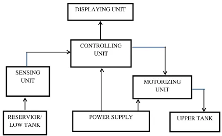
[image:5.595.74.529.74.352.2]3.0 Methodology
Figure 1: Block Diagram of the system
3.1 Memory Organization
There are three memory blocks of the PIC6F876A microcontroller device, which are the program memory and data memory which have separate buses so that concurrent access can occur and EEPROM memory.
3.2 Program Memory
The PIC16f876A have 13-bit program counter capable of addressing 8K word ×14 program memory space. The devices also have 8K word ×14bit of flash programmable memory.
3.3 Data Memory
The data memory is partitioned into four multiple banks which contain general purpose register (GPR) and the special function register (SFR), we can select any bank through bit RP0 and RP1from STATUS register. Each bank extent up to 7FH (128 bytes) with lower locations is for special function registers and the upper is for general purpose registers. The file register can access either directly or indirectly through the file select register (FSR) which is indirect data memory address pointer.
POWER SUPPLY SENSING
UNIT MOTORIZING
UNIT DISPLAYING UNIT
UPPER TANK CONTROLLING
UNIT
© Associated Asia Research Foundation (AARF)
A Monthly Double-Blind Peer Reviewed Refereed Open Access International e-Journal - Included in the International Serial Directories.
Page | 21
3.4 Power Supply Unit
The operator of most electronic equipment requires Voltage, in Nigeria the readily available domestic Power is an outlet, a conversion of this alternating current into unidirectional is therefore necessary. The stage involves include transformation (step down), rectification, filtering and voltage regulation
3.5 Step Down Transformer
This is used to step down the alternating voltage from the higher voltage to lower voltage without a change in frequency, in this case, the to a step down to, which is then rectify and regulated.
Figure 2: Step down Transformer
3.6 The Rectification
Figure 3: Rectification Circuit
The required output voltage is
Diode voltage to turn on is
For the two diode that conduct at each half cycle of the rectifier circuit we have
The transformer secondary output voltage 15v
220V 50Hz
D1 D3
© Associated Asia Research Foundation (AARF)
A Monthly Double-Blind Peer Reviewed Refereed Open Access International e-Journal - Included in the International Serial Directories.
Page | 22
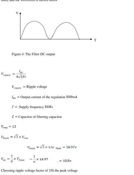
3.7 Filtering Capacitor
[image:7.595.68.525.131.726.2]To smoothen the ripple of the output voltage waveform of the rectification a capacitor is used, and the waveform is shown below
Figure 4: The Filter DC output
Ripple voltage
Output current of the regulation
Supply frequency
Capacitor of filtering capacitor
Choosing ripple voltage factor of the peak voltage
© Associated Asia Research Foundation (AARF)
A Monthly Double-Blind Peer Reviewed Refereed Open Access International e-Journal - Included in the International Serial Directories.
Page | 23
The ripple voltage is given by
3.8 Oscillator
The crystal or ceramic resonator are divided into frequency range
LP lower power crystal
XT crystal/ceramic resonator
HS high speed crystal/ceramic
RC resistor/capacitor
For this project the HS high speed crystal/ceramic is used
F= 1/1.1Re
4m = 1/1.1100KC
C = 2.5 ×10 -11 = 0.25pF.
Since the sink and the source maximum voltage is and , respectively.
Assuming the current of
= 4.2KΩ
© Associated Asia Research Foundation (AARF)
A Monthly Double-Blind Peer Reviewed Refereed Open Access International e-Journal - Included in the International Serial Directories.
Page | 24
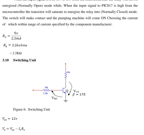
[image:9.595.75.484.49.267.2]3.9 Pump Control
Figure 5: Pump Control unit
When the input signal to PIC 817 is low from the microcontroller the relay will not be energized (Normally Open) mode while, When the input signal to PIC817 is high from the microcontroller the transistor will saturate to energize the relay into (Normally Closed) mode. The switch will make contact and the pumping machine will come ON Choosing the current of which within range of current specified by the component manufacturer.
= 2.2KΩ
3.10 Switching Unit
Figure 6: Switching Unit R1
R2
Rb
AC Supply
Water Pump
12V 12V
MCU
Rb
1.0k
Rc
[image:9.595.64.544.281.729.2]© Associated Asia Research Foundation (AARF)
A Monthly Double-Blind Peer Reviewed Refereed Open Access International e-Journal - Included in the International Serial Directories.
Page | 25
The input can be express as
The diode place across the relay is commutative diode to protect the circuit from back
3.11 Sensing Unit
Figure7: Sensing Unit 2.2k
2.2k
3.3k
15k
10k 5V
5V
© Associated Asia Research Foundation (AARF)
A Monthly Double-Blind Peer Reviewed Refereed Open Access International e-Journal - Included in the International Serial Directories.
Page | 26
For the highest value read from the sensor
For lower value read from the sensor
We need a gain of 5.5 to amplifier the voltage to the desired level
We assumed
While the variable resistor place before the microcontroller is for precision.
3.12 Pump Parameters Pump power = 0.5HP
Suction max =8m
Discharge Head max = 40m Flow 40L/min.
© Associated Asia Research Foundation (AARF)
A Monthly Double-Blind Peer Reviewed Refereed Open Access International e-Journal - Included in the International Serial Directories.
Page | 27
4.0 Test and discussion of result
The various section of the design which are sensing unit, display unit (LCD) unit, switching unit (water pump control) unit, buzzer (alarm) unit, and microcontroller unit, where connected to verify the performance. As expected, certain parameters changed, and some modification was made in the design values, such modification includes the addition of some variable resistor and operational amplifiers to the sensing unit to increase the sensing effect and precision.
4.1 Power Supply Testing
The power supply unit of and was tested for the voltage output under no-load and full-load condition.
At no-load, the voltage of and section was measured to be while that of supply section was measured to be:
At full load, the respective corresponding voltage measured and The percentage voltage regulation is given as
For supply
For supply
The performance of the supply is thus satisfactory since the percentage voltage regulations of the supplies voltage are low.
4.2 Software Testing
© Associated Asia Research Foundation (AARF)
A Monthly Double-Blind Peer Reviewed Refereed Open Access International e-Journal - Included in the International Serial Directories.
Page | 28
4.3 Hardware Testing
The hardware component was assembled on the breadboard and later transfer to Vero board, all connection was checked carefully with the used of digital multi-meter to make sure all connection was made correctly to avoid short-circuiting of the system.
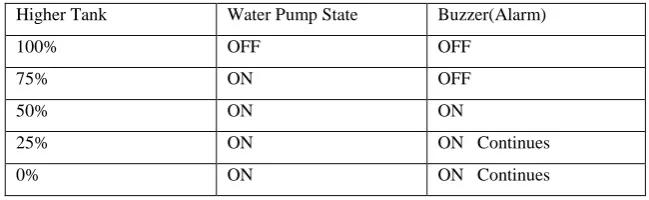
4.4 The Working Principle
[image:13.595.100.425.253.353.2]The working principle is tabulated to ease the understanding of the working operation of the project
Table 1: Working Principle of the System
Higher Tank Water Pump State Buzzer(Alarm)
100% OFF OFF
75% ON OFF
50% ON ON
25% ON ON Continues
0% ON ON Continues
5.0 Conclusion
The aim of the project is to design and implement a microcontroller based automatic water supply and control device with alarm and digital display system to be installed for domestic, commercial and industrial used. The system has been realized to be usable with the device that was found to be working properly based on its design and relatively cheap components involved in its realization. Thus, the aim of the project can be said to have been achieved.
References
Abdullahi, M.A (2012): Design and Construction of Microcontroller based Water Level
Detector with Digital Display. Unpublished thesis Submitted to Electrical Electronics
Engineering Department Federal Polytechnic Bauchi in Partial fulfilment of High National Diploma.
Attia, H. A, Getu, B.N (2016): Automatic Water Level Sensor and Controller System. 6-8
Dec. 2016 IEEE Conference Ras Al Khaimah, United Arab Emirates
Beza N.G, Attia H. A, (2015) Automatic Control of Agricultural Pumps Based on Soil
Moisture Sensing, Proceedings of the IEEE AFRICON 2015 Conference, pp. 667-671, 14-17
© Associated Asia Research Foundation (AARF)
A Monthly Double-Blind Peer Reviewed Refereed Open Access International e-Journal - Included in the International Serial Directories.
Page | 29
Boylestad, R.L, Nashelsky, L. (1996): Electronic Devices and Circuit Theor. Prentice Hall, London.
Forrest, M.M, (1984): Getting Started in Electronic. Oxford University press Inc New York, United States.
Green, D. C. (1982): Digital Electronics Technology. Pitman Publishing Ltd. New Zealand. Namuje, S (2016): Water Level Indicator Using Raspberry Pi. A Mini Project Submitted to
United States International University Africa.
Water and Jobs the United Nations World Water Development Report, 2016, [online]
Available: http://unesdoc.unesco.org/images/0024/002439/243938e.pdf.
Yusuf, M.S (2013): Portable Water Level Indicator. Unpublished Thesis Submitted in Partial
Fulfilment of Requirement for The Bachelor Degree of Electronic Engineering (Industrial
Electronic) Fakulti Kejuruteraan Elektronik dan Kejuruteraan Komputer Universiti Teknikal