4.DataGeneraI
Data General Corporation, Westboro, Massachusetts 01580
Customer Documentation
Programming the Display
Terminal: Models D217,
D413,and D463
Programming the Display
Terminal:
Models D217, D413, and D463
014-002111-00
Ordering No. 014-002111
Copyright © Data General Corporation, 1991 All Rights Reserved
Notice
DATA GENERAL CORPORATION (DGC) HAS PREPARED THIS DOCUMENT FOR USE BY DGC PERSONNEL, IJCENSEES, AND CUSTOMERS. THE INFORMATION CONTAINED HEREIN IS THE PROPERTY OF DGC, AND THE CONTENTS OF THIS MANUAL SHALL NOT BE REPRODUCED IN WHOLE OR IN PART NOR USED OTHER THAN AS ALLOWED IN THE DGC IJCENSE
AGREEMENT.
DGC reserves the right to make changes in specifications and other information contained in this document without prior notice, and the reader should in all cases consult DGC to determine whether any such changes have been made.
THE TERMS AND CONDITIONS GOVERNING THE SALE OF DGC HARDWARE PRODUCTS AND THE IJCENSING OF DGC SOFTWARE CONSIST SOLELY OF THOSE SET FORTH IN THE WRITTEN CONTRACTS BETWEEN DGC AND ITS CUSTOMERS. NO REPRESENTATION OR OTHER AFFIRMATION OF FACT CONTAINED IN THIS DOCUMENT INCLUDING BUT NOT LIMITED TO STATEMENTS REGARDING CAPACITY, RESPONSE-TIME PERFORMANCE, SUITABILITY FOR USE, OR PERFORMANCE OF PRODUCTS DESCRIBED HEREIN SHALL BE DEEMED TO BE A WARRANTY BY DGC FOR ANY PURPOSE, OR GIVE RISE TO ANY LIABILITY OF DGC WHATSOEVER.
AViiON, CEO, DASHER, DATAPREP, DESKTOP GENERATION, ECLIPSE, ECLIPSE MV/4000, ECLIPSE MV/8000, ECLIPSE MV/8000, GENAP, INFOS, microNOVA, NOVA, PBESENT, PROXI, SWAT, and TRENDVIEW are U.S. registered trademarks of Data General Corporation; and
AOSMAGIC, Aos/vsMAGIC, AROSE/PC, ArrayPlus, AV Object Office, AV Office, BBMlJnk, BusiGEN, BusiPEN, BusiTEXT, CEO Connection, CEO ConnectionILAN, CEO Drawing Board, CEO DXA, CEO Light, CEO MAILI, CEO Object Office, CEO PXA, CEO Wordview, CEOwrite, COBOUSMART, COMPUCALC, CSMAGIC, DASHER/One, DASHERI286,DA.SHERI286-12c, DASBERJ286-l.2j,DASBERI3S6, DASBERI386-16c, DASHEHJ386-25, DASHERI386-25k, DASBERJ3868X, DASBERJ386SX-16, DASHER/386SX-20, DASBERl48~5, DASHERILN, DATA GENERAUOne, DESKTOPIUX, 00/500, OO/AROSE, DGConneet, OOIDBUS, DGlFontstyles, DG/GATE, DGlGEO, DGIHEO, DGIL, DGILIBRARY, DGIUX, DGIXAP, ECLIPSE MV/lOOO, ECLIPSE MVI1400, ECLIPSE MVI2000, ECLIPSE MVI2500, ECLIPSE MV/3500, ECLIPSE MV/5000, ECLIPSE MV/5500, ECLIPSE MV/5600, ECLIPSE MVnSOO, ECLIPSE MV/9300, ECLIPSE MVI9500, ECLIPSE MV19600, ECLIPSE MV/lOOOO, ECLIPSE MVI15000, ECLIPSE MV/ISOOO, ECLIPSE MVI20000,
ECLIPSE MV/30000, ECLIPSE MV/40000, FORMA-TEXT, GATEKEEPER, GDCIlOOO, GDC/2400, microECLIPSE, mieroMV, MVIUX, PC IJaison, RASS, REV-UP, SLATE, SPARE MAIL,
SUPPORT MANAGER, TEO, TEOI3D, TEOlElectromcs, TURBO/4, UNITE, WALKABOUT, WALKABOUTISX, and XODIAC are trademarks of Data General Corporation.
UNIX is a U.S. registered trademark of American Telephone and Te1egxaph Company. VP/ix is a trademarlc of Interactive Systems Corporation.
DEC is a U.S. registered trademark of Digital Equipment Corporation. Tektronix is a U.S. registered trademark of Tektronix, Incmporated. MS-DOS is a U.S registered trademark of Microsoft Corpoxation.
AT is a U.S. registered trademarlc of International Business Machines Corporation.
Revision History:
Programming the Display Terminal: Models D217, D413, and D463
014-002111-00
Preface
This manual provides information on the programming environment of the D217, D413, and D463 display terminals. Intended for persons programming host-resident software, this manual was designed as a reference tool and does not explain basic operating functions of these terminals. Refer to Installing and Operating D216E+, D217, D413, and D463 Display Terminals (014-001767) for information on operating one of these terminals.
. This reference manual is organized as described below:
Chapter 1 Characteristics of the programming environment that are common to all operating modes or emulations; everyone should read this chapter.
Chapter 2 Data General native-mode operations and commands. Chapter 3 VT320, VT100, and VT52 emulations and control sequences. Chapter 4 Tektronix® 4010 emulation and commands.
Chapter 5 PCTERM operation and commands. Although PCTERM is actually an operating mode of the VT320/100 emulation, it is covered within its own chapter to avoid confusion within Chapter 3.
Appendix A Tables of all character sets used in any emulation or operating mode.
Appendix B Keyboard layouts for all national-language keyboards supported on these terminals. Appendix C Sample code (in C and FORTRAN 77) that illustrates the programming environment
within several emulations.
Contacting Data General
Data General wants to assist you in any way it can to help you use its products. Please feel free to
contact the company as outlined below.
Manuals
If you require additional manuals, please use the enclosed TIPS order form (United States only) or contact your local Data General sales representative.
Telephone Assistance
options. If you are within the United States or Canada, contact the Data General Service Center by calling 1-800-DG-HELPS. Lines are open from 8:00 a.m. to 5:00 p.m., your time, Monday through Friday. The center will put you in touch with a member of Data General's telephone assistance staff who can answer your questions.
For telephone assistance outside the United States or Canada, ask your Data General sales representative for the appropriate telephone number.
Joining Our Users Group
Please consider joining the largest independent organization of Data General users, the North
American Data General Users Group (NADGUG). In addition to making valuable contacts, members receive FOCUS monthly magazine, a conference discount, access to the Software Library and
Electronic Bulletin Board, an annual Member Directory, Regional and Special Interest Groups, and much more. For more information about membership in the North American Data General Users Group, call 1-800-877-4787 or 1-512-345-5316.
End of Preface
Contents
Chapter 1 -
Introduction
Terminal Features ... 1-2
Enhancements for the D413.D463 . . . 1-3 Supported Emulations and Modes . . . 1-3
Summary of On-Line Operations... 1-4
Communications Interface ... 1-4
Input Buffer. . . 1-4
Flow Control ... 1-5
The Character Generator ... . . . 1-5 25th Row Support.. . . .. . . ... . .. . . . ... . ... . . .. . . ... . .. .. . . 1-6 Term-Server Support. ... . . ... . . .. . . . ... .. . . .. . . .. .. . . .. . .. . . .. . . 1-6
Chapter 2 - Data General Native-Mode
Data General Native-Mode - Summary of O.perations ... 2-1
Data General Native-Mode Features ... 2-4
Keyboard Character Generation ... 2-4
Forming Command Arguments ... 2-7
Recovering a Decimal Value for Command Arguments . . . 2-9
Forming Location Arguments ... 2-10
Recovering a Decimal Value for Location Arguments. . . .. .. . . .. .. .. . . 2-12 Character Sets . . .. . . . 2-13 Hard Character Sets. . . 2-13 Soft Character Sets. . . 2-15 Graphics. . . . .. . . .. . . .. . . .. . . . .... . . .. . . .. . . .. .... . . . .. . . .. . . 2-17 The Graphics Coordinate System ... 2-17
Graphics Cursor ... 2-18
Windows ... 2-19
Lead-In Codes . . . 2-19 UNIX Support . . . 2-20
Debugging Support . . . 2-23 Dual Emulation Support ... 2-23
Data General Native-Mode - Commands . . . .. 2-25
Fonnat of Command Listings in this Section ... 2-26 Command Syntax and Code Conventions ... . . . 2-26 Character Set Commands. . . 2-27 Select Character Set . . . 2-28 Shift Out . . . 2-28
Shift In ... 2-28' Deallocate Character Sets ... 2-28 Define Character ... 2-29 Reserve Character ... 2-29 Read Characters Remaining ... 2-30 Character Attribute Commands. ... . ... ... .... . . .. .. . .... ... ... .. . . .. . . .. 2-31 Change Attributes ... 2-31 DimOn... 2-32 Dim Off .. . . 2-32 Blink On ... 2-32
Blink Off . . . . .. ... . .. . . ... . . .... . . .. .. . . . .. .. . . . ... .. . . ... . . .. . . .. 2-32 Blink Enable . . . 2-32 Blink Disable ... 2-33 Underscore On ... 2-33 Underscore Off ... ',' . . . ... . . . .. .. . . .. .. .. .. ... . . . ... . . . .. . . ... . 2-33 Reverse Video On ... 2-33 Reverse Video Off . . . 2-33 Protect On .. . . 2-34
Protect Off . . . • . . . 2-34 Protect Enable ... 2-34 Protect Disable ... 2-34
Double HighIDouble Wide ... 2-35 Field Attributes. . . 2-35 Page Attributes . . . 2-36 Relative Cursor-Positioning Commands . . . 2-37
Cursor Right . . . 2-37 Cursor Left ... 2-37 Cursor Up ... 2-37 Cursor Down . . . 2-38 New Line . . . 2-38 Carriage Return ... 2-38 Margins Commands ... 2-39 Set Margins . . . 2-39 Set Alternate Margins ... 2-39
Restore N orIllal Margins ... 2-40
Screen Management qommands ... 2-41
Write Window Address. . . 2-41 Window Home. . . 2-42 Set Windows ... . . 2-43
Set 25th Line Mode ... 2-44
Push... 2-44
Pop... 2-45
Write Screen Address . . . 2-46 Select Compressed Spacing . . . 2-47 Select N OrIllal Spacing . . . 2-48
Named Save/Restore Cursor ... 2-48
SaveJRestore Screen Contents . . . 2-49 Screen Home .. . . 2-49 Set Row Length. . . 2-51 Scrolling Commands . . . 2-51
Show Columns ... 2-51
Set Scroll Rate ... :.. 2-51 Scroll Down . . . 2-52
Scroll Up ... 2-52
Scroll Left ... 2-52 Scroll Right . . . 2-53
Roll Enable ... 2-53
Roll Disable . . . 2-54 Horizontal Scroll Disable ... . . 2-54 Horizontal Scroll Enable ... 2-54 Editing Commands ... ". . . . 2-55 Erase Window. . . 2-55 Erase Screen . . . 2-55 Erase to End of Line . . . 2-55
Insert Line ... 2-55
Delete Line ... 2-56
Insert Line Between Margins ... 2-56 Delete Line Between Margins ... 2-56 Erase Unprotected. ... ... .... . . . ... . . .. . .. . . . .. .... .. . .. . . .. ... .. . . . .. .. . 2-57 Insert Character . . . 2-57 Delete Character. . . 2-57
Programmable Function Key Commands ... 2-58
Read Screen Address ... 2-63
Read Window Contents. .. .... . . ... . .... . . . ... .. .. ... ... .. . . . ... . . .... 2-63
Read Model ID ...•... 2-64 Read New Model ID ... ; . . . 2-65 Dual-Emulation Support Commands ... 2-67 Hot Key Switch . . . 2-67 Switch Emulation Mode . . . 2-67 Set Split Screen Mode ... 2-68 Set First Row To Display .... . . 2-68 Set Device Options .... . . .. . . . 2-69 Miscellaneous Commands ... 2-70 Set Cursor Type ... 2-70 Set Model ID ... '.... 2-71 Set Clock Time ... ' 2-71 Bell ... 2-71 Reset... ... .. . . ... .. .. .. . . .... ... ... ... . ... .. ... ... .. . ... .... . . .... 2-71 Select 7/8 Bit Operation. . . .. . . 2-72 Set Keyboard Language . . . 2-72 tJNIX Mode . . . 2-73
Drawing Commands ... . . . 2-74 Line ... 2-74 Arc ... ... 2-75 Bar ... '" .. ... .. . ... .. . .. . . .. .. . . .. . ... .. . . ... . . .... 2-75 Polygon Fill . . . 2-76 Set Pattern ... 2-76 Set Foreground Color .. . . 2-77 Graphics Cursor Commands ... 2-78 Read Cursor Location.. . . ... . .. . ... . ... . . .. ... .. .. . . . .. ... . . . . ... . . .. . . 2-78 Cursor On ... 2-78 Cursor Off . . . 2-78 Cursor Location ... 2-79 Cursor Track . . . 2-79 Cursor Attributes ... 2-80 Cursor Reset . . . 2-80 Printer Commands ... 2-81 Print Window ... 2-81 Print Form ... 2-81 Form Bit Dump. . . 2-82 Window Bit Dump ... 2-83 Print Pass Through On ... 2-84 Print Pass Through Off ... . . . 2-84 Printer Pass Back To Host . . . 2-85 Simulprint On . . . 2-85
Simulprint Off. . . 2-86
VT-Style Autoprint On ... 2-86
VT-Style Autoprint Off ... . . . 2-86 Select Printer National Character Set ... 2-87
Debugging Commands ... 2-88
Data Trap Mode ... 2-88
Diagnostic Commands ... 2-89
Read Cursor Contents ... 2-89
Read Bit Contents ... 2-90
Character Loopback ... 2-90
Fill Screen With Character ... 2-91 Fill Screen With Grid. . . 2-91 Display Character Generator Contents. . . 2-91 Perform UART Loopback Test. . . .. . . .. . . .. . . 2-91
Chapter 3 -
VT320/100/52 Emulations
VT320/100 Emulation - Summary of Operations ... ... . 3-3
VT320/100 Emulation Features . . . 3-4 ,
Control Codes ... 3-5
Received Control Codes ... 3-5
Transmitted Control Codes ... 3-8
Using B-bit Code in 7-bit Environments ... 3-12 Control Sequences . . . 3-13 Escape Sequences. . . 3-13 Device Control Strings. . . 3-13
Generated Keyboard Codes ... 3-14
Character Sets . . . 3-17 Hard Character Sets . . . 3-17 Soft Character Sets. . . 3-20
ANSI Standard Mode Switches ... 3-23
VT320/100 Emulation - Control Sequences ... 3-29
Format of Control Sequences in This Section ... 3-30 A Note on Syntax Conventions. . . 3-30 Hard Character Set Control Sequences . . . 3-31 Sequences for Designating Character Sets. . . 3-31 Assign User-Preferred Supplemental Set (AUPSS) . . . 3-32 Sequences for Invoking Character Sets. . . 3-32 Shift In (SI) . . . 3-32 Shift Out (SO) . . . .. '. . . . 3-32 Shift Lock Two (SL2) ... 3-33 Shift Lock Three (SL3) . . . 3-33 Shift Lock G 1 GR ... 3-33 Shift Lock G2 GR ... . . . 3-33
Shift Lock G3 GR ... 3-33
Single Shift Two (SS2) . . . 3-34 Single Shift Three (SS3) . . . 3-34 Soft Character Set Control Sequences . . . 3-35 Sequences for Downloading Soft Characters (VT320) ... 3-35 Sequences for Clearing Downloaded Soft Character Sets ... 3-36 Attribute Control Sequences ... 3-37 Line Attribute Sequences . . . 3-37 Character Attribute Sequences ... . . . 3-38 Select Graphic Rendition (SGR) ... 3-38 Select Character Attributes (SCA) ... 3-38 Cursor Positioning Control Sequences. . . 3-39
Cursor Up (CUD) ... 3-39
Cursor Down (CUD) ... . . 3-39 Cursor Forward (CUF) . . . 3-40
Cursor Backward (CUB) ... 3-40
Cursor Position (CUP) ... 3-40 Horizontal and Vertical Position (HVP) ... 3 .. 41 Index (IND) . . . 3-41 Reverse Index (RI) ... 3-41 Next Line (NEL) .. . . 3-42
Save Cursor (SC) ... 3-42
Restore Cursor (RC) ... . . 3-42 Tabulation Control Sequences ... . . . 3-43 Set Horizontal Tab (HTS) ... 3-43 Clear Tab Stops (TBC) ... . . . 3-43
Screen Editing Control Sequences . . . 3-44 Delete Character (DCH) . . . 3-44 Insert Character (ICH) . . . 3-44 Insert Line (IL) ... :-. . . . .. . ... . . 3-45 Delete Line (DL) ... . . . .. . . .. . . . 3-45
Erase Character (ECH) ... 3-45
Erase In Line (EL) ... 3-46 Erase In Display (ED) ... 3-46 Selective Erase In Line (DECSEL) ... 3-47 Selective Erase In Display (DECSED) ... 3-47
Scroll Down (SD)T320 ... 3-48
Scroll Up (SU) . . . ... . . 3-48 ANSI Standard Mode Control Sequences ... 3-49
Set Mode (SM) ... 3-49
Reset Mode (RM) ... 3-49
ANSI Standard Mode Parameters. . . 3-50
Keyboard Action Mode (KAM) ... 3-50
InsertlReplace Mode (IRM) ... 3-50
SendlReceive Mode (SRM) ... 3-51
Line FeedlNew Line Mode (LNM) ... 3-51
ANSI Private Mode Control Sequences . . . 3-52
Private Set Mode (EXSM) ... 3-52
Private Reset Mode (EXRM) ... 3-53
ANSI Private Operating Mode Parameters ... 3-54 Application/ANSI Cursor Keys Mode (ACKM) . . . 3-54
Column Mode (CaLM) ... 3-54
Scrolling Mode (SCRLM) ... 3-55
Screen Mode (SCRNM) . . . 3-55
Cursor Origin Mode (COM) ... 3-55
Set to VT52 Mode ... . . . 3-56 Set Limited Transmit . . . 3-56 Auto Wrap Mode (A WM) ... 3-56
Auto Repeat Mode (ARM) ... 3-57
Print Form Feed Mode (PFF) ... 3-57
Print Extent Mode (PEXM) ... 3-58
Text Cursor Enable Mode (TCEM) ... 3-58
MultilNational Character Set Mode (MNCSM) ... 3-58
Numeric Keypad Mode (NKl\1) ... 3-59
Backarrow Key Mode (BKM) ... 3-59
· Transmission Control Sequences . . . 3-61 Transmit 7-bit Controls. . . 3-61 Transmit 8-bit Controls. . . 3-61 User-Defined Key Control Sequences ... . . . 3-62
User Defined Keys (UDK) ... 3-62
Miscellaneous Control Sequences ... 3-63 Soft Terminal Reset ... 3-61 Hard Terminal Reset.. .. .. ... . .. ... . . . ... . .. ... .. ... . .... .. .. . . .. . . .. . 3-61 Alignment.. .. .. . . . .. ... ... . . . ... . . ... . ... . . .. ... . . .... .. .. . . .. . . 3-61 Display Character Generator Contents . . . 3-63
Set/Report Language ... 3-64
Set Clock Time ... 3-64
Hot Key Switch . . . 3-64 Set Top and Bottom Margins (STBM) . . . 3-65 Bit Dump Screen ... 3':'65
Force Display ... 3-65
Data Trap Mode ... 3-66
Select Active Status Display (SASD) . . . 3-66 Select Status Line Type (SSDT) ... 3-67 Set Conformance Level (SCL) ... 3-67 Set Device Options ... . . . 3-68 Split Screen . . . 3-69 Reporting Control Sequences . . . 3-70 Terminal Identification (DECID) ... 3-70 Device Status Report (DSR) . . . 3-70 Primary Device Attribute Request (DA) ... 3-71 Secondary Device Attribute Request (SDA) ... 3-72 Cursor Position Report (CPR) ... 3-72 User Defined Key Status ... 3-73
Keyboard Language... ... 3-74
Answerback. . . 3-75 Printer Port Status . . . 3-75 Request Terminal State Report (RQTSR) . . .. . . . .. . . .. . .. . . .. .. . . .. .. . . .. 3-76 Restore Terminal State (RSTS) . . .. . .. . .. . .. . . . .. . .. .. .. . . .. . . .. . .. . . 3-76 Request Presentation State Report (RQPSR) .. . . 3-77 Restore Presentation State (RSPS) ... . .. . . 3-79 Request Mode (RQM) ... . . . 3-79 Request User-Preferred Supplemental Set (RQUPSS) ... . . . 3-81
Read Cursor Content ... 3-81
Request Selection or Setting (RQSS) . . . 3-82
Printing Control Sequences ... . 3 - 8 4 Auto Print Mode . . . 3-84
Print Screen ... 3-84
Print Cursor Line ... . . . 3-84 Print Controller Mode ... 3-85
VT52 Emulation Operations and Escape Sequences ... 3·85
Character Sets and Graphics ... . . . 3-86
Keyboard Generated Codes ... 3-87
VT52 Escape Sequences ... 3-89
Chapter 4 - Tektronix 4010 Emulation
Emulation Features ... 4-2
Overview of Operational Modes . . . 4-2
Alphanumeric Mode ... 4-3
Margins . . . 4-3
View and Hold Submodes ... 4-3
Graphic Plot Mode ... 4-4
Using Graphic Plot Mode . . . 4-4
Graphics Input Mode ... 4-7
Alphanumeric Cursor . . . 4-7
Graphics Cursor ... 4-8
Hard Copy Command ... . . . 4-8 Hot-Key Switch. . . 4-9 User Selectable Options ... :... 4-9
Graphic Input Terminators ... 4-9
Line/Local Operation ... 4-9
Data Communication Baud Rates . . . 4-9
Chapter 5 -
PCTERM Operations
Introduction . . . 5-1 Inbound (Terminal to Host) Codes . . . 5-2 Flow Control ... . . 5-2
Keyboard G-enerated Codes ... 5-2
Outbound (Host to Tenninal) Codes ... 5-6
Cursor Addressing ... 5-6
Character Sets ... 5-6
VP/ix getty Setup ... 5-7 Sample terminfo File ... 5-7 Sample VP/ix term File . . . 5-8
Appendix A -
Character Sets
United States ASCII Character Set. . . A-2 NRC United Kingdom Character Set. . . .. . . .. . A-3
NRC French Character Set ... A-4
NRC German Character Set . . . A-5
NRC SwedishlFinnish Character Set ... A-6
NRC Spanish Character Set . . . A-7 NRC Danish/Norwegian Character Set. .. . . .. . . .. . . A-8 NRC Swiss Character Set . . . A-9 NRC Katakana (GO) Character Set ... A-I0 Katakana (Gl) Character Set .... . . A-ll DG International Character Set ... A-12 Word-Processing, Greek, and Math Character Set ... A-13 DG Line Drawing Character Set .... " ... " . . . .. . . .. . . A-14 DG Special Graphics Character Set (PC Characters) . . . A-15 VT Multinational Character Set ... A-16 VT Special Graphics Character Set (VT Line Drawing) . . . A-17 ISO 8859/1.2 Character Set ... A-18 PCTERM Low Character Set (0 hex through 7F hex) ... A-19 PCTERM High Character Set (80 hex through FF hex) . . . A-20
Appendix B -
National Language Keyboards
Canadian/English l07-key Keyboard ... B-2
CanadianlFrench l07-key Keyboard. . . B-2
Danish l07-key Keyboard ...•... B-3
French l07-key Keyboard ... B-3
German 107-key Keyboard ... B-4
Italian 107-key Keyboard ... " . .. . . .... .. .... .. B-4
Katakana l07-keyKeyboard ... ... B-5
Norwegian l07-key Keyboard ... :. .. ... . . ... . .. . . . .. . .. . . . .. ... .. ... . .. B-5
Spanish 107-key Keyboard ... B-6
SwedishlFinnish 107-key Keyboard... . .. . .. .. . . .. .... . . .. .. . . .... . . .. . . B-6 SwisslFrench 107-key Keyboard. . . . .. . .. .. . . .... . . .. . .. .. . .. . . .. .... .... . . B-7
Swiss/German l07-key Keyboard ... :... B-7
United Kingdom l07-key Keyboard... B-8
United States 107-key Keyboard. . . B-8 CanadianlFrench 102-key Keyboard . . . B-9
Danish lO2-key Keyboard ... B-9
French l02-key Keyboard ... B-10
German lO2-key Keyboard ... B-10
Italian l02-key Keyboard. . . ... . .. .. . . . .. .. . .. . . . .... . . .. . .. . . .. . . B-1l . Norwegian 102-key Keyboard ... . . . B-1!
Spanish lO2-key Keyboard ... B-12
SwedishlFinnish 102-key Keyboard ... ,. .. ... . ... . .. .. . . .. . . ... . . ... B-12 Swiss lO2-key Keyboard ... ~ . . . B-13
United Kingdom 102-key Keyboard ... B-13
United States 102-key Keyboard. . . B-14
Appendix C - Sample Programs
Notice... ... C-2
Figure 2-1 2-2 2-3 2-4 2-5 2-6 3-1 3-2 4-1 Table 2-1 2-2 2-3 2-4 2-5 2-6 2-7 2-8 2-9 2-10 2-11 3-1 3-2 3-3 3-4 3-5 3-6 3-7 3-8
xvi
Figures
Combining LSBs to Create Decimal Values for Command Arguments ... . Combining LSBs to Create Decimal Values for Location Arguments ... . Designating Character Sets as GL and GR (Data General Native-Mode) ... . Defining a Soft Character Cell Row ... . Combining <dd> Pairs to Specify a Soft Character ... . The Graphics Coordinate System at Power Up or Reset ... . Invoking Character Sets into GL and GR (VT320/100) ... . Examples of Double-Height and Double-Width Lines ... . The Coordinate System of the Tektronix 4010 Emulation ... .
Tables
2-9 2-12 2-14 2-16 2-16 2-18 3-19 3-28 4-4Keyboard Generated Codes - Function Keys (Data General Native-Mode) ... 2-5 Keyboard Generated Codes - Editing Keypad (Data General Native-Mode) ... 2-6 Keyboard Generated Codes - Cursor Keypad (Data General Native-Mode) ... 2-6 Keyboard Generated Codes - Numeric Keypad (Data General Native-Mode) . . . . .. 2-7 Command Argument Translation (Decimal to DG-Hex) . . . .. 2-8 Location Argument Translation (Decimal into ASCII Characters) ... 2-11 Character Sets Available In Data General Native-Mode ... 2-13 Remapped Key Codes for UNIX Support ... 2-20 Altered Outbound Codes for UNIX Support. . . .. 2-21 Altered Data General Native-Mode Commands for UNIX Support ... 2-21 Control Codes Altered for UNIX Support . . . .. 2-22 All CO and Cl Control Codes ... 3-5 Supported CO Control Codes .. . . .. 3-6 Supported Cl Control Codes ... 3-7 Control Codes Generated from the Editing Keys (VT320/100) ... . . . . .. 3-8 Control Codes Generated from the Cursor Control Keys (VT320/100) . . . .. 3-8 Control Codes Generated from the Auxiliary Keypad (VT320/100) ... 3-9 Control Codes Generated from the Function Keys (VT320/100) . . . .. 3-10 CO Control Codes Generated from the Main Keypad (VT320/100) ... 3-11
3-9 Keyboard Generated Codes - Function Keys (VT320) ... 3-15 3-10 Keyboard Generated Codes - Function Keys (VT100) ... 3-16 3-11 Keyboard Generated Codes - Editing Keypad (VT320) ... 3-16 3-12 Keyboard Generated Codes - Cursor Keypad (VT320 and VT100) . . . .. 3-16 3-13 Keyboard Generated Codes-Numeric Keypad (VT320 and VT100) ... 3-17 3-14 Default ANSI Standard Mode Parameters ... 3-23 3-15 Default ANSI Private Mode Parameters ... 3-25 3-16 Keyboard Generated Codes - Function Keys (VT52) . . . .. 3-86 3-17 Keyboard Generated Codes - Cursor Keys (VT52) . . . .. 3-86 3-18 Keyboard Generated Codes - Numeric Keypad (VT52) . . . .. 3-87 3-19 VT52 Escape Sequences. . . .. 3-88 4-1 Format of the Alphanumeric Cursor Status Byte ... 4-7 4-2 Single Control Codes ... 4-10 4-3 Double Control Codes (Escape Sequences) . . . .. 4-10 5-1 Keyboard Generated Codes - Function Keys (PCTERM) ... 5-3 5-2 Keyboard Generated Codes - Numeric Keypad (PCTERM) ... 5-3 5-3 Keyboard Generated Codes - Editing Keypad with Num Lock Off (PCTERM) . . . .. 5-4 5-4 Keyboard Generated Codes - Editing Keypad with Num Lock On (PCTERM) .. . .. 5-4 5-5 Keyboard Generated Codes - Main Keypad (PCTERM) ... 5-5
Chapter 1
Introduction
This chapter provides a brief introduction to the programming environment of the D217/ D4131D463 line of Data General terminals. This chapter has, the major sections listed below.
Terminal Features
Enhancements for the D4131D463
Supported Emulations and Modes
Summary of On-Line Operations
Communications Interface
Input Buffer
Flow Control
The Character Generator
25th Row Support Term-Server Support
Information on operating one of these terminals is contained within Installing and Operating Your
D216E+, D217, D413, and D463 Display Terminal (014-001767).
Terminal Features
The 02171D413fD463 terminals provides maximum compatibility with both the OASHERJD200 and the expanded set of 0460 primitives for the interactive applications programmer. Listed below are some of the main programming features:
• 25 lines of 80 characters displayed in a 10 x12 dot matrix on the 0217
• 25 lines of 81 characters displayed in a 10 x 12 dot matrix in normal mode on the 04131D463, and 25 lines of 135 characters displayed in a 6 x 12 dot matrix in compressed mode on the 0413/D463 • Bidirectional vertical scrolling on all models
• 0200 upward compatibility on all models
• UNIX®-friendly protocol mode that simplifies terminfo file specifications on all models • OEC® VT320, VT100, and VT52 emulations on the 04131D463
• PCTERM operating mode of VT100 emulation on all models • Full-screen configuration set-up menus on all models • Smooth vertical scrolling on the 04131D463
• Horizontal scrolling across 207 columns on the D4131D463 • Up to 25 scroll areas, or windows on the D4131D463 • Advanced editing features on the D4131D463 • Protected text on the D4131D463
• Tektronix® 4010 emulation on the 0463
• Extended graphics with the Line, Are, Bar, and Polygon Fill commands on the 0463 • Graphics cursor for graphics input, controllable by keyboard or mouse on the 0463 • Page and field attributes
• Double high and dQuble wide rows selectable on all models.
Enhancements for the 0413/0463
The D2171D4131D463 has significant improvements over the previous generation Data General terminals. These improvements allow wider system support and enhanced features:
• New diacritical (Spcl) key sequences allow access (using the ALT key) of new characters in the Data General International (DGI) character set on all models
• ISO 8859/1.2 Latin-l compliant character set available in both Data General native-mode and VT emulations on all models
• Added bell to IBM PC AT style (101 key) keyboard • No downloadable character sets on the D413
• Cmd-Cursor UparrowlDownarrow enables/disables split screen on the D4131D463 and moves the split point up and down
• Cmd-Shift-Cursor UparrowlDownarrow moves the active emulation viewing region up and down
Supported Emulations and Modes
The terminals support the following emulation or operational modes:
• Data General native-mode on all models • VT100/VT52 on all models
• PCTERM (an operational mode of the VT320/100 emulation, PCTERM is treated as a separate emulation in this manual to avoid confusion within the VT3201100 sections) on all models
Summary of On-Line Operations
The terminal consists of two major units: the keyboard and the display unit. The keyboard is an input device that generates ASCII characters that are interpreted by the host computer. The display unit is an output device. It interprets commands from the host to control the screen image. The display unit also serves as a link between the host and any printer attached to the terminal.
Input from the keyboard consists of commands and characters. Characters entered at the keyboard for display must be forwarded to the display unit by the host (in full duplex mode only). Commands are either forwarded to the host or are used to invoke special functions in the host software.
The display unit, responding to the ASCII display and control characters, is primarily an output device for the host. A few of the ASCII character sequences or commands request status or
configuration information from the display unit. In these cases, the display unit also functions as an input device.
Communications Interface
The terminal uses an asynchronous serial communication interface. The host computer and optional printer are connected to the display unit via serial interfaces. You can select the terminal transmit and receive baud rates, and other serial characteristics, through the Configuration Menu (accessed by simultaneously pressing the Cmd and N/C keys on the 107-key, Data General Proprietary keyboard or rightmost Ctrl and Scroll Lock keys on the 1OI-key IBM PC AT-style keyboard). Even though the bit transmission rate is set with the baud-rate settings, compatibility with Data General operating systems requires that the terminal transmit characters to the host at a maximum rate of 60 characters per second (paced transmissions). The actual transmission rate falls below this when baud rates below 600 are selected. The character transfer rate is menu-selectable so that other systems, such as UNIX, can take advantage of unpaced transmissions.
Input Buffer
The terminals process all display characters and most commands within the time it takes to receive them (within 2 ms) when the baud rate is 4800 or less. The terminal uses a 256-byte input buffer to accumulate characters the display unit is unable to interpret immediately. The characters are held in the buffer until the terminal is ready to accept them. This commonly occurs when the
transmission rate is 9600 baud or higher, or when the tenninal performs smooth-scrolling operations.
Flow Control
As the input buffer approaches its capacity, the terminal can automatically issue a Ctrl-S (DC3) to signal the host to stop transmitting characters. A Ctrl-S is sent automatically when the number of characters in the buffer reaches a menu-selected value of 64, 128, or 192. You can also choose in menus not to send any Ctrl-S, regardless of the state of the buffer. If the host does not immediately respond to the Ctrl-S by ceasing the flow of characters, the terminal sends another Ctrl-S after eight more characters have been received, and continues to send a Ctrl-S after each eight characters until either the host responds or the buffer fills. If the buffer fills before the host responds, the terminal sends a Ctrl-S back to the host for every character received. When the input buffer falls to 32 enqueued characters, the terminal sends a Ctrl-Q (DCI) to the host, signaling it to resume transmission. The host should respond before the input buffer empties, to avoid a stuttering effect on the display screen.
The Character Generator
All terminals are equipped with a 512~haracter Character Generator (CGEN), which resides in terminal ROM. All hard (ROM-resident) character sets in any mode or emulation are composed of a subset of the characters in the CGEN. Listed below are the sets of predefined characters that comprise the CGEN:
• U.S. ASCII characters
• Foreign language characters (National Replacement Characters) • Word Processing with math, Greek, forms, superscripts and subscripts
• PC characters • DEC VT characters
• ISO (international) characters
25th
Row Support
All terminals and emulations, except the Tektronix 4010, support a redefineable status line. This means that the status line can be treated as the 25th line on the screen. Thus, when this mode is enabled the screen rows run from 0 through 24, instead of the 0 through 23 range that was standard on previous terminals. Refer to the emulation chapters for additional information on the particular usage of this mode within that emulation.
Term-Server Support
The Cmd-C3 keystroke combination on 107-key proprietary Data General keyboards (or rightmost Ctrl and End keys on WI-key IBM PC AT-style keyboards) generates a special code (IC hex, 034 octal) that we provided for persons using term-servers. This code can be used to initiate a macro inside the term-server that switches to a new host computer and sends a code to the terminal to
change to the appropriate emulation. Allowing the term-server to handle this process keeps the host computer and the emulation mode synchronized. The alternative is having the user manually tell the term-server to change to a new host and then manually change the emulation mode on the terminal. Full details on switching emulations is included within the appropriate emulation chapters.
End of Chapter
Chapter 2
Data General Native-Mode
This chapter provides the programming information for Data General native-mode operations on the D2171D4131D463 terminals. This chapter has two major sections:
Data General Native-Mode Summary of Operations
Data General Native-Mode Commands
Command Syntax and Code Conventions
Throughout this manual, there are certain conventions used whenever Data General native-mode commands are explained or referenced. These conventions are:
• Any value enclosed within angle brackets ( < > ) is in octal,
except
command or location arguments.• Values in the form of <0>, <00>, and <non> are location arguments. These values are always (except in UNIX mode, see Table 2-8) expressed in DG-hex. For more information on conunand arguments (and DG-hex), see "Forming Command Arguments."
• Values in the form of <NNN> are location arguments. These values are always (except in UNIX mode) expressed with ASOI characters from "~' through "_". For more information on location arguments, see ''Forming Location Arguments."
• Spaces are often included within a command to separate characters for clarity. When entering a conunand, do not enter these spaces. If a space is part of a conunand, it will be written as <space>.
Data General Native-Mode
Summary of Operations
This section summarizes the operations information specific to Data General native-mode. This section does not cover format or usage of Data General native-mode commands, which are covered in
"Data General Native-Mode Commands," later in this chapter. This section covers the information listed below:
Data General Native-Mode Features
Command Syntax and Code Conventions
Keyboard Character Generation
Fonning Command Arguments
Fonning Location Arguments
Character Sets
Graphics
Windows
Lead-In Codes
UNIX Support
Host-Programmable Function Keys
Debugging Support
Dual Emulation Support
Information regarding functions of the terminal that apply
to
all modes or emulations is covered in. .
.... ."
. ' ' ~ i:l ~ ,. , .
. ::»..;.: ...
Data General Native-Mode Features
All terminals provide maximum compatibility with the D200 and the expanded set of D400 . primitives for the interactive applications programmer. Listed below are some of the main
programming features of these terminals in Data General native-mode:
• 25 lines of 81 characters displayed in a 10 x 12 dot matrix in normal mode
• 25 lines of 135 characters displayed in a 6 x 12 dot matrix in compressed mode on the D413iD463 • 25 lines of 80 characters displayed in a 10 x 12 dot matrix on the D217
• D200 upwardly compatible with all models
• UNIX-friendly protocol mode that simplifies terminfo file specifications on all models • 25th row can be configured as a status line, an extra screen line, a blank row, or as a host
programmable row on all models
• Supports both IBM PC AT-style (101 key) and Data General proprietary (107-key) keyboards on all models
• IBM PC printer supported in character and graphics modes on all models • IBM PC compatible character set available on all models
• ISO 8859/1.2 Latin-1 compliant character set available on all models • Bidirectional vertical smooth scrolling on the D4131D463
• Horizontal scrolling across 207 columns on the D4131D463
• Up to 25 scroll areas, windows, on the D4131D463 • Enhanced editing commands on the D4131D463 • Protected text on the D4131D463
• Split-screen, dual-host mode on the D4131D463
• Hot-key switch between hosts, or between emulations on a single host, on the D4131D463
• Up to 37 sets of up to 94 characters on the D463, for a total of up to 3504 user-defined characters • Extended graphics with the Line, Are, Bar, and Polygon Fill commands on the D463
• Graphics cursor for graphics input, controllable by the keyboard or a mouse, on the D463
• Page and field attributes • Double high and wide rows
Keyboard Character Generation
Each time you press a key, data is sent to the tenninal. The tenninal interprets this data as either a local key (such as a Shift key) or as a code generating key (such as the character "A"). If a character code is generated, it is either sent on to the host computer, if in on-line mode, or is taken as direct input by the tenninal, ifin off-line mode.
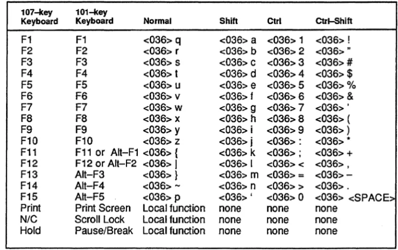
The terminal supports two keyboards, a WI-key keyboard, similar to an IBM-PC AT-style keyboard, and a 107-key Data General standard keyboard. Table 2-1, Table 2-2, Table 2-3, and Table 2-4 show the code generated by each key and recognized keystroke combination on 100-key . and 107-key keyboards. We did not include the code generated by the main keypad because the
generated code is simply the code of the character on the face of the key.
NOTE: The lO7-key keyboard has a Cmd key that does not appear on the WI-key keyboard. To simulate the Cmd key, use the rightmost Ctrl key on WI-key keyboards.
Table 2·1 Keyboard Generated Codes - Function Keys (Data General Native-Mode)
107~ey 101-key
Keyboard Keyboard Normal Shift Ctrl Ctrl-Shift
F1 F1 <03S> q <03S> a <03S> 1 <03S> ! F2 F2 <03S> r <03S> b <03S> 2 <03S> .. F3 F3 <03S> s <03S> c <03S> 3 <03S> #
F4 F4 <03S> t <03S> d <03S> 4 <03S> $
F5 F5 <03S> u <036> e <03S> 5 <03S> % FS FS <03S> v <036> f <03S> S <03S> & F7 F7 <03S>
w
<036> 9 <03S> 7 <03S> ' F8 F8 <03S> x <036> h <03S> 8 <03S> ( F9 F9 <03S> y <036> i <03S> 9 <03S> ) F10 F10 <03S> z <036> j <03S> : <03S> * F11 F11 or AIt-F1 <03S> { <03S> k <03S> ; <03S> + F12 F12 or Alt-F2 <03S>I
<03S> I <03S> < <03S> , F13 Alt-F3 <03S> } <036> m <03S> = <03S>-F14 Alt-F4 <03S> - <036> n <03S> > <03S> .F15 Alt-F5 <03S> p <036> ' <03S> 0 <03S> <SPACE> Print Print Screen Local function none none none
[image:31.615.113.503.346.591.2]Table 2·2 Keyboard Generated Codes - Editing Keypad (Data General Native-Mode)
107-tey 101-tey UNIX Mode
Keyboard Keyboard Normal Shift Normal Shift Erase Page Insert <014> <014> <036> PH <036> PH C1 Home <036> \ <036> X <036> \ <036> X C2 Page Up <036>
1
<036> Y <036>1
<036> Y Erase EOl Delete <013> <013> <036> PE <036> PE C3 End <036> A <036> Z <036> A <036> ZC4 Page Down <036>
-
<036> [ <036>-
<036> [Print Print Screen none none none none
Cmd-Print R.Ctrl-Print Screen <036><021> <036><001> <036>PO <036>P1
Table 2·3 Keyboard Generated Codes - Cursor Keypad (Data General Native-Mode)
107-tey 101-tey UNIX Mode
Keyboard Keyboard Normal Shift Normal Shift Uparrow Uparrow <027> <036><027> <036>PA <036>Pa Rightarrow Rightarrow <030> <036><030> <036>PC <036>Pc leftarrow leftarrow <031> <036><031> <036>PD <036>Pd Downarrow Downarrow <032> <036><032> <036>PB <036>Pb Home nla <010> <036><010> <036>PF <036>Pf
Table 2·4 Keyboard Generated Codes - Numeric Keypad (Data General Native-Mode)
101-key Keyboard 101-key Keyboard 107-key 101-key Mapping with Mapping with Keyboard1 Keyboard Num Lock On Num Lock 002
On Numlock On Off
I / / /
* * * *
- (minus)
-
-
-, (comma) + , ,
. (period) .IDelete Erase EOl
0 Ollnsert 0 Erase Page
1 1/End 1 C3
2 21Downarrow 2 Downarrow
3 3/Pg On 3 C4
4 4/leftarrow 4 leftarrow
5 5 5 Home
6 6/Rightarrow 6 Rightarrow
7 7/Home 7 C1
a a/Uparrow a Uparrow
9 9/Pg Up 9 C2
New Line Enter New Line New Line
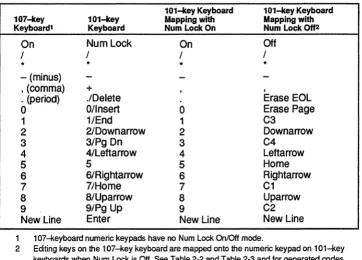
1 107-keyboard numeric keypads have no Num Lock OnIOff mode.
2 Editing keys on the 107-key keyboard are mapped onto the numeric keypad on 101-key keyboards when Num Lock is Off. See Table 2-2 and Table 2-3 and for generated codes.
Forming Command Arguments
Command arguments, are ASCII characters. The majority of arguments in Data General
native-mode commands are composed of either one, two, or three bytes. Each of these arguments are represented respectively by "n", "nn", or "nnn". In command listings, the arguments are always enclosed by angle brackets ( < > ). However, these brackets simply separate the command argument from the surrounding characters. The brackets do not mean that the command arguments are in
octal.
Command arguments are expressed as a version (known hereafter as DO-hex) of standard hex that replaces"N' with ":","B" with ";", "C" with "<", "D" with
"=",
"E" with ">", and replaces"F' with "?".For example, in standard hex, the deci~al value "15" is expressed as "F'. However, in DO-hex, the decimal value "15" is expressed as "1".
..
~ ~
... " :;:..,. "
When command arguments are received by the terminal, the four least significant bits of each byte are concatenated. Thus, an <n> value has four bits; an <nn> value has eight bits; and an <nnn> value has twelve bits. The next section "Recovering a Decimal Value from DO-Hex," has more details on this concatenation process.
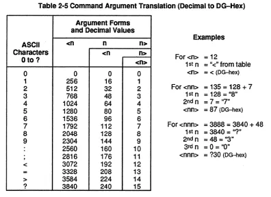
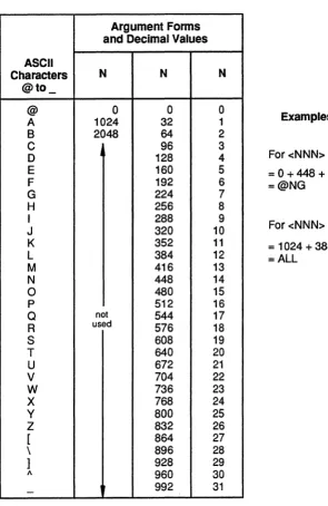
[image:34.612.94.490.199.487.2]Actually forming command arguments is a simple matter of expressing a decimal value in DO-hex. Table 2-5 shows how to change decimal values into DO-hex.
Table 2-5 Command Argument Translation (Decimal to DG-Hex)
Argument Forms and Decimal Values
ASCII <n n n>
Examples
Characters <n n>
Oto? <n> For<n>
=
121st n = "<" from table
0 0 0 0 <n>
=
< (OG-hex)1 256 16 1
2 512 32 2 For <nn>
=
135=
128 + 73 768 48 3 1st n
=
128 = "8"4 1024 64 4 2ndn = 7 ="7"
5 1280 80 5 <nn>
=
87 (OG-hex)6 1536 96 6
7 1792 112 7
8 2048 128 8
For <nnn> = 3888
=
3840 + 48 1st n=
3840=
"?"9 2304 144 9
2560 160 10
, 2816 176 11
2nd n
=
48=
"3" 3rd n=
0=
"0"<nnn>
=
?30 (OG-hex)< 3072 192 12
= 3328 208 13
> 3584 224 14
? 3840 240 15
The largest possible decimal value for <nnn> is 4095. Every value from 0 to 4095 can be expressed as the sum of values that occur in the table, specifically, one value from each of the three columns. However, the decimal value does not determine the form of the argument. Rather, the form of the argument (n, nn, or nnn) determines the range. For example, <n> is always a single byte; <nn> is always two bytes; and <nnn> is always three bytes.
To express a decimal value in DO-hex, follow these steps.
1. Express the decimal value as the sum of up to three values, one from each column, in the table.
2-8
An <n> uses only the rightmost column. An <nn> uses that column and the center one. An
<nnn> uses all three columns. Locate the value in the table that is closest to, but not greater than, the decimal value you want to translate. Subtract the closest value from the original value. Take that difference and find the closest value, but not greater, to it in the table. Continue until you have expressed the original decimal value as the sum of three values from the table.
2. Locate each of the values found in the table and determine what ASCII character represents that value. Once you have determined the appropriate ASCII character for each column, string them together as shown in Table 2-5. The resulting code is in DG-hex.
Recovering a Decimal Value from DG-hex
Some commands return parameter data to the host. In most cases, this data is in DG-hex form and will ned to be converted back. to decimal for application use. For the <n>, <nn>, and <nnn>
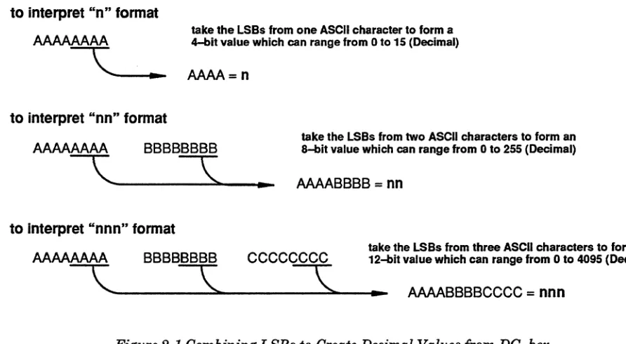
argument forms, only the lower four bits of each argument byte are used. The lower four bits, known as Least Significant Bits or LSBs, of each argument byte are concatenated together to form a 4-bit value for <n>, an 8-bit value for <nn>, and a 12-bit value for <nnn>. Figure 2-1 shows how the argument bytes ( 8--bit ASCII characters) are evaluated.
to interpret "n" format
to interpret "nn" format
take the LSBs from one ASCII character to form a 4-bit value which can range from 0 to 15 (Decimal)
AAAA=n
AAAAAAAA BBBBBBBB take the LSBs from two ASCII characters to form an &-bIt value which can range from 0 to 255 (Decimal)
'----~~---.
AAAABBBB = nnto Interpret "nnn" format
take the LSBs from three ASCII characters to form a AAAAAAAA BBBBBBBB CCCCCCCC 12-bit value which can range from 0 to 4095 (Decimal)
[image:35.612.69.515.305.550.2]'--"-___
3._~
___
3._~___
AAAABBBBCCCC=
nnnForming Location Arguments
Location arguments are used to specifY x- and y-ordinates for graphics commands in Data General native-mode (not, however, in UNIX mode). They are always in the form of <NNN>, where NNN is three ASCII characters from "@"through "_". In commands, the NNN values are enclosed within angle brackets. These brackets are only used in this manual to clearly separate the location argument from the surrounding codes; the brackets do not mean that location arguments are in octal. Forming location arguments is similar to forming command arguments. In both cases, you must express a decimal value as a value containing ASCII characters.
CAUTION: Location arguments in UNIX mode have a different format. Refer to the "UNIX Support" section later in this chapter for details on how UNIX mode uses location arguments.
Location arguments, which always have three bytes, are treated differently than command arguments by the terminal when they are transmitted. Each byte (8-bits) of the argument is truncated by the terminal into a 5-bit quantity by removing the three most significant bits of each byte. Then the remaining three 5-bit quantities are concatenated into a 15-bit value (rather than the 12-bit value in command arguments). For more information on how this concatenation occurs, see the next section "Generating a Decimal Value From Location Arguments."
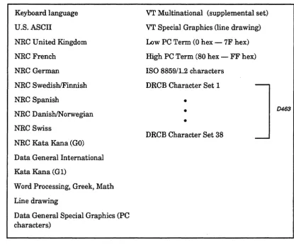
Forming location arguments is similar to forming command arguments. In both cases, you must express a decimal value (ranging from 0 through 3071) as a value containing one or more ASCII characters. Table 2-6 helps you transform decimal values into a form containing ASCII characters.
Table 2·6 Location Argument Translation Table (Decimal into ASCII Characters) ASCII Characters @to_ @ A B C 0 E F G H I J K L M N 0 p Q R S T U V W X Y Z [ \ ] A
-Argument Forms and Decimal ValuesN N
0 0
1024 32
2048 64
96 128 160 192 224 256 288 320 352 384 416 448 480 512
not 544
used 576
608 640 672 704 736 768 800 832 864 896 928 960 992 N 0 1 2 3 4 5 6 7 8 9 10 11 12 13 14 15 16 17 18 19 20 21 22 23 24 25 26 27 28 29 30 31 Examples
For <NNN> = 455 =0+448+7 =@NG
For <NNN>
=
1420=
1024 + 384 + 12 = ALL. '
. " ; : ; : .
. § ~
To express a location argument decimal value into a form containing ASCII characters, follow these steps:
1. Express the decimal value as the sum of three values, one from each column, in the table. Locate the value in the table that is closest to, but not greater than, the decimal value you want to
translate. Then subtract the closest value from the original value. Now take that difference and find the closest value, but not greater, to it in the table. Continue until you have expressed the original decimal value as the sum of three values from the table.
2. Locate each of the values found in the table and determine what ASCII character represents that value. Once you have determined the appropriate ASCII character for each column, string them together as shown in Table 2-6.
Recovering a Decimal Value From Location Arguments
. For location arguments, the terminal sends 15-bits to the host. This 15-bit quantity is interpreted by concatenating the five least significant bits from each of the three bytes that comprise the argument. Figure 2-1 shows how the argument bytes ( B-bit ASCII characters) are evaluated.
location arguments are always in the <NNN> format
AAAAAAM BBBBBBBB CCCCCCCC
C
___
s:.~_~\.
____ ..
take the 5 LSBs from three ASCII characters to form a 15-bit value
AAMABBBBBCCCCC
=
NNNFigure 2-2 Combining LSBs to Create Decimal Values for Location Arguments
As is the case with command arguments, location arguments are also translated into a form containing only ASCII characters. Location arguments use the ASCII characters from "@" to " _" to
express the I5-bit decimal value that results from concatenating the five LSBs of three bytes. Table 2-6 shows the translation values for location arguments.
Character Sets
All terminals are equipped with a 512-character Character Generator (CGEN), which is located within terminal ROM. All hard (ROM-resident) character sets are composed of characters contained within the CGEN. In addition to the predefmed hard character sets, the 0463 supports up to 37 soft character sets (each containing up to 94 characters), which reside in volatile RAM, that are composed of custom characters. Soft character sets store characters within the Dynamically Reconfigurable Character Buffer (DRCB), which contains up to 3504 soft characters.
Hard Character Sets
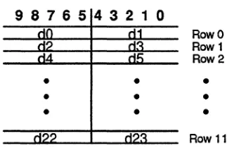
[image:39.615.113.528.337.682.2]Hard character sets are composed of characters located within the CGEN. Two character sets may be selected for use at one time. They are designated as GO (primary) and G1 (secondary). Table 2-7 shows all of the 7-bit and 8-bit character sets available in Data General native-mode.
Table 2-7 Character Sets Available In Data General Native-Mode
Keyboard language U.S. ASCII
NRC United Kingdom NRC French
NRC German
NRC Swedish/Finnish NRC Spanish
NRC
o
ani shIN orwegian NRC SwissNRC Kata Kana (GO) Data General International Kata Kana (G 1)
Word Processing, Greek, Math Line drawing
Data General Special Graphics (PC characters)
VT Multinational (supplemental set)
VT Special Graphics (line drawing) Low PC Term (0 hex - 7F hex) High PC Term (80 hex - FF hex) ISO 8859/1.2 characters
DRCB Character Set 1
-•
•
•
DRCB Character Set 38
GL is used for 7-bit characters (20 hex through 7E hex). The GL character set is generally used with 7-bit sets such as U.S. ASCII or an appropriate National Replacement Character (NRC) set. The NRC sets are language-specific character sets that remap the least used characters from the ASCII set with those characters frequently used within each language. GL can point to GO or Gl.
The GR set is used for 8-bit character codes, which are characters AO hex through FF hex. GR generally contains special graphics sets such as Data General International. GR is hard-wired to
G1.
Powerup Character Sets
During powerup or reset, the terminal initializes the character sets with the default primary (GO)
and secondary (Gl) character sets. If the terminal is operating in 7-bit mode, the GO set is the NRC set and the G 1 set is the word processing set. If the terminal is operating in 8-bit mode, the GO set is the U.S. ASCII set and the G 1 set is the Data General International Set.
Designating Character Sets
Any two of the character sets listed in Table 2-7 may be designated as GO and G 1. The two sets chosen are then designated as either GL or GR. GR is always G1. GL can be either GO or Gl. When operating in 7-bit mode, you must send a Shift Out command to the terminal in order to switch GL from GO to G1. All subsequent characters in GL are selected from G1. In order to return to GO, you must send a Shift In command to the terminal.
When operating in 8-bit mode, G 1 is accessed directly by characters in the range AO hex through FF hex. The Shift. In and Shift Out commands select which character set is to be designated GL (used for characters in the range 20 hex through 7E). Figure 2-3 illustrates which sets can be designated GLorGR.
Sets currently in use
Active
character. sets
GL
7-bit characters(20 to 7E hex)
GO
G1
GR
8-bit characters'---.,..----1 (AO to FF hex)
Figure 2-3 Designating Character Sets as GL and GR (Data General Native-Mode)
Soft Character Sets (0463 only)
CAUTION: Soft character bit patterns in UNIX mode have adiffemet format. Refer to the Unix Support section for a description of how UNIX mode uses bit patterns.
Soft character sets, which contain custom characters, must be defined by the user before they can be used. Creating custom characters and generating character graphics are both functions of the Dynamically Reconfigurable Character Buffer (DRCB). This buffer, which contains up
to
3504 characters, is the industry-standard term for the Down Line Loadable buffer (DLL) used in Data General terminals, such as the D450 and D460.The D463 terminal has up to 37 soft character sets, each of 94 characters. The characters are in the range from 21 hex through 7E hex.
Custom character definitions are valid until the terminal is turned off or reset, or until the
characters are redefined or deallocated. Save your custom character definitions on your host system so they can be easily transferred to the terminal, as needed.
The first step in defining one or more custom characters is to select a DRCB set number using the Select Character Set command. The DRCB set number identifies the character set to contain the custom characters. DRCB sets defined in this way can be designated as the GO or G 1 set, or as both. The D463 uses DRCB set numbers from 20 hex through. 45 hex. Although this range of values is 38 decimal character sets, there is only enough RAM for 37 sets to be in use at one time.
Once you have selected the character set number, you must define the dot patterns for the characters with the Derme Character command. Each character defined fits within a character cell that
Defining Soft Characters
. CAUTION: Soft character bit patterns in Unix mode have a different format. Refer to the "Unix Support" section later in this chapter for details on how Unix mode uses bit patterns.
Soft characters are defined by the Define Character command. This command contains up to twelve <del> pairs, each representing the bit pattern of a character cell row. Each <del> pair, which is a 10-bit quantity, is formed by concatenating the five least significant bits from each of two ASCII bytes. If you are defining a compressed character (character cell size of 6 by 12), only the six most significant bits of the 10-bit quantity are used. Figure 2-4 shows how the <dd> pair is created.
First ASCII character
Second ASCII
76543210 76543210 character
"
9 8 7 6 5 432 1 0<cIc:I> pair (10 bit) formed by concatenating the five LSBs of two ASCII characters
Figure 2-4 Defining a Soft Character Cell Row
Each <del> pair specifies the bit pattern of each character cell row. In each row, the "1's" in the <dd> pair turns screen pixels on and the "O's" turn screen pixels off. For example, the 1O-bit value «dd> pair) 0100000001 turns on the second and last pixel in a character cell row.
Figure 2-5 shows how the twelve <del> pairs defme a DRCB character, where each "d" value is a 5-bit binary quantity.
<del> pair (10 bit) formed by concatenating the five LSBs of two ASCII characters
9 876 5 4 3 2 1 0
Row 0 Row 1 Row 2
•
•
•
•
•
•
•
•
•
[image:42.613.231.393.490.595.2]Row 11
Figure 2-5 Combining <dd> Pairs to Specify a Soft Character
The <dd> pairs are sent to the host in a stream in the order: "dO, d1, ... , d23." Remember, before a DRCB character may be defined, a DRCB character set must be selected as the current (active) character set.
Graphics
The DRCB provides the D463 user with character-graphics commands. In this case, the firmware defines DRCB characters to form the graphic image specified by a given graphics command. The D463 terminal creates graphics displays by combining line segments, arcs, filled polygons, and bars (filled in rectangles) into a composite screen image. The screen image is formed using DRCB
characters defined by drawing algorithms within the terminal.When graphics images are no longer needed on the screen, the DRCB characters used to create them are automatically released and made available for custom characters (described in the previous section).
Character graphics commands supported by the D463 are listed below:
• Deallocate Character Sets - Lets the user free allocated DRCB character sets that were reserved by the Define Character command.
• Bar - Draws solid rectangles of any size, provided they fit entirely within the current window. • Line - Draws lines from point to point within the current window.
• Arc - Draws arc with a specified radius, start angle, and end angle. • Polygon Fill- Draws a filled polygon within the current window. • Set Pattern - Defines the line style used in generating lines.
• Read Characters Remaining - Queries the terminal for a count of the DRCB characters remaining (but reports a maximum of only 1023 characters, even though more may remain).
The Graphics Coordinate System
The Line, Bar, Arc, and Polygon Fill commands are based upon an (x,y) coordinate system, where each point within the graphics coordinate system can be uniquely described by the combination of a horizontal component (the x ordinate) and a vertical component (the y ordinate).
The x-axis is defined by the bottom of the current window. The y-axis is defined by the left margin of the current window. The drawing origin (where x=O and y=O) is, therefore, defined by the
intersection of the left margin and the bottom of the last row in the current window.
Along the x-axis there are 10 x-ordinate units for each of the 81 columns, for a total of 810 units (or 2070 units for 207 columns). Along the y-axis, there are 24 y-ordinate units for each of the 24 rows, for a total of 576 units. Ifhowever, you define the status line as the 25th screen row, then there are a total of 600 units. These dimensions are derived from the 10 by 12 dot matrix in each character cell; one unit in the x-direction for each dot column (10), and two units in the y-direction for each scan row (12).
Yaxis (24 rows)
(0,0)
drawing origin
X axis (80 columns)
(799,575)
[image:44.613.164.435.87.223.2](799,0)
Figure 2-6 The Graphics Coordinate System at Power Up or Reset
The largest possible drawing area consists of the entire display-screen memory, with 24 rows and 207 columns. In this case, the x-ordinate can range from 0 to 2,069; the y-ordinate can range from 0 to 575. The smallest possible drawing area is one character cell (one row by one column). In this case, the x-ordinate can range from 0 to 9 and the y-ordinate can range from 0 to 23.
NOTE:· If the arguments to the Line or Bar commands specify a location or dimension that extends out of the current drawing area, the command immediately aborts.
Graphics Cursor
The graphics cursor, which is available only on the D463, is used to indicate specific points
(coordinates) on the screen by controlling the specified input device. This lets the user identify screen locations easily. The graphics cursor commands are similar to the G300 graphics cursor commands. The D463 does not support a blinking cursor (unlike the G300) and only supports a long crosshair cursor-type. Also, the format of data returned in response to a cursor command is different from the G300.
NOTE: The graphics cursor disappears during both vertical and horizontal scrolling. After the scrolling operation is complete, the cursor will reappear in the same location.
The Read Graphics Cursor command gives you the coordinates of the graphics cursor. Graphics Cursor On and Graphics Cursor Off cause the cursor to appear and disappear from the screen respectively. The Cursor Location command lets you move the graphics cursor to any position on the screen. Cursor Track lets you select what input device will control the graphics cursor. The Cursor Reset command sets the graphics cursor attributes to "off" and "no" tracking.
Windows·
The D4131D463 tenninals provide for up to 24 (25 if 25th Line Mode is set) scroll areas, called windows. Windows may have from 1 to a maximum of25 screen rows. No overlap is permitted. A window does not provide extended or oft'-screen memory in the vertical direction. That is, as text in a window is vertically scrolled up or down, lines at the top or bottom of the window are lost. A window row, however, can contain more than the usual 81 visible columns; a window can be horizontally scrolled over 207 columns. The additional columns are stored within terminal memory.
A new feature of these terminals is an addressable status line. The 25th line of the screen can be blanked, used as an extra screen row, or reserved for the status line. The Set 25th Line Mode command controls the functions of the 25th line on the screen.
Each window is essentially a miniature DASHER D2ID200 screen. D2 commands work within and relative to the current window. This terminal, however, can display up to 81 columns on a screen row.
NOTE: To provide DASHER D2ID200 display compatibility, this terminal initializes the screen to consist of one window with 24 rows of 80 columns. Since all D2ID200 commands work relative to the current window, full compatibility is retained.
Lead-In Codes
Command sequences in Data General native-mode are composed of one or more ASCII characters. Commands composed of at least two characters always begin with 036 octal (IE hex), which is the 2-character command lead-in code. The remaining characters in the command are always printable ASCII characters from 041 octal (21 hex) through 176 octal (7E hex).
UNIX Support
All terminals have a UNIX. mode which remaps troublesome Data General native-mode commands and keyboard codes to allow easier creation of UNIX. terminfo files. This mode is entered and exited via the UNIX. Mode command or the Configuration Menu. For information on using the
Configuration Menu, refer to the manual Installing and Operating D216E+, D217, D413, and D463 Display Terminals.
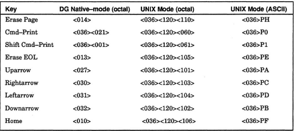
[image:46.615.68.543.257.467.2]Remapped keys that transmit inbound (terminal to host) codes are shown in Table 2-8.
Table 2·8 Remapped Key Codes for UNIX Support
Key DG Native-mode (octal) UNIX Mode (octal) UNIX Mode (ASCII)
Erase Page <014> <036><120><110> <036>PH
Cmd-Print <036><021> <036><120><060> <036>PO Shift Cmd-Print <036><001> <036><120><061> <036>P1
EraseEOL <013> <036><120><105> <036>PE
Uparrow <027> <036><120><101> <036>PA
Rightarrow <030> <036><120><103> <036>PC
Leftarrow <031> <036><120><104> <036>PD
Downarrow <032> <036><120><102> <036>PB
Home <010> <036><120><106> <036>PF
Another change to support UNIX systems involves altered outbound (host to terminal) as well as inbound codes. In UNIX Mode, all Data General native-mode commands accept ASCII coded hex parameters ("0" through "9", "A" through "F', and "a" through "f'), instead of the Data General standard ASCII coded binary parameters and commands that return date will send hex data in upper case. These parameters are encoded as shown in Table 2-9.
Table 2-9 Altered Outbound Codes for UNIX Support
Data General Unix Bits Range
Native-Mode Mode1
<n> <H> 4
o
through 15<N> <HH> 5
o
through 31<nn> <HH> 8
o
through 255<dd> <HHH> 10
o
through 1023<nnn> <HHH> 12
o
through 4095<NNN> <HHHH> 15
o
through 32767<nnnn> <HHHH> 16
o
through 655351 H indicates a hex digit.
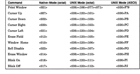
Certain Data General native-mode commands have different structures and codes in UNIX Mode. These changes, shown in Table 2-10, make the remapped keys (see Table 2-8) work in local mode and make some of the terminal descriptions easier.
Table 2-10 Altered Data General Native-Mode Commands for UNIX Support
Command Native-Mode (octal) UNIX Mode (octal) UNIX Mode (ASCII)
Print Window <021> <036><106><077><071> <036>F?9
Cursor Up <027> <036><120><101> <036>PA
Cursor Down <032> <036><120><102> <036>PB
Cursor Right <030> <036><120><103> <036>PC
Cursor Left <031> <036><120><104> <036>PD
Erase Field <013> <036><120><105> <036>PE
Window Home <010> <036><120><106> <036>PF
Roll Disable <023> <036><120><107> <036>PG
Erase Window <014> <036><120><110> <036>PH
Blink On <016> <036><120><111> <036>PI
[image:47.612.53.540.438.695.2]