ISSN: 1992-8645 www.jatit.org E-ISSN: 1817-3195
THE MAGNETIZING CHARACTERISTIC IN THE AIR GAP
OF THE SEIG USING RUNGE KUTTA METHOD AND
CORRECTION FACTOR
1RIDWAN GUNAWAN, 1FERI YUSIVAR , 2BUDIYANTO YAN 1
Department of Electrical Engineering, University of Indonesia, Depok 16424, Indonesia
2
Department of Electrical Engineering, University of Muhammadiyah, Jakarta 10510, Indonesia E-mail:[email protected] [email protected] , [email protected]
ABSTRACT
The Self Excitated Induction Generator (SEIG) is very popular now as a generated alternating power. In this research the induction machine is approached in the physically and mathematically approximated which then transformed from three-phase frame abc to two-axis frame dq using the Park and Clark transformation. Based on the reactive power demand and capacitor mounted on the stator of the induction machine then do the physical and mathematical approach of the system to obtain a state space model. Under known relationships, magnetization reactance and magnetizing current is not linear, so do mathematical approach to the magnetization reactance and magnetization currents characteristic curve to obtain the magnetic reactance equation used in the calculation. Obtained state space model and the magnetic reactance equation is simulated by using Runge Kutta method of fourth order in the exponent equation with correction factor. The influence of the stator current in q axis , is very strong and the equation of this current is non power-invariant then , using take the stator current reference is ⁄ . The correction factor K4 has done the magnetizing inductance Lm and also the output
terminal voltage of SEIG more precision than before.
Keywords : Induction Machine, Self Excitated Induction Generator, dq0 Transformation, State Space, Magnetization Characteristic of Induction Machine, Runge Kutta.Method, Correction Factor.
1. INTRODUCTION
The alternating current machine is known in two type as synchronous machine and asynchronous machine, the synchronous machine is a machine has the rotating rotor and rotating stator flux’s are same. The asynchronous machine is machine, what it has the rotating rotor and rotating stator flux’s are difference. The asynchronous machine is known also as the induction machine, what it do as a generator needed. One of specialty the induction generator from the synchronous generator can operated above synchronous speed , whice known as Self-Excitation. In this condition. The external elements that can change the voltage profile of SEIG are speed, terminal capacitance and the load impedance. In most of SEIG applications, the rotational speed is rarely controllable. Therefore, the load seen by the generator or terminal capacitance has to be controlled [6]. The generator will use the energy, that it generate from rotor rotation for to generate stator flux and rotor flux
using reactive power. The reactive power is given local bank capacitor, that it conected to the stator. This configuration is called as Self Excitated Induction Generator (SEIG). Using the simulation will be done the mathematical approach for hope to achieve a describe about SIEG response . Using the correction factor does the output terminal voltage of SEIG more precision than without the correction factor .
2. METHODOLOGY
The three phase induction generator has some equation. The equation flux average is the flux as time function [1][2]:
The equations stator voltage :
v i r ౩
v i r ౘ౩
v i r ౙ౩
ISSN: 1992-8645 www.jatit.org E-ISSN: 1817-3195
The equations rotor voltage
v ir
౨
್ೝ
ೝ
(2)
The stator and rotor turns flux are written in equation 3 until 5:
λλ
L L
L L
i
i
(3)
λ λ , λ , λ (4)
λ λ, λ, λ (5)
i i , i , i
(6)
i i, i, i (7)
The Inductance stator to stator :
L
L L L L
L L L L
L L L L
(8)
The Inductance rotor to rotor:
L
L L L L
L L L L
L L L L
(9)
The Inductance stator to rotor and rotor to stator:
L L (10) L
cos θ cos θ2π3 cos θ
2π 3
cos θ2π3 cos θ cos θ2π3
cos θ2π3 cos θ
2π
3 cos θ
(11) Where :
L NP : stator self inductance (12)
L NP : rotor self inductance (13)
L NP
cos#2π 3' ( ∶ stator mutual inductance
(14)
L NPcos#2π 3' ( : rotor mutual inductance
(15)
stator to rotor peak mutual inductance
L NNP: stator to rotor peak mutual inductance
(16)
N : stator total turns stator
N: rotor total turns P : air gap permeability
The equation transformation from stator and rotor in *+0 axis is obtained from the Clark and Park transformation and is describe as equation 17.
-fd fq fo1 T
θ-fa fb fc1 (17)
The equation of stator and rotor position θt
θ t 7 ω
tdt θ 0 (18)
θt 7 ω
tdt θ0 (19)
The matric transformation in dq0 axis and its inverse, is shown as in the equations 20-21 : Tθ
23
cos θ cos θ cos θ
sin θ sin θ
sin θ
(20)
the inverse of matric transformation in dq0 axis is
Tθ !
cos θ sin θ 1
cosθ
sinθ
1
cosθ
sinθ
1#
(21)
The stator and rotor voltage in dq0 axis is shown :
v pλ ω λ r i
v pλ : ω λ r i
v
ୱpλ
ୱr
ୱi
ୱ(22)
v pλ ω : ωλ ri
v pλ: ω : ωλ ri
v pλ ri (23)
The flux equation in dq0 axis is shown as
ISSN: 1992-8645 www.jatit.org E-ISSN: 1817-3195
L୪ୱ L୫ 0 0 L୫ 0 0
0 L୪ୱ L୫ 0 0 L୫ 0
0 0 L୪ୱ 0 0 0
L୫ 0 0 L୪୰ L୫ 0 0
0 L୫ 0 0 L୪୰ L୫ 0
0 0 0 0 0 L୪୰
i୯ୱ
iୢୱ
iୱ
i୯୰
iୢ୰
i୰
(24) The stator and rotor flux equations in dq0 axis is :
λ Li Li
λ Li Li (22)
λ Li Li
λ Li Li (26)
[image:3.595.82.506.63.789.2] [image:3.595.309.500.242.324.2]The Self Excitated Induction Generator( SEIG) using capacitors, is the induction generator as noload operation. This system is described as a three phase induction machine symmetrically and connected to identic bank capacitor. The using model induction machine stationery ,will be obtained the equivalent circuit of the self excitated induction generator SEIG in : d-axis, is shown as figure 1 and q-axis is shown as figure 2, as below [4]:
Figure 1 : stasionery circuit at d-axis with excitated capacitor[1] [4]
Figure 2 : stasionery circuit at q-axis with excitated capacitor[1] [4]
From the equivalent circuit as figure 1 and figure 2, is obtained the voltage equations in dq axis :
-v v v v1 =
r Lp
0 Lp 0
0 r Lp
0 Lp
Lp ωL r Lp ωL
ωL Lp ωL r Lp
ii
i
i
(28) The resistance-inductance load RL series , is connected parallel with the capacitor bank Ce.
Figure 3 : The SEIG RLC load[4]
i CpV rpC LpCi (29)
Where :
i i i , and
i rpC LpCi i
i
(30)
v r Lp i or
v
i
(31)Using the the equivalent circuit figure 3 is obtained :
V ౘ!" ౘ
ౘ"! ౘ"మ!# i (32)
The substitution voltage v , v and V , V to equation 28, and then :
-v v v v1
-Z1 i i i i
(33)
-Z1 >Z## Z#
Z# Z? (34) Where :
ISSN: 1992-8645 www.jatit.org E-ISSN: 1817-3195
rୱ Lୱp
rୠ Lୠp
rୠpCୣ LୠpଶCୣ 1
0
0 rୱ Lୱp
rୠ Lୠp
rୠpCୣ LୠpଶCୣ 1
Z# >L0p L0
p?
Z# > L:ωLp ωL
Lp?
Z >r
Lp ωL
ωL r Lp?
The equation 33 is written in the state space model, as below :
p-x1 -A1-x1 -B1-u1
(35)
Where :
The input system is :
-B1-u1 K E
:L 0 L 0
0 :L 0 L
L 0 :L 0
0 L 0 :L
F E v v
v
v
F (36)
And state vector x :
-G1 -i i i i V V i i 1
(37)
K 1 #L⁄ : L . L(:
The plant matric A is shown by equations 38 until 42 :
A K >A## A#
A# A? (38)
A
rL ωL
ωL rL
rL ωLL
ωLL rL
rL ωLL
ωLL rL ωLLrL ωLLrL
(39)
A# E
L 0
0 L
0 0 0 0
:L 0
0 :L
0 0 0 0
F (40)
A
1CK 0
0 1CK
0 0 0 0 0 0
0 0 0 00 0
(41) A 0 0 0 0
1CK 0
0 1CK
1LK 0
0 1LK
0 0 0 0 (42)
The reactance of magnetizing inductance Xm is determined using technical approach with the exponential equation as equation 43 :
J$ KL$ M%⁄ N. OP$ #Q&మ'
మ
P(R (43)
Using the equations of reactance , is done the algorithm of simulation for the self excitated induction generator using the “ Runge Kutta method of Fourth Order”[5] and the exponent equation.
This simulation uses Linear Time-Variying State Model as a discrete computation runge kutta method, and is applicated in the state space equation 44 :
.
xSt fx, t (44)
The state vector x-n : 1T1 xn : 1
and xn ≅ xnT (45) The sampling time T is step interval. The state space counting programme is using the function
fx, t for determine xSt fx, t along state
vector x as a function time t. Using the runge kutta method of fourth order is determined the constant of it method in discrete form equations 46 until 55 :
The state vector derivative VS in discrete form is written as :
xn 1 ≅ xn 1T (46)
fx, t A#xt(-xt1 B#xt(-ut1 (47)
And the plant matric A and the input matric B is written as :
-AnT1 -An1 -AxnT1
-BnT1 -Bn1 -BxnT1 (48)
For n = n+1 then :
-AnT T1 -An 11 -Axn 11
-BnT T1 -Bn 11 -Bxn 11
ISSN: 1992-8645 www.jatit.org E-ISSN: 1817-3195
The Runge Kutta method of fourth order is written
as:
g)≡ f-xn1
g#≡ f Yxn g)O
RZ
g≡ f Yxn g#O
RZ
g(≡ f-xn gT1
g*≡ g) 2g# 2g g( 6⁄ (50)
Renew the state vector in the discrete state equation
xn 1 xn g*T (51)
-An 11 -Axn 11 and
-Bn 11 -Bxn 11 (52)
n n 1 and t nT (53)
xn 1T fxn, nT (54)
fxn, nT
-Axn1-xn1 -Bxn1-un1
(55)
The exponential equation (43) will be search the constant of K1, K2 and K3 , using the range of
magnetizing current $ and the range is :
$'$'+ 100% : Q $' dan
$'$,- 100% Q $' (56)
So that :
$'$'+] $] $'$,-
(57)
Atake the Q^ from 1 percent until 5 percent.
$'$'+ : miminum range $'$,-: maximum range
[image:5.595.92.513.69.791.2]$' : the value $#, $, or $(.
Tabel 1: measurement of the constant K1, K2 and K3 [4].
$
amp
M% Volt
J$
Ohm Constant Formula
i#
i#
V.# a X V #
.#⁄i#
K#
c : K( b
a : b b : cc
*/ *
i
5i#
V. b X V
.⁄i
K
49 24i(1
ln b b : c a : bc
i(
7i#
V.(
c X(
V.(⁄i(
K(
b: ac
2b : a c
3.RESULTS AND ANALYSIS
[image:5.595.307.511.142.344.2]The data of the self excitated induction generator SEIG, three phase 230/400 volt,50 hertz, 2.2 kW / 3 HP, 8.6 ampere, 4 poles, squirrel cage , delta connection [7]
Table 2 : Data of induction generator [7]
magnitd unit magnitd unit
0 3.35 Ohm V-base 230 volt
J0 4.85 Ohm I-base 4.96 amp
1.76 Ohm n-base 1500 rpm
J 4.85 Ohm f 50 hertz
3.1 Simulation using the exponent equation In this simulation is used the magnetizing inductance in exponent equation :
L$ -0.1027 ∗ Q1.3#∗'∗'1 0.0395
Base on using exponent equation that it is iterrated by magnetizing current $ in interval 0.01 A and then determine the exponent equation using the program linear-piecewise equation from relation between the reactance J$and the air gap voltage M% in table 3 as below :
Table 3: the magnetizing reactance Xm [7]
Vumin – Vumax (volt) Xm (ohm)
0 - 117.87 108.000 117.870 - 171.052 135.553-0.233*Vb 171.052 - 211.919 151.160-0325*Vb 211.919 - 344.411 213.919-0.621*Vb
ISSN: 1992-8645 www.jatit.org E-ISSN: 1817-3195
[image:6.595.298.508.146.321.2]
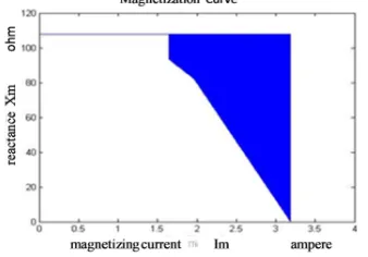
so that is obtained the curve in figure 4, as below :
[image:6.595.94.257.171.277.2]Figure 4: the magnetizing curve using the linear-piecewise
Figure 5 : magnetizing curve using the iteration of magnetizing current +
The magnetizing curve shows that the magnetizing current $ rises to become 1,646 ampere until 3.185 ampere , so that is obtained the constraint of search. From the linear-piecewise equation the minimum value of J$ , it know is 0.2267 ohm , and using the the search of constant program, and than is obtained the magnetizing current maximum
$( is 1,646 ampere.
Tabel 4. Parameter of the induction machine constant
+
amp , (ohm) , 1
amp2 (ohm) ,
, ,
(ohm) 3.15 76.7820 -0.0652 32.227 109.010
3.00 81.5965 -0.0602 27.301 108.898
2.85 93.2129 -0.0507 15.570 108.783
2.80 98.0240 -0.0477 10.723 108.747
2.75 104.347 -0.0442 4.3628 108.710
2.70 107.478 -0.0426 1.2013 108.680
2.69 106.530 -0.0430 2.1454 108.675
2.68 108.439 -0.0421 0.2289 108.668
2.67 0 Infinite 108 108.000
2.66 Not found solution for ,2 / 0
3.2 Simulation using the approach i5 i6789
The relationship between the air gap voltage Vu, terminal voltage Vb, manetizing current $ and capacitance current ic [4] .
The reactance value J$ is counted using air gap voltage M% same as terminal voltage M,0: , 230M as below :
211.919 ≤ M% ≤ 344.411 , Vu = = 213.919 volt
J$ = 213.919-(0.621*230)
J$
:;
71.089 ohm
and than the capacitor value Ce at P( l J$ :;
71.089 ohm is:
m:n
1
NKP
(
Is caused the J$ :;
value greather than the inductance minimum value J$ , then the value of capacitor Ce
m:o 44,8 µFarad
Using the resistance-inductance RL load
p qKL : #1/Km:(
if the load is the resistive load then the reactive load component is zero and is obtained the inductance Lb
[image:6.595.103.272.321.439.2]ISSN: 1992-8645 www.jatit.org E-ISSN: 1817-3195
From , the nominal current generator is 4.96
ampere then the base impedanc s,0: grather than M,0:⁄t,0: and s,0:n 46.371 ohm
For load is one percent s,0: then ,
s,0: 4637.1 ohm
s cos u and the power factor of this load
cos u ≅ 1 dan s,0: then:
≅s,0: 4637.1 Ohm
Using the value m:, L and and the data of constant K1, K2 , K3 and impulse 10 volt
along 0.0003 second until stable condition is obtained the peak value :
Table 5 Data equation approach 0 0.
<0 (ampere)
< (ampere)
M=< (volt)
=< (ampere) 3.5065 0.2349 249.7465 0.0539
3.4793 0.2329 247.8041 0.0534 3.4442 0.2305 245.3062 0.0529 3.4300 0.2295 244.2914 0.0527 3.4169 0.2286 243.3601 0.0525 3.4126 0.2283 243.0553 0.0524 3.4160 0.2285 243.2985 0.0525 3.4125 0.2283 243.0506 0.0524
Can not simulation
From Table 5 the value of load voltage M=< is unequal, with the base voltage M,0: , because the reactance equation J$ does not precise, than the correction technical approach is used.
The stator current in q axis <0, that it the matric equation is non power-invariant then , take :
<0 :;
2 3⁄ t,0: = 3.306667 ampere
The current +in table 5 is grather than the current <0
:;
then is used the correction factor , because in the matric equation -VS1 is consist of the current <0, that it the induction equations .
Using P* <0 :;
<0
' and is multiplied to equation 43 is obtained the new reactance equation using
correction factor.
J$ P*. N. OP#. Q&మ.'
మ
P(R (58)
The repeated this process using the equation 58, and data in table 4 , table 5 and the current value
<0 is obtained the new data in table 6.
Table 6 : The new data using the correction ,.
P* <0 (amp)
< (amp)
M=< (volt)
=< (amp) 0.94301060 3.2548 0.2243 231.8150 0.0500
0.95038274 3.2701 0.2201 232.9028 0.0502
0.96006813 3.2887 0.2208 234.2306 0.0505
0.96404276 3.2937 0.2210 234.5883 0.0506
0.96773879 3.2982 0.2211 234.9075 0.0507
0.96895818 3.2998 0.2212 235.0183 0.0507
0.96799376 3.2991 0.2212 234.9703 0.0507
0.96898657 3.2928 0.2208 234.5206 0.0506
Can not simulation
4.CONCLUSION
. The precision of the magnetizing inductance equation L$ is very important , because these equations influence in determine of the equation in simulation depend on magnetizing current im.. The
output terminal motor voltage very depend on the precise of the magnetizing inductance Lm, magnetizing current im and the air gap between stator and rotor. The influence of the stator current in q axis <0, is very strong and the equation of this current is non power-invariant then , using take the stator current reference <0
:;
is 2 3⁄ t,0: . The correction factor K4 has done the magnetizing inductance Lm and also the output terminal voltage of SEIG more precision than before.
REFFERENCES:
[1] Peter Vas, “Electrical Machines and Drives : A Space Vector Theory Approach”, Oxford University Press, New York , 1992.
[2] Chee-mun Ong, Dynamic Simulation of Electrical Machinery. New Jersey: Prentice Hall, 1998.
ISSN: 1992-8645 www.jatit.org E-ISSN: 1817-3195
function in MATLAB/SIMULINK”. IEEE
Journal 2001.
[4] M.Godoy Simoes and Felix A. Farret, “
Renewable Energy Systems , Design and Analysis with Induction Generators” CRC Press 2004
[5]Shelly Vadhera and K.S. Sandhu, "Estimation of saturation in grid connected induction generator," International Journal on Emerging Technologies, 2010.
[6] Subramanian Kulandhaivelu and K.K. RAYet. “Voltage Regulation of 3-∅ Self Excited Asynchonous Generator” /International Journal of Engineering Science and Technology Vol. 2 (12), 2010, 7215.
[7]K. Trinadha, A. Kumar, and K. S. Sandu, "Study of Wind Turbine based SEIG under,"
International Journal of Electrical and Computer Engineering (IJECE), vol. 2, June 2012.
[8] Ridwan Gunawan, Feri Yusivar and M.Luniara Siregar, “ The Influence of Moment Inertia to Induction Motor Rotation In Sensorless Direct Torque and Duty Ratio”. Applied Mechanics and Materials Vol 313-314 (2013) pp
55-60.Trans Tech
![Tabel 1: measurement of the constant K1, K2 and K3 [4].](https://thumb-us.123doks.com/thumbv2/123dok_us/8911020.959294/5.595.92.513.69.791/tabel-measurement-constant-k-k-k.webp)