Separated Boot Process as of 04/22/85
station Master
1)
<---
Boot phase 1 (to user 254)2) 3)
4)
If a Z80 station, load this in and execute it. Otherwise, run a ROM program that does the same thing, i.e. get ready to react to the poll of the login-user. Set name/psw to the ascii representation of our serial number.
<---
Poll loguser (user 253) login reg(name/psw, binary serial,
product type)
--->
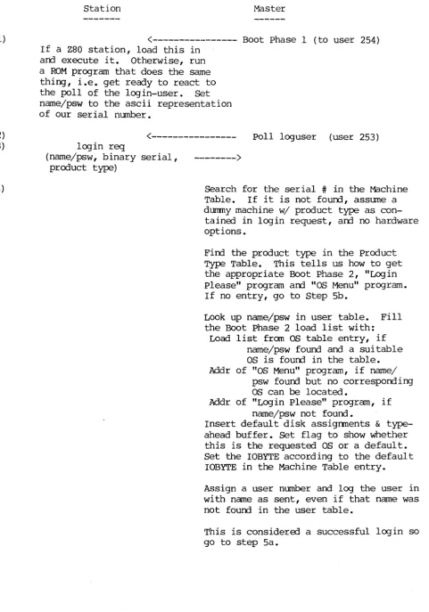
[image:1.617.43.525.72.760.2]Search for the serial # in the Machine Table. If it is not found, assume a dummy machine w/ product type as
con-tained in login request, and no hardware options.
Find the product type in the Product Type Table. This tells us how to get the appropriate Boot Phase 2, "Login please" program and "08 Menu" program. If no entry, go to step 5b.
Look up name/psw in user table. Fill the Boot Phase 2 load list with:
Load list from as table entry, if name/psw found and a suitable as is found in the table. Addr of "OS Menu" program, if name/
psw found but no corresponding as can be located.
Addr of "Login Please" program, if name/psw not found.
Insert default disk assignments & type-ahead buffer. Set flag to show whether this is the requested OS or a default. Set the IOBYTE according to the default
IOBYTE in the Machine Table entry.
Assign a user number and log the user in with name as sent, even if that name was not found in the user table.
Sa) (if all essential table entries or defaults were found)
<---
logack(ack,userno,time,binary serial) (to user 253)5b) (if a crucial table lookup failed so no Boot phase 2 can be sent)
<---
logdeny(deny,userno,time,binary serial) (to user 253)6) If binary serial doesn't match the one Yle sent, or if the "reply" is really a poll, our request was missed. Return to step 2.
7)
If message is a logdeny, we are in serious trouble and should dump serial # (and product type if possible) to screen, with "login denied" message. Die here.
If message if a logack, prepare to get Boot phase 2 under ,the new user number.
<---
Boot phase 2 (to new user number) The first byte of Boot Phase 2 is the number of l024-byte blocks it contains. The station reads the first block, then looks at this length to determine whether there are more coming; if so, it reads them. The station executes Boot phase 2 by jumping to the address following the length byte, i.e. the second byte of Boot phase 2. 8) Boot Phase 2 is a loader for a series of programs and contains theiraddresses, lengths, etc. When run, it will load at least one program (by ordinary HiNet reads). It will transfer control to one of the programs it loads, as detennined by the particular Boot Phase 2 code and by the data inserted into it when it was configured by the Master. The outcome of this loading process will be one of the following: 9a) • If the program Yle loaded is a BIOS, it will run its cold-boot code.
IF WE EVER GET HERE, WE'RE OONE.
*****
9b) • If Yle've actually loaded a "Login Please" program, it will respond to the next poll of our user number with a request to log us out; there-after it will answer no polls of that user number. It will then ask the user for a name and password, which it uses to construct a new log in request.
RETURN TO STEP 2.
****
9c) • If we have an "aS menu" program, it will ask the user to choose among the possible OS's for this machine, and to choose default partition assignments compatible with the selected OS. The program will then reconfigure Boot phase 2 to load the selected as.
System Directory Layout Up to 128 entries.
Each entry is 24 bytes: 8 bytes 5 bytes 2 bytes 4 bytes 2 bytes 1 byte 2 bytes
filename (ASCII)
disk address (v,p,t,s) length (in l28-byte sects) load address
offset to execution address prog/data flag
reserved 128 entries of 24 bytes each: 3k bytes total.
The System Directory describes storage allocation within a large contiguous area; i.e. a portion of Unit 0 is reserved for the exclu-sive use of files pointed to by this directory.
For sllnplicity the 8-character name should correspond to the name of the .COM file created under CP/M.
The disk address contains fields for volume and partition number and these should be filled in even though as of 9/13 we have decided to put all system files in Unit O.
The length field allows programs to load files using this directory and allows utilities to detennine disk usage.
The load address is the address in the host's memory where the program expects to be loaded, and the 2-byte offset is the distance from that point (always non-negative) where execution is to begin.
The prog/data flag has low bit 0 for tables or other data files or 1 for executable code.
A utility which alters or erases any directory entries is responsible for moving the remaining files so that there are no holes in the disk storage area except the one after the last file. This allows the use of a high-water mark entry whose name field is filled with nulls. Each file has one entry in the System Directory and each entry refers to one file. In the future it may be perrnissable to have two or more directory entries that differ only in the load address and name fields,
Product Type Table Layout Up to 40 entries.
Each entry is 25 bytes: 1 byte 8 bytes 8 bytes 8 bytes
Product Type (0 for end) name of Boot phase 2 program for this product type
name of "Log in Please" program name of "aS menu" program 40 entries of 25 bytes each: 1000 bytes (lk allocated.)
Search routines are expected to find a match for seven bits of the Product Number, i.e., they are to ignore the high bit which in some implementations identified a serial or parallel console. The programs which can be found through this table all use PROM console drivers and so are oblivious to the console type.
The names of programs in this table correspond to names in the System Directory.
Machine Table Layout
Up to 128 entries.
Each entry is 12 bytes: 4 bytes 1 byte 6 bytes 1 byte 128 entries of 12 bytes each: 1.5 k.
Serial Number (binary form) Product Number
Option Map IOBYTE
option map will have one bit assigned to each possible device driver, e.g. 5-inch HD with Xebec controller, Port 3 type-ahead, spooler, etc. Machine table search routines will return the product number if the machine is found, or zero if the machine's serial number is not in the
as
Table LayoutUp to 128 entries.
Each entry is 96 bytes: 1 byte 16 bytes
6 bytes 64 bytes
2 bytes 7 bytes 128 entries of 96 bytes each: 12k.
as
Number Product Map Option Map load list(up to 8 fields, each being an 8-character name; list is tenminated by nulls)
Length (in 128-byte records) reservErl
For an OS to be selected, the bit in the Product Map corresponding to the Product Number fran the Machine Table must be "1".
TO be selected, the upper nibble of the BIOS'
as
number must match its counterpart in the User Option Table. The lower nibble of the BIOS' OS number must also match its counterpart in the User Option Table if the latter is non-zero. If the lower nibble in the User Option Table is zero, no test will be made on the lower nibble of the BIOSas
number.(Thus, as a minimum, the BIOS must run the
as
the user requested on the machine the user is using. By allowing a degree of defaulting on theas
type, we allow the autanatic selection of the version of the specifiedas
which will run on the specified machine.)If the User Table entry shows that a "full-service" BIOS is desired, the Option Map from the Machine Table will be matched against the Option Maps in the
as
table. If an exact match is found this is theas
that will be sent. If no exact match is found, or if the user has requesterl a "high-TPA" BIOS, then the anallest BIOS matching theas
and machine requirements will be sent.The "load list" contains the names of any system programs that must be 10adErl in booting this
as,
in the order they are to be 10adErl, starting with the name of theas
itself. For example, a CP/M 2.2 BIOS would have the name of the BIOS first, then the name of the file containing the CCP and BOOS (to be loaded on each wanm-boot.) There can be up to eight files specifiErl in this way (i.e. the file to which this table entry specifically corresponds, plus up to seven others.)User Name Table Layout Up to 128 entries.
Each entry is 16 bytes: 8 bytes 6 bytes 1 byte
1 byte
128 entries of 16 bytes each: 2k.
User Name Password
as
number (upper nibble is the "generic"as
type, lower nibble is specific -- CP/M-80, 86 etc; lower nibblea
means don't care)as
size flag. lower bita
forfull-service
as,
1 for smallest availableas.
This is the same layout as in pre-Separated Boot versions of HiNet, except that the two bytes in each entry previously "reserved" are now used.
User Configuration Table Layout Up to 128 entries.
Each entry is 64 bytes: 8 bytes 8 bytes 8 bytes 8 bytes 1 byte 31 bytes 128 entries of 64 bytes each: 8k.
default A drive
default B drive default C drive default 0 drive
BOOT PHASE 2 program
Boot phase 2 is the loader for the
as
to follow.Its first byte will be the number of 1024-byte blocks the Boot Phase 2 program occupies, enabling the receiving station to set up for another network transfer if necessary.
The next three bytes enable the host to jump to the beginning of the Boot phase 2 code. In a Z80 this will simply be a jump instruction. In an 86 the first of these bytes will be null and the next two will be the offset from the beginning of Boot phase 2 to the beginning of the executable code.
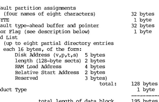
Next comes a data block, always in the following format: Default partition assignments
(four names of eight characters) IOBYTE
Default type-ahead buffer and pointer Honor Flag (see description below) Load List
(up to eight partial directory entries each 16 bytes, of the form:
Disk Address (v,p,t,s) length (128-byte sects) RAM Load Address
Relative Start Address ReservEd
product Type
5 bytes 2 bytes 4 bytes 2 bytes 3 bytes)
total:
total lergth of data block
32 bytes 1 byte 32 bytes
1 byte
128 bytes 1 byte 195 bytes
This data block is initialized by the Master before Boot phase 2 is sent out. A description of each field follows:
Default partition assignments:
These are the assignments specified in the User Configuration Table entry (created by USERS), if a BIOS is to be loaded. If a Log in Please or OS Menu is to be loaded, these fields are urrlefined •
IOBYTE:
This comes from the Machine Table entry for this machine. If there is no Machine Table entry, the IOBYTE will be 00 and the Boot Phase 2 program should attempt to determine the console
[image:7.621.108.438.242.455.2](Boot phase 2, continued)
Default type-ahead buffer:
As specified in the User Configuration Table (set up by USERS) , if the user name/password is found. Otherwise, undefined. Honor Flag:
This flag is set to show the extent to which the login request was honored, i.e. what sort of program will be loaded next. The lower nibble will be:
o -
An as exactly matching the request will be sent, i.e. its option Map will match the machine's (unless a high-TPA BIOS was requested.)I - A default as will be sent, of the general type as the requested one but with a different option map. Implies that there is no as available with the exact option con-figuration of the machine.
2 - A "login please" program will be sent. Implies that the name/psw were not found in the User Table.
3 - An "aS Menu" program will be sent. Implies that no OS of the requested type could be found that would stand a chance of running on the machine logging in. In the
initial release this will probably be a tough-luck message rather than a real menu.
4 - Total failure, no program will be loaded.
The high bit of the honor flag is used to show Whether the machine is in the Machine Table, viz.:
o -
Normal (the machine is in the Machine Table.)1 - Not found. without a Machine Table entry, Boot phase 2 will have to try to figure out the correct IOBYTE for
this machine, probably by examining the PROM.
Depending on the value of the Honor Flag, Boot Phase 2 may print a message (using PROM I/O routines) notifying the user of an unusual situation (e.g. a default as or a Machine Table lookup failure.) Load List:
This list consists of entries from the System Directory, with the eight-byte names removed, making each entry sixteen bytes long. Each entry describes a file to be read from the net, including information as to where it is to be loaded and where to begin executing it. If fewer than eight files are specified (actually two will be a more common number), the length field in the entry after the last one used is set to zero by the master (in fact, the block is filled with zeros on the end, but these might be legal values in other fields.)
Product Type:
Included in Boot phase 2 because Z80machines do not know their own product type and so must find out from the Master.
"LCX;IN PLEASE" program
This program will be loaded in lieu of an
as
if the name/psw in the login request do not match any entry in the User Table. (This will often be true on auto-login by serial number.) It first action will be to request an "instant logout" of the current user number. The program will then· ask the user for a name and pa.ssword. After appen-ding the binary serial number, product type and HiNet user number, the program will wait for a poll of the login pseudo-user (253), issue a login request, and prepare for the log-ack.The Master's response will be handled the same by this program as it would be in step 6 of the above boot procedure; i.e., the serial number
in the response will be matched against our own, and the login request will be retried if the serial numbers don't match.
If they do match, and the response is an ack, the program notes the new HiNet user number and waits for a new Boot phase 2 to be sent to that user number. It then executes Boot phase 2.
If the serial number matches but the response is a deny, there is a major bug. A diagnostic message will be sent to the screen.
"OS MENU" program
This program loads in lieu of an
os.
It uses PROM I/O facilities and has access to the infonnation passed in the Boot phase 2 code and to the HiNet user number.The program reads the
as
table from the master and presents to the user a menu of the OS's capable of running on the machine logging in.(Presenting the option map in a reasonable way may be difficult.) When the user selects one, the program loads it -- probably by re-initializing the still-resident Boot Phase 2 with the address of the selected
as,
and re-running Boot Phase 2.Since appearance of the "OS MENU" program impl ies that no systan of the type specified in the User Option Table could be found for the machine, it is unlikely that the default partitions will be suitable for the
as
eventually selected. Therefore the re-initialization of Boot Phase 2 must include new default partitions as specified by the user from the console. program must check that the requested partitions can be used under the requested OS. Any TPA utility version of this program will also have to ask for the default partitions, for the same reason. Note that this program is required to know the location of the OS table in the master.as
numberso
not to be used - can be returned if search fails, etc. 1 CP/M2 MS-DOS
3 unix
4 HOST
11 = CP/M 2
12
=
CP/M 8613
=
HiDOS14 through IF = other CP/M compatible OS's
21 = MS-DOS verse 2.0 22 = MS-DOS verse 2.x 23
=
MS-DOS verse 3.x24 through 2F = other MS-DOS compatible OS's
31 through 3F
=
unix-c~patible OS'sProduct Numbers
The Product Number specifies the general CPU board design without regard to peripherals. Therefore same Product Numbers refer to several models.
In some implementations the highest bit of the product Number same tables has been used to distinguish a serial versps parallel console, a role now handled entirely by the IObyte. Because of the previous usurping of this bit the number of Product Types is limited to 127, not 255.
o
Not to be used1
2 3 4 5 ,6
7 8 9 10 11 12 13
ZSBC-3 CPU's: OMS-3 OMS-3/A25 OMS-3/4004 OMS-3/4008 0MS-3/101 OMS-3/102 0MS-3/103 DMS-3/B DMS-3/F OMS-15 0MS-S080 OMS-4
DMS-1280 OMS-3/C OMS-5086
and HNS-86 OMS-5016 OMS-816 PC Adapter 0MS-16B OMS-808
"OSC-3" "Snart ADDS"
"FoX"
"OSC-4"
"Killer Bee"
Apricot Adapter Hex-29 Adapter OMS-200
Optional Device Drivers
This is a bit-map with the exception of the block describing the number of logical drives supported. This is pennissible because as of 9/13/83 we have done away with the logical ANDing of two bit maps, requiring instead an exact match with the Machine Table version. Since we have agreed to give England an arbitrary number of logical drives (up to 16), the only bit-mapped way of doing
it would use 16 bits or one-third of the bit map.
N.B. We are going to have to change the way we offer "custom" printer drivers since there is no way of knowing, a priori, whether a driver named "custom printer" will run on a given machine. bit device driver
o
8-inch floppies (SD and OMS DO) 1 5-inch Fox-floppies2 5-inch I~format floppies 3 8-inch HD with DMS controller 4 5-inch HD with Xebec controller 5 5 - i n c h HD with Adaptec controller 6 Port 0 type-ahead (console)
7 Port 0 polled ( " ) 8 Port 2 polled (printer) 9 Port 3 type-ahead (aux comm.) 10 Port 3 polled ( " " ) 11 Parallel Port 1 (console) 12 Parallel Port 1 (printer) 13 Parallel Port 2 (Fox printer)
14 Console/printer Mux (ADDS, 1280, 5000) 15 Spooler
16 Net Buffer (lk) 17 Real-Time Clock
18 Front-Panel Interrupt
19 Number of logical drives (bit 0) 20 Number of logical drives (bit 1) 21 Number of logical drives (bit 2) 22 Number of logical drives (bit 3)
--- Hard Disk Control Area Layout ---(Partition 0)
Logical Address
---track 0, sectors 01-lF track 0, sectors 20-28 track 0, sectors 29-38
track 0, sectors 39-78
track 0, sectors 79-80 track 1, sectors 01-08 track 1, sectors 09-14
track 1, sectors 15-16 track 1, sector 17 track 1, sector 18 track 1, sectors 19-20:
track 1, sectors 21-80:
(continued next page)
Contents
---Controller Program (unchang ed)
reserved for expansion of controller program HiNet User Name Table
Up to 128 16-byte entries:
8 bytes: user name or stn serial #
6 bytes: password 1 byte: OS code
1 byte: flags (incl big/small HiNet User Configuration Table
Up to 128 64-byte entries: 8 bytes: default A drive 8 bytes: default B drive 8 bytes: default C drive 8 bytes: default D drive 1 byte: length of typeahead 31 bytes: typeahead buffer Disk Allocation Table (unchanged) Bad Sector Table ( unchanged) Machine Table
Up to 128 12-byte entries: 4 bytes: Serial Number 1 byte: Product Number 6 bytes: Option Map 1 byte: IOBYTE write Mode Table
reservErl
Password Table product Type Table
up to 40 25-byte entries: 1 byte: Prod uct Type
request)
8 bytes: Boot phase 2 program name 8 bytes: Log in please program name 8 bytes: OS Menu program name
os
Tableup to 128 96-byte entries: 1 byte: OS number 16 bytes: Product Map
6 bytes: Option Map
--reserved--track 2, sectors 01-02 track 2, sectors 03-08 track 2, sectors 09-20
track 2, sectors 21-80
Cold Boot Loader (unchanged) reserved for use of Cold Boot Loader Systan Directory
Up to 128 24-byte entries: 8 bytes: File Name 5 bytes: Disk Address
2 bytes: Length (128-byte records) 4 bytes: Load Address
2 bytes: Execution Address Offset 1 byte: program/Data flag
2 bytes: -- reserved--