Bandwidth Enhancement of Circular Micro Strip Antenna
using Stub
Rajarshi Sanyal
Asst. Professor M.C.K.V.I.E Howrah, IndiaSekhar Rana
Asst. Professor M.C.K.V.I.E Howrah, IndiaS. Chakravorty
Associate Professor M.C.K.V.I.E Howrah, IndiaABSTRACT
A novel circular micro strip dual band stub loaded antenna is described. The antenna is built with a dielectric constant of (εr =2.33) with RT/5870 as the substrate material. Due to the effect of stub loading, dual frequency is produced at 1.88 GHz and 2.73 GHz respectively for the stub length=17 m.m.With the further increment of stub length, shifting of secondary resonant frequency is possible from 2.88 GHz to 1.99 GHz which further improves the percentage bandwidth using controllable dual band. The primary resonant frequency is fixed at 1.88GHz .Throughout the entire operation and the gain also remains constant.
Keywords
Circular patch, variable stub length, dual band response and Enhanced bandwidth.
1.
INTRODUCTION
In various wireless applications, micro strip antennas have been used to make the design more compact, reliable and light weight in nature. This helps in easier fabrication and integration of the same into the system [1].Unfortunately, the serious limitation of micro strip antenna is inherent narrow bandwidth [2].Most straight forward way of improvement of bandwidth by increasing substrate thickness with low dielectric [3]. Unfortunately the large inductive part of input impedance of antenna makes the surface wave generation which leads to low gain and low efficiency of antenna [4].The effective way of bandwidth enhancement is to load the surface patch either by narrow or wide slot [5]or by photonic band gap technique[6].The wide band antenna can be achieved by using the controllable frequency ratio of dual band system[7] The main aim of this paper is to present the controllable dual band with the help of single tunable stub [8] in circularly polarized (CP) antenna, which further increase bandwidth by overlapping of dual band.
2.
ANTENNA DESIGN
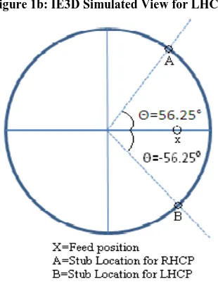
[image:1.595.341.515.135.709.2]Basic parameters of circular patch antenna are εr =2.33; h=1.6 m.m, tanδ =0.001 and radius of the circular patch =30 m.m is taken. Antenna is probe fed at (xf =9.5 m.m, yf = 0 m.m).The dimension and position of stub were approximated using on IE3D V.14Software. The width of stub is taken 1 m.m and the angular position of stub is taken either at 56.25° for right hand circular polarization (RHCP) or at -56.25° for left hand circular polarization (LHCP) from the center of the circular patch with respect to the axis of the feed position, as shown in fig.1 (a-c). This exhibits efficient radiation and optimum impedance matching. The length of the stub is varied from 17 m.m to 44 m.m to ensure the desired result.
[image:1.595.351.506.511.713.2]Figure 1a: IE3D Simulated View for RHCP
Figure 1b: IE3D Simulated View for LHCP
3.
RESULTS AND DISCUSSION
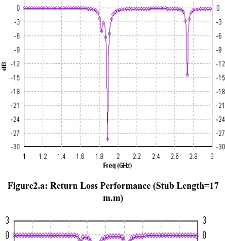
Simulation has been done by the method of moment based IE3D EM Design System (V: 14) simulator [9].Initially for the circular patch at feed point (Xf =9.5, Yf =0), resonance frequency was found to be 1.88 Ghz with bandwidth equal to 1.11% .Stub produces dual frequency response for the length of stub greater than half of the value of the patch radius. According to the simulation it is found that at l =17 m.m, the primary resonant frequency (f1) and Secondary resonant frequencies (f2) are 1.88 GHz and 2.73 GHz respectively as shown in fig2.a. It is observed that for the furtherincrement of stub length from17m.m to 30m.mhas resulted in a left shift of secondary resonance frequency towards the primary according to fig3. That is “f2 / f1” tends to unity w.r.t the increment of stub length as shown in table: 1. Also relevant VSWR<2 have been achieved for both the bands as shown fig4.
Figure2.a: Return Loss Performance (Stub Length=17 m.m)
[image:2.595.55.277.261.499.2]Figure2.b: Return Loss Performance (Stub Length=24 m.m)
Table 1: Summary of Proposed stub location
Figure3: Return Loss Performance (Stub Length=30 m.m)
At the optimum feed length 45 m.m, two separate frequency bands overlap which enhances the bandwidth to 2.55% with center frequency 1.90 GHZ as shown in fig5.Both LHCP and RHCP exhibit the same result. Fig6.a: shows the exponential Stub
Length (m.m)
‘f1’ (Ghz)
‘f2’ (Ghz)
Return Loss (db)
VSWR f1/f2
f1 f2 f1 f2
17 1.88 2.73 -28.81 -14.57 1.10 1.81 1.45 18 1.88 2.65 -28.56 -21.05 1.09 1.19 1.40
19 1.88 2.65 -28.86 -21.05 1.07 1.19 1.40 20 1.88 2.49 -28.28 -20.31 1.08 1.21 1.33
22 1.88 2.34 -27.6 -23.87 1.15 1.20 1.24
24 1.88 2.23 -26.81 -22.22 1.09 1.16 1.18
26 1.88 2.14 -25.95 -23.62 1.10 1.14 1.13
28 1.88 2.08 -25.11 -19.43 1.09 1.12 1.11
30 1.88 2.03 -24.29 -18.54 1.12 1.26 1.07
32 1.88 2.00 -23.52 -16.37 1.23 1.31 1.06
34 1.88 1.98 -22.81 -15.92 1.25 1.38 1.05
38 1.88 1.95 -21.32 -14.10 1.18 1.49 1.03
44 1.88 1.92 -21.10 -14.57 1.19 1.45 1.02
Figure4: VSWR for Stub Length=30 m.m
Figure5: Return Loss Performance (Stub Length=45 m.m)
Figure6.a: Variation of ‘f1’& ‘f2’ with Stub
Figure6.b: Comparison of Frequency Difference for different Stub locations
According to the Fig6.b: the different angular position is taken along with the proposed angular position, at θ = 30o
there is no secondary resonant frequency can be observed beyond the stub length =26m.m, at θ =45o both the frequency band maintain fair difference w.r.t the stub length =45 m.m. Hence there is no of overlapping between two bands.When the angular position of the stub is shifted by 180o with the proposed stub location i-e (θ= 56.25o+180o),it exhibit the reverse nature of the dual band separation w.r.t stub length increment.
3.1 Radiation pattern
2D Radiation pattern of proposed antenna as shown in Fig 7. (a-d) is in the broadside direction which shows the length effect on the difference between co-polar (φ=0°) and cross polar (φ=90°) pattern of ‘f1’ and ‘f2’.
Figure7.a: Radiation pattern at f1=1.88 GHz (Stub length=20m.m)
Figure7.b: Radiation pattern at f1=1.88 GHz (Stub length=45m.m)
Figure7.c: Radiation pattern at f2=2.49 GHz (Stub length=20m.m)
Figure7.d: Radiation pattern at f2=1.91 GHz (Stub length=45m.m)
4.
DIRECTIVE GAIN
Figure8: Peak Gain vs. frequency plot for Stub length=30 m.m
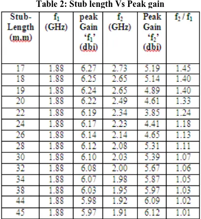
At the lower resonance frequency, the gain varies from 6.27 dbi to 5.97 dbi w.r.t increasing stub length whereas at higher frequency, which continuously shifts towards the lower, the gain varies from 3.85 dbi to 6.12 dbi as shown in table2. Fig 8 indicates that the peak value of the gain 6.1 dbi at 1.88 GHz and 5.39 at 2.03 GHz when f1 and f2 are separate at 30 m.m stub length. After overlapping at 45 m.m stub length the gain remain almost flat over 6 dbi (approx) from 1.88 GHz to 1.92 GHz. as shown in Fig9, which is the operating bandwidth.
Table 2: Stub length Vs Peak gain
5.
CONCLUSION
The simulation carried out on the new proposed stub loaded antenna configuration both for LHCP and RHCP have provided a useful design for a circular micro strip antenna with enhanced bandwidth using controllable dual frequency arrangement where the primary resonant frequency is fixed and the secondary resonance frequency shifts continuously towards the primary and finally overlapped with the same
6.
REFERENCES
[1] R.Garg,P.Bhatia,I.J.Bahl and A.Ittipiboon “Microstrip antenna design handbook”, Artech House: Newyork,2001.
[2] Griffin J.M. and Forest J.R.,’’Broadband Circuit disk Micro strip Antenna”, Electronics Letter, 18, PP 266-269, 1982.
[3] James,J.R. and P.S Hall, Handbook of Micro stripAntenna, PeterPeregrenus Ltd., London, 1989. [4] Kin-Lu Wong, ‘Compact and broadband microstrip
antennas’, John Wiley & Sons, New York, 2002. [5] C.K. Wu and K.L. Wong, ‘Broadband microstrip antenna
with directly coupled and gap coupled parasitic patches’, Microwave Opt. Technol. Lett., Vol. 22, pp. 348-349, Sept. 5, 1999.
[6] Microstrip and Printed Antennas: Recent Trends and Developments Debatosh Guha Dec. 2003.
[7] Deshmukh et.al.,”Multiband Configuration of stub- loaded slotted rectangular Microstrip Antenna”,IEEE Antennas and propagation Magazine, Vol, 52, No.1,2010.
[8] M. Du Plessis and J. H. Cloete, “Tuning stub for microstrip patch antenna,” in Proc. IEEE Antennas Propagat. Symp., June 1993, pp. 964–967.