http://dx.doi.org/10.4236/jis.2014.54018
An Efficient Trusted Computing Base for
MANET Security
Somya D. Mohanty
1, Vinay Thotakura
2, Mahalingam Ramkumar
31Social Science Research Center, Mississippi State University, Starkville, USA 2Microsoft, Seattle, USA
3Department of Computer Science and Engineering, Mississippi State University, Starkville, USA
Email: [email protected], [email protected], [email protected]
Received 28 July 2014; revised 25 August 2014; accepted 20 September 2014
Copyright © 2014 by authors and Scientific Research Publishing Inc.
This work is licensed under the Creative Commons Attribution International License (CC BY). http://creativecommons.org/licenses/by/4.0/
Abstract
Devices participating in mobile ad hoc networks (MANET) are expected to strictly adhere to a uni-form routing protocol to route data packets among themselves. Unfortunately, MANET devices, composed of untrustworthy software and hardware components, expose a large attack surface. This can be exploited by attackers to gain control over one or more devices, and wreak havoc on the MANET subnet. The approach presented in this paper to secure MANETs restricts the attack surface to a single module in MANET devices a trusted MANET module (TMM). TMMs are delibe-rately constrained to demand only modest memory and computational resources in the interest of further reducing the attack surface. The specific contribution of this paper is a precise characteri-zation of simple TMM functionality suitable for any distance vector based routing protocol, to realize the broad assurance that “any node that fails to abide by the routing protocol will not be able to participate in the MANET”.
Keywords
Algorithm/Protocol Design and Analysis, Network Protocols, Cryptographic Controls, Mobile Ad-Hoc Networks (MANET), Distance Vector (DV) Protocols, Authenticated Data Structures (ADS)
1. Introduction
A mobile ad hoc network (MANET) [1] is a dynamic subnet constituted of mobile computers (or devices) with limited wireless transmission range. MANET devices rely on each other for routing packets among themselves, and consequently, do not depend on a dedicated routing infrastructure.
MANET subnet to enable discovery of multi-hop paths for relaying data packets. Such rules govern processes like discovery of neighbors (devices within limited wireless transmission range), exchange of routing infor- mation between neighbors, maintaining a destination table (DT) and a neighbor table (NT) at every device, using information in the DT and NT to forward data packets, etc.
The rules that govern the actions of a MANET device are typically encoded as software executed by the device. Unintended functionality either deliberately hidden malicious functionality, or accidental bugs-in any component of a mobile device could potentially be exploited by attackers to 1) modify the functionality (routing software) of the device, or 2) modify the information stored by the device (in DT and NT), or 3) expose secrets of the device, thereby enabling the attacker to impersonate the device to advertise arbitrary “routing information”. Attackers could be legitimate owners of a device, or entities who may have exploited some hidden functionality in the device to acquire some extent of control over the device. Many such attackers may even collude together to wreak havoc on the ad hoc subnet.
A practical MANET device can come in several shapes and sizes, ranging from laptops to smart phones to special purpose sensors, constructed using a wide range of hardware/software components. It is obviously far from practical to rule out the presence of undesired functionality in every hardware and software component of every device that could take part in a MANET subnet, or malicious behavior/incompetence in every entity that has the ability to gain control of a device. It is, however, far more practical to assure the integrity of a single component in every device. For example, every MANET device could be required to possess a trustworthy chip/ module.
In the rest of this paper we shall refer to such a module/chip as a trusted MANET module (TMM). It is assumed that secrets protected by TMMs cannot be exposed, and the functionality of TMMs cannot be modified. All other software and hardware in every MANET device, and the user in control of the device (either through legitimate or illegitimate means), are assumed to be untrusted/hostile. The trust in TMMs, and more importantly, only the trust in TMMs, is leveraged to realize the assurance that “any device that does not strictly abide by the protocol will not be able to participate in the MANET”.
1.1. Trusted Computing Base for a MANET Device
For any computing system with a desired set of assurances, the trusted computing base (TCB) “is a small amount of software and hardware we need to rely on” [2] to realize the desired assurances. In other words, the desired assurances can be realized even if all other components of the system misbehave. From this perspective, TMMs can be seen as the TCB for MANET devices. As a specification of the TCB we provide a comprehensive functional description of TMMs.
In general, the lower the complexity of any hardware/software component, the lower the risk of unintended functionality. Towards this end, it is desirable that TMM functionality be deliberately constrained to demand low computational and memory resources to enable consummate verification, and thereby rule out hidden functionality in TMMs. Consequently, TMM functionality is restricted to simple sequences of cryptographic hash and logical operations, and to demand only a small constant memory size for their execution.
In the proposed approach the protocol specific rules to be followed by every MANET device are expressed as a simple algorithm f
( )
consisting of sequence of logical operations. The TMM functionality necessary to achieve the desired assurances can then be seen as functionality required to a) execute algorithm f( )
inside the TMM and b) TMM functionality necessary to assure the integrity of the dynamic inputs and outputs of( )
f . While the proposed approach has a broad range of applicability (where rules expressed by algorithm
( )
f will be different for different application scenarios) in this paper we restrict ourselves to MANET devices adhering to distance vector (DV) based routing protocols.
1.2. Organization
by the TMMs.
In the proposed approach the dynamic DT and NT are stored by the untrusted device as leaves of two index ordered merkle trees (IOMT). Only the roots of the two trees are tracked by the TMM. Section 4 outlines TMM functionality necessary to maintain an IOMT. Section 5 outlines the architecture of TMM and depicts how different elements of TCB functionality come together to provide the guarantee that devices will that do not strictly abide by protocol specific rules (for modifying NRS and DRs, and sending routing information and data packets consistent with the stored NRS and DRs), will not be able to take part in the MANET. Some relevant work in the area is discussed in Section 6.
2. Background
Any routing protocol can be seen as an extension of two basic routing strategies-distance vector (DV) or link-state (LS) approaches. In LS protocols information regarding a destination D is in the form of the state of all links of D (to neighbors of D). All nodes in the subnet possess the same information regarding D.
In DV protocols information regarding D is a destination record (DR) that indicates the hop count to D, and the next hop in the path to D. In general, every node possesses a different DR for destination D. Neighbors exchange DRs amongst themselves, and by comparing DRs for a destination D obtained from all neighbors, a node can determine its best DR for D, which is then stored in a table of DRs-the destination table (DT).
2.1. Distance Vector Protocols
A majority of popular MANET routing protocols are based on the DV approach in which every node maintains a destination table (DT) and a neighbor table (NT). The DT consists of a destination record (DR) for each possible destination. The NT consists of a neighbor record (NR) for each neighbor.
A DR
[
q x m n, , ,]
for a destination D (mobile device with address D) indicates a sequence numberq
, the time of expiryx
, hop-count m to the destination, and the next-hop neighborn
in the path to the destination. For an unreachable destination, the hop-count is ∞ (an integer constant larger than the maximum allowable hop-count). A “neighbor” of a device is another device to which the existence of a bidirectional path has been confirmed. Neighbors are expected to confirm each other’s continued presence, possibly by exchanging periodic HELLO messages. A neighbor who has has been silent for a long duration may no longer be considered a neighbor.In all DV protocols, a DR for destination D is initiated by D, indicating a fresh sequence number, hop count (to itself as)
m
=
0
, and time of expiryx
. The next hop is set to itself (orn
=
D
). This DR may then be advertised to all its neighbors. Neighbors of D store the DR in their respective tables after incrementing the hop-count field m to 1, and setting the next hop as D. The stored DR may then be advertised to their neighbors, and so on.In this fashion, any node in a connected subnet can acquire a DR for destination D: a device r hops from D will have a DR for D in it’s table, with hop count m=r. A device can receive a DR for a destination D from each of its neighbors. In general, the stored DR is replaced by the received DR if the received DR is fresher, or equally fresh and better.
Ultimately, the purpose of maintaining the DT and NT is to relay data packets. A device
S
which desires to relay a data packet to D can do so only if it has a usable DR for D. A DR[
q x m n, , , =R]
for a destination D is considered as usable only if m< ∞, the DR has not expired, and the next hop n=R continues to be a neighbor. The data packet may now be relayed to the next hop n=R. The device R at the next hop can likewise relay the data packet onwards to it’s next hop, indicated in a usable DR for D in its DT, and so on, until the data packet reaches D. When a device X receives a data packet intended for a destination D from a neighbor Y, and finds that it no longer has a usable DR for D, it responds by advertising a route error (RERR) packet. Y may now update it’s stored DR for D (by setting m= ∞) and relay the RERR to it’s upstream neighbor (who had earlier sent the data packet to Y), and so on.flooded in the subnet. Any node with a usable DR for D, (or D itself) may include the DR in a route response (RREP) packet which is relayed back to the source.
2.2. Covert and Overt Attacks
Broadly, an attack by a participating device (say, A) on a MANET can be seen as an attempt to send a routing/data packet P to a neighbor (say, B) where the contents of packet P were not generated in strict compliance with the protocol. Even more generally, an attack may also include the act of not sending a packet P (when the protocol calls for a packet to be sent).
An attack is successful if B is unable to distinguish between packets created strictly according to the protocol and packets created in violation of the protocol. If B is able to determine that a packet has been created by A in violation of the protocol, or that A should have sent a packet (when it did not), the attack is deemed unsuccessful (as B now has the ability to penalize A by no longer entertaining A as a neighbor).
Attacks that can be inflicted on a MANET subnet by a participating device can be broadly classified into overt and covert attacks. Overt attacks include incorrect packet formats, and illegal modifications to a relayed DR (for example, changing sequence number, expiry time, or changing hop count in any other way except incrementing by one, etc.). The reason that such attacks are overt is that 1) attacks like incorrect formats can be readily identified, and 2) if suitable cryptographic authentication strategies are used to protect the integrity of DRs advertised by devices, then the receiver of such a packet can readily detect illegal modifications and drop the offending packet.
The main challenges in the practical realization of assurances against overt attacks are two fold. The first stems from the overhead for cryptographic authentication schemes-especially for carrying over authentication over multiple hops. The second is that cryptographic strategies are (ultimately) at most only as strong as the mechanism used for protection of a device’s secrets. The absence of reliable mechanisms to protect secrets assigned to devices from attackers (who may even be the owner of a device) implies that attackers may even share secrets exposed from multiple devices to advertise misleading (but duly authenticated) “routing information” at will.
Unlike overt attacks, covert attacks may not be readily discernible by the receiver of a packet-even with sophisticated cryptographic authentication schemes. Examples of such attacks include 1) replaying DRs that were invalidated (or rendered sub-optimal) due to recent changes in topology; 2) rebroadcasting RREQs (instead of responding with an RREP) when a usable path exists; 3) not relaying data packets, or relaying data packets incorrectly (for example, to a device that is not the next hop in the best DR for the destination); 4) invoking unwarranted RERR packets (even when the link to the next hop is not broken); 5) accepting packets from (or relaying packets to) “neighbors” to whom a bidirectional link does not exist (thereby, making sure that the reverse path will fail), etc. 6) attacks based on misrepresentations of current time; for example, the clock of a device may be modified to make it think that a DR has expired.
The reason that such attacks may not be easily detectable is that in a scenario where a device C receives a packet from a device A, there is no tangible way for the routing process in a device
C
to confirm that A does have a link to it’s neighbor B (when A claims that the link is broken) or that A does have a better path (when A advertises a suboptimal path). While it might appear that a fairly sophisticated monitoring process in a neighbor ofC
, (say) Y, which had earlier sent the better path to A, may be capable of detectingA’s malicious intention it is entirely possible that Y’s advertisement was not received by A (for example, due to collision).
Furthermore, it is also possible for an attacker A to exploit collision-avoidance mechanisms used in wireless medium access protocols to send some information to it’s all neighbors while simultaneously ensuring that the information will not be heard by a specific neighbor B. For example, A can get to know of an impending reception by B from a CTS (clear to send) packet from B. By transmitting information at a time that overlaps with B’s reception, A can ensure that it’s suspicion-raising transmission will not be heard by B. An attacker A can also exploit this ability to carry out other possible attacks like 1) claiming it has lost it’s link to B to all its other neighbors (but continue to use B as a neighbor for it’s own purposes); 2) faking relay of a data packet or route error packet to the next hop, etc.
such attacks by either modifying the routing process, or hardware drivers, or modifying the contents of the DT/NT, or by modifying MANET parameters like τ, ,∞τs etc. Even a less sophisticated rogue process that does not have the ability to do so, may be able to modify the interpretation of the contents of a DT/NT by resetting the device’s clock.
3. Overview of TMM Based Approach
To our knowledge, the proposed approach is the first to address both overt and covert attacks, under the reasonable assumptions of 1) a secure pre-image resistant cryptographic hash function h
( )
exists; and 2) every MANET device possesses a TMM that is read-proof and write-proof.All TMMs are identical except that each have a unique identity, and possess unique secrets which enable any two TMMs to compute a pair-wise secret. Every TMM has a clock which ticks at (very close to) the same frequency. However, the clocks of TMMs are not synchronized. In this paper we shall assume that the identity of the TMM in a device A is also A. However, to distinguish between the device and it’s TMM, we shall refer to “device A” as A and “TMM A” as A.
It is assumed that all components of MANET devices and the user(s) in control of the device are untrusted/ hostile. In other words, the untrusted user/device is able to modify the routing software, and/or the device’s clock, and/or the DT/NT, and may possess complete control over the wireless interface. Not with standing such capabilities attributed to the rogue software/hardware in the device or the user controlling the device, the goal is to ensure that “all devices will indeed abide by the protocol rules”.
Any MANET packet sent by a device A to device B is accompanied by a corresponding message from TMM A to TMM B. Pairwise secrets between TMMs are used to compute message authentication codes (MAC) for assuring the integrity of such messages. As devices can not impersonate TMMs, device A is required to request it’s TMM A to create a message, and deliver the message to device B; device B is similarly expected to submit the message to it’s TMM B and receive an acknowledgement message that can be conveyed back to A through A.
The TMM approach to secure MANET routing can be seen as consisting of two broad steps: a) representation of protocol rules as a simple algorithm f
( )
that can be executed even inside the confines of severely resource limited TMMs, and b) ensuring the integrity of inputs and outputs of the algorithm;Towards the first step we outline an algorithm fdv
( )
suitable for any distance vector based protocol. The inputs to the fdv( )
are restricted to one DR for a destination, up to two NRs (corresponding to two neighbors), protocol specific constants, and parameters associated with an event.An event can be the a message received from another TMM, or a request from the device. The occurrence of an event may necessitate i) a modification to the DR (say, for destination D) and/or two NRs (say, for neighbors F and
G
) and ii) creation of up to 2 messages-one intended for neighbor F and one forG
. For each type of event (specified by event parameters) the algorithm fdv( )
specifies a) the manner in which a DR for D and up to two NRs for F andG
will need to be modified; and b) the type of messages to be created and sent to F andG
.Towards assuring the integrity of inputs/outputs of fdv
( )
it is required to 1a) assure the integrity of all dynamic DRs and NRs stored in the DT/ NT; 2) protect the integrity of the (static) constants, and 3) assure the integrity of messages exchanged between TMMs.3.1. Integrity of Inputs and Outputs
Resource limited TMMs can not store the entire DT and NT inside their protected boundary. TMMs maintain a succinct summary of the DT and NT in the form of two cryptographic hashes ξdt and ξnt respectively. More specifically, ξdt and ξnt are roots of two index ordered merkle trees (IOMT): root ξdt corresponding to the DT, with DRs as leaves of the tree, and root ξnt corresponding to the NT, with NRs as leaves.
Similar to the Merkle tree [5], the IOMT is a binary hash tree maintained by an untrusted prover to demonstrate the integrity of dynamic records (also maintained by the prover) to a resource limited verifier that stores only a single cryptographic hash-the root of the tree. For a database with
N
records, the prover stores allN
records, and in addition, 2N−1 cryptographic hashes, which are nodes of the binary tree, distributed over log2 N levels. The verifier stores only a single node-the root of the tree.number of dynamic records stored in an untrusted location (the untrusted device), even a plain merkle hash tree can be used. However, to address covert attacks, it is not sufficient for a TMM to be able to merely verify the integrity of a DR for a destination D or a neighbor record for a neighbor R; it is also essential for the TMM to be able to verify that an NR for R or a DR for D does not exist. If TMMs can not readily verify non-existence, the untrusted device will be able to hide a DR or NR that does exist, to perpetrate covert attacks. The use of IOMT instead of a plain merkle tree prevents such attacks.
The integrity of constants are assured by including a one-way function of the constants in the process of computing shared secrets between TMMs. Protocol specific constants are used in the process of initializing a TMM to operate in a specific MANET. All TMMs in a MANET will need to be initialized with the same constants, as TMMs initialized with different constants will not be able to agree on a shared secret. Such pairwise secrets are used for computing message authentication codes (MAC) for TMM messages to assure the integrity of messages in transit.
However, protecting the integrity of messages in transit is not sufficient. It is also necessary to have proactive strategies to guarantee that messages created by a TMM A for consumption of TMM B are actually delivered to TMM B . Note that in the path between the two TMMs A and B are two untrusted middle-men the devices
A
and B that house the TMMs, who can easily drop messages.This issue is addressed by employing “locks”. A lock is a special field
s
in the NR. When a TMM A sends a message to a TMM B it sets the locks
in the NR of B. The lock can be reset only if an acknow- ledgement is received from B. As TMM messages can not be impersonated the acknowledgement from B can be provided to A only if the message from A was actually delivered to B. If the lock is not reset, A will no longer consider B as a neighbor. It does not matter if the misbehaving device (that dropped the message) was A or B. Both A and B will stop regarding each other as neighbors, and thus, will not be able to exchange messages.3.2. Records and Messages
From the perspective of a TMM, a record is of the form bfr=
[
v v v v1, 2, 3, 4]
, and is associated with a record hash( )
( )
11
0 0
r
0
r
v h
h v
ω
= = = ≠ r (1) A destination record (DR) for a destination D is of the form rD =
[
qd,x m nd, d, d]
where the four values are the sequence number, time of expiry, hop count, and next hop. The DR[
q x m na, a, a, a]
for a destination A is created by TMM A. As the clocks of different TMMs are not synchronized, the time of expiry is in terms of the clock of the TMM of the device in which the DR is stored. A DR with sequence number 0 is interpreted as a empty record[
0, 0, 0, 0]
.The NR rF for a neighbor F specifies 3 values l o sf, f, f, 0 (time neighbor was last-heard-from, the offset of the neighbor’s clock, and lock s (the fourth value is always zero, and is ignored). Once again, all values of time are according to the clock of the TMM in the device storing the NR. An NR with first field l=0
is interpreted as an empty record.
TMMs exchange authenticated messages (authenticated using pairwise secrets) of three types-HLO messages, DR messages that convey a DR, or data messages that convey the hash of a data packet. All messages have a common format
[
R y t a D, r, ,r r, r,νr]
=
M (2)
where R is the identity of the sender (TMM that created the message), yr is the type of message (HLO, DR or DATA); tr is a time-stamp of the sender R, ar is an acknowledgement field, which is 0 for a spon- taneous message, and for an ACK, set to the time-stamp of the message that is acknowledged. The value Dr is the identify of a destination, and νr is a cryptographic hash.
In DR messages Dr is destination that created the DR conveyed by the message. In DATA messages Dr is the ultimate destination of the data packet whose hash is conveyed by the message. In HLO messages Dr =0.
3.3. TMM Functions
The functional components of TMM can be broadly classified into a) IOMT functions that enable the TMM to maintain two virtual databases-a DT and NT-by storing only the IOMT roots; b) mutual authentication functions; and c) protocol specific functionality expressed as an algorithm fdv
( )
executed inside TMMs.These functional components are accessed through interfaces exposed by the TMM. IOMT related functions
( )
mt
F , Fcat
( )
and Feq( )
that perform simple sequences of hash operations and issue various types of self-memoranda. A self-memoranda issued by a TMM to itself (for use at a later time) is authenticated using a secretχ
known only to the TMM.Function Finit
( )
is used to initialize a TMM to operate in a MANET. Function Fmsg( )
is used to notify the TMM of the occurrence of an “event”. An event can be receipt of a message from another TMM, or a request from the device (for example to send a DR, initiate a data packet, remove a stale DR/NR, etc); Fmsg( )
stores event (message) specific parameters like R, yr, tr, ar, Dr, νr and the event time t (time at which the occurrence of the event was notified) in a reserved event register E inside the TMM.Function Fupd
( )
which executes fdv( )
. Inputs to Fupd( )
include two DRs for D (a stored DR and a received DR) and two NRs (for F andG
). Depending on the nature of the event, execution of fdv( )
may result in the modification of up to the three records (a DR and two NRs). Accordingly, Fupd( )
updates the IOMT roots and creates messages dictated by two outputs Of and Og of algorithm fdv( )
.Inputs to Fupd
( )
also include self-memoranda which simultaneously enable the TMM to 1) verify the consistency of the DRs and NRs against the current IOMT roots, and 2) modify the roots in accordance with the changes to the DR/NRs resulting from execution of fdv( )
. Fupd( )
ensures that only DRs/NRs consistent with the current IOMT state can be provided as inputs and modified only as specified by the algorithm fdv( )
. On completion of Fupd( )
the device is expected modify the DR and two NRs in exactly the same manner. If not, the DR and the NRs will no longer be recognized as consistent with the IOMT roots stored inside the TMM (as inconsistent DRs cannot be advertised to other devices or used for forwarding data packets; and no messages will be accepted from/sent to neighbors with inconsistent NRs). The device is also expected send the messages to F andG
. If not, an acknowledgement from F can not be submitted to the TMM (as TMM messages can not be faked) to reset the locks
in the neighbor record of F, which will result in the loss of the link to F.3.4. Distance Vector Algorithm
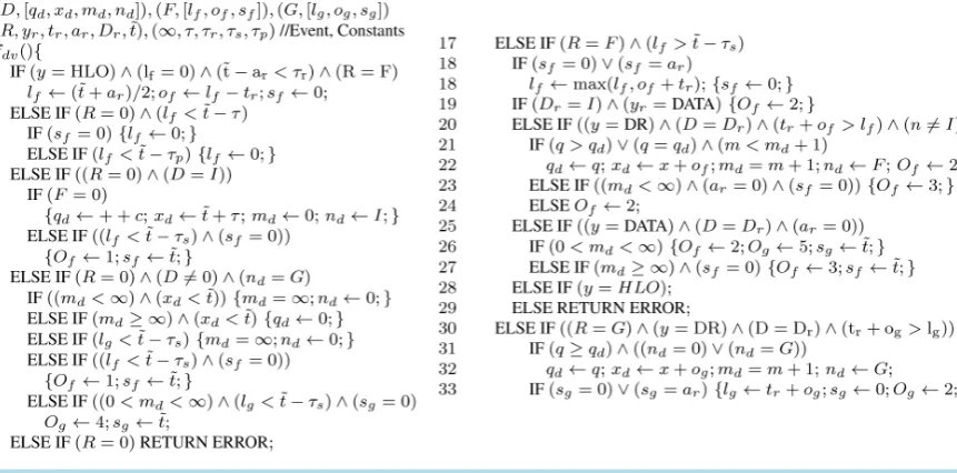
Protocol specific components of the TMM based approach include a specification of constants, and the algorithm fdv
( )
(Figure 1). The inputs to fdv( )
include a DR for D two NRs (F andG
), event related parameters, and constants ∞, ,τ τ τs, r and τp. IfD
=
0
the implication is that no DR has been provided as input (ifF
=
0
no NR for F is provided). qd =0 it signifies an empty DR. lf =0 implies an empty NR for F. D=I implies self-DR (as I is the TMM identity). Most often, the neighbor F is the source of a event (or F=R), and the neighborG
is the next hop nd in the DR for D (or G=nd) .In the algorithm in Figure 1 the events can be classified into three broad categories: 1) request from the device (
R
=
0
, lines 3 - 16); 2) message from F (or R=F, lines 1 - 2 and 17 - 29) and 3) message fromG
(R
=
G
, lines 30 - 33). Exection of fdv( )
may result in the modification of the DR/NRs and two outputs Of and Og which specify the nature of the message to be sent to F andG
respectively.The constant τr is the maximum permitted round trip time to recognize the existence of a neighbor. If 0
f
l = (empty record for F) and if the received message from F=R is an ack., such that t−ar<τr, a successful handshake has occurred (lines 1 - 2). The time tr according to the sender is roughly lf =
(
t+ar)
2in terms of the receivers clock. The clock offset of the sender is then of = −l tr. .
Adding a NR for F after a successful handshake causes the NR for F to change from
[
0, 0, 0]
→ l of, f, 0. Once a NR has been added, the neighbor is expected to periodically affirm it’s continued presence by sending messages (HLO messages if there is no reason the send other messages). On receipt of a message from F with a time stamp tf the last-heard-from field is updated to lf =tf +of.Figure 1. DV Algorithm.
acknowledgement, the inactive NR is retained for duration τpτ (lines 3 - 5). The reason for retaining a stale NR of F for some duration is to ensure that F can not be added back as a neighbor (after performing a handshake).
DR and DATA messages can be sent only to active neighbors, and only if the neighbor does not have the lock
s
set. A neighbor F is active at event time t if t−lf <τs. To send a DR message to F to send the DR for D a value Of is set to 1. To send the DR toG
the value Og is set to 1. When a DR or DATA message is sent to active neighbor F with sf =0, the lock sf is set to t. Later, when an ack. is received from F with ar=sf, the lock is reset.An acknowledgement for a DR/DATA message from F can be sent by setting Of =2 or Of =3. Specifically, Of =2 implies a simple acknowledgement (the only purpose of which is to reset the lock).
3 f
O = is a DR message that simultaneously acknowledges a received message and conveys a DR. Og =4 implies initiation of a DATA message to
G
; Og=5 implies relaying a DATA message to G.For example, when a DATA message is received from F to indicating Dr =D as the destination, if the DR for D is usable md < ∞, and the next hop nd =G is active, then a simple acknowledgement is sent to F (by setting Of =2); to forward the DATA message to G the value Og is set to 5. However, if no valid DR for D exists, the acknowledgement sent to F also conveys the bad DR for D
(
Of =3)
so that F can update it’s DR for D (as the DR has been invalidated). Similarly, when an invalid DR message is received for F and the stored DR is good, the good DR is sent along with the ack.Creating a new DR for itself implies incrementing the monotonic counter
c
and using it as the sequence number for the freshly created DR. The time of expiry is set to τ +t. Hop count is set to 0, and next hop is set to itself (line 7). The self DR can be sent to F if F is active (line 8).Lines 9 - 13 depicts events for which DR D needs to be updated on request by the device: setting height to
∞ in an expired DR (line 10); deleting an expired DR (line 11); setting hop count to ∞ as the next hop
d
n =G is inactive (line 12).
Lines 13 - 15 depicts events for sending a DR to an active neighbor F (line 13); initiate a data packet to D by creating a DATA message
(
Og =4)
to next hopG
in a valid DR (lines 14 - 15).Lines 17 - 29 correspond to events where a message has been received from active neighbor R=F. Update time stamp if no lock has been set, or if the message is an ack. that clears the lock
(
ar =sf)
(line 18); DATA message with the receiver I as the destination Dr; send ack to F(
Of =2)
(line 19). DR message (line 20 -DATA message (lines 25 to 27) from F with Dr =D which is not an ack
(
ar=0)
; relayed to the nexthop G (if a path exists to D) along with an ack to F (or Og =5,Of =2); if path does not exist DR message is sent to F as ack
(
Of =3)
.Lines 30 - 33 G is the source of a DR message. The DR is updated (lines 31-32) if fresher or equally fresh. The time stamp is updated and an ack created
(
Og=2)
. G can be the source of DR messages under threeconditions: 1) when no DR currently exists and the DR supplied by G makes G the next hop; 2) when G provides an update (which could be a shorter or longer path); or c) if in response to a DATA message sent to the next hop G, a DR message is received (route error).
4. Index Ordered Merkle Tree
A binary Merkle hash tree is constructed using a pre-image resistant hash function h
( )
(for example, SHA-1). A tree with N leaves has 2N−1 nodes distributed over L+1 levels, where L= log2N. At level 0 are N leaf-nodes: one corresponding to each leaf (a database record), typically derived by hashing the leaf. At level 1 are 12 2
N =N nodes, each computed by hashing together a pair of adjacent nodes in level 0. More generally, level
i
has N 2i nodes computed by hashing a corresponding pair of nodes in leveli
−
1
, and so on, till we have a lone node r at level L—the root of the binary tree.4.1. IOMT Leaves and Nodes
An IOMT is very similar to a merkle tree except for the imposition of a special structure for every leaf. The leaves of an IOMT take the form
(
A A, ′,ωA)
,=
L (3)
where A is the index of a record bound to the leaf,
A
′
is the next index, and ωA is the record-hash for a record corresponding to index A. Every leaf points to the leaf with the next higher index; the leaf with the highest index wraps around and points to the leaf with the lowest index. If ω =A 0 then the record bound toindex A is empty.
Corresponding to a leaf
(
A A, ′,ωA)
is a leaf node computed as vA=h A A(
, ′,ωA)
. A leaf bound to an empty record (third field zero) is a “place holder” for the index.Two sibling nodes
u
andv
in the same level of the binary tree are hashed together to compute their common parentp
as( )
, ifif 00( , ) if 0, 0
V
u v
p H u v v u
h u v u v
=
= = =
≠ ≠
(4)
At level
0
of an IOMT with N leaves are N leaf nodes-one for each leaf. Level 1 of the tree has2
N
nodes, level 2 has N 4 nodes, and so on. The lone node at level log2N is the root of the tree. Prover and Verifier: The prover stores all records, leaves, and nodes. The verifier stores only the root of the tree. For purposes of this paper, the prover is the untrusted device; records are DRs/NRs in the DT/NT maintained by the device. The verifier is the TMM in the device.
In the tree maintained by the prover, if a node r at level
a i
+
is an ancestor of a nodev
at levela
, the prover can readily can readily identify a set ofi
nodesv
, such thati
repeated applications of HV( )
starting withv
will result in r. Let us denote by r= f vm( )
,v , such a sequence of HV( )
operations. If thehash function is pre-image resistant it is guaranteed that (given r= fm
( )
v,v ), it is not feasible to determine′ ≠
v v or v≠v′ satisfying r= fm
(
v′,v)
or r= fm(
v,v′)
.Thus, if the root of the IOMT is r, and if the verifier (TMM) is provided values
v
required to verify that(
4, 7, 4)
v=h ω is a child of r (or r= fm
( )
v,v ), the TMM is convinced of the existence of record withrecord-hash ω4 for index 4. Simultaneously, the existence of a leaf
(
4, 7,ω4)
also conveys to the TMM, the non-existence of any leaf with index that falls between 4 and 7. Likewise, the existence of a leaf (say)(
7, 2,ω7)
(with a wrapped around pointer) indicates that no leaf exists for an index greater than 7, or less than 2.
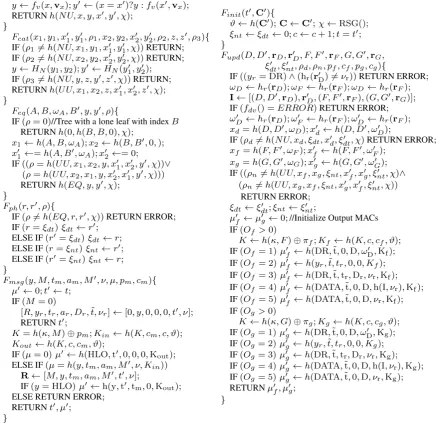
4.2. IOMT Functions
TMMs expose a function Fmt
( )
(Figure 2) that performs fm( )
operations verify the existence of a specific relationship—y= fm( )
x,v —between two nodes x and y. Having verified that x is a child of y in anIOMT, Fmt
( )
outputs a self-certificate (a memorandum to itself) to remind itself that “it has been verified by me that x is a child of y.” Such self-certificates are authenticated using a secret χ—a secret that is ran- domly generated every time a TMM is powered on/initialized.This secret is used to compute message authentication codes (MAC) for such self-memoranda. Three type of self-memoranda are issued by TMM functions.
(
)
(
)
(
)
1 2 1 2 , , , , , , , , , , , , , , , nu uu eq
h NU x y x y
h UU x x y x x y
h EQ r r
ρ χ ρ χ ρ χ ′ ′ ′ ′ = ′ = ′ = (5)
A function Fmt
( )
takes a nodex
, and a set of complementary nodesv
, and a value x′ (which may be the same asx
), and computes y= fm( )
x,v , and y′= fm(
x′,v)
to issue aNU
certificate binding x y x, , ′ and y′. Function Fcat( )
combines up to 3 NU certificates issued by Fmt( )
to issue a UU certificate.( )
eqF generates equivalence certificates for roots before and after insertion/deletion of a place holder. Function Fcat
( )
combines three NU certificates to issue a UU certificate. From certificates(
)
1 h NU x y x y, 1, 1, 1, 1,
ρ = ′ ′ χ and ρ2=h NU x y x y
(
, 2, 2, 2′ ′, 2,χ)
it follows that y=HN(
y y1, 2)
is a commonparent of leaf nodes x1 and x2 (and if x1→x1′ and x2 →x2′, then y→y′). From the third NU certificate ρ3=h NU y z y z
(
, , , ′ ′, ,χ)
, as z is an ancestor ofy
it is simultaneously an ancestor of x1 and2
x , and thus, if x1→x1′ and x2 →x2′ then z→z′.
( )
eq
F verifies equivalence relations that involve insertion or deletion of place-holders. Consider a scenario where an IOMT includes two leaves: a leaf for index A, viz.,
(
A B, ,ωA)
, and a place-holder for an index B, of the form(
B B, ′, 0)
. If the place holder for B is to be removed, then the leaf for index A should be modified to(
A B, ′,ωA)
, and the leaf(
B B, ′,ωB =0)
should be replaced with an empty leaf(
0, 0, 0)
. In other words, to delete the place holder, a tree with nodes x1=h A B(
, ,ωA)
and a node x2 =h B B(
, ′, 0)
should be replaced with x1′=h A B(
, ′,ωA)
and x2′ =0 (leaf-hash of an empty leaf is 0). Now, given a certificate(
, 1, 2, , 1, 2, ,)
h UU x x y x x yρ = ′ ′ ′ χ (or ρ =h UU x x y x x y
(
, 2, 1, , 2′ ′ ′, 1, ,χ)
) it can be inferred that changing a root from y→y′ is equivalent to removing a place-holder.If the input
ρ
is zero, this function assumes that one of the two equivalent roots is zero, and the other corresponds to a tree with a lone place-holder(
B B, , 0)
. As the root of a tree with a single leaf is the same as the leaf hash, in this case the other root is r′ =h B B(
, , 0)
.Note that if changing an IOMT root from y→y′ corresponds to deleting a place-holder, changing an IOMT root from y′ →y corresponds to inserting a place-holder. The TMM does not care if an equivalence certificate is being used to insert/delete a place holder, or care about the index that is deleted/inserted.
Two IOMT roots ξdt and ξnt are stored in internal registers of TMMs. Such roots can be modified due to different events using Fupd
( )
, by providing appropriate NU and UU certificates. The IOMT roots can also be changed to an equivalent root (for purposes of inserting/deleting place holders in either tree).Specifically, function Fph
( )
exposed by TMMs can be used to insert or delete place holders in the DR tree with root ξdt or NR tree with root ξnt.Form the perspective of TMMs a self-certificate satisfying ρ =h NU x
(
, ,ξdt, ,x′ ′ξ χdt,)
is proof thatx
isleaf node in the DR tree. Now, if there exists values (say) (A,A′,ωA) satisfying x=h A A
(
, ′,ωA)
, the TMM concludes that ωA is the hash of record rA in the DR tree. Similarly, a self certificate satisfying(
, ,f g nt, , , ,f g dt)
h NU x x x xρ= ξ ′ ′ ′ξ χ along with IOMT leaves
(
F F, ,ωF)
′ and
(
G G, ′,ω)
that are pre-images of xf and xg respectively, and records rF and rG that are pre-images of record hashes ωF and ωG respectively, can be provided as proof of existence of two NRs for neighbors F andG
in the NT.A DR is of the form
[
v1=q v, 2 =x v, 3 =m v, 4 =n]
and an NR if of the form[
v1=l v, 2 =0,v3 =s v, 4 =0]
5. TMM Architecture
TMMs are resource limited modules that have only modest computational and storage abilities. They perform only simple logical operations necessary to execute fdv
( )
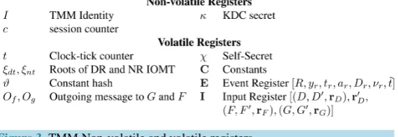
and hash operations required to maintain IOMTs, compute pairwise secrets, and MACs.Figure 3 depicts the internal registers of TMMs. Protected non-volatile registers are reserved for the TMM identity I, a secret
κ
issued by a trusted key distribution center (KDC), and a monotonic counterc
. The self-identity I is used for creating DRs for I . Every time a DR is created, or whenever a TMM is initialized, the monotonic counterc
is incremented. The secretκ
is used for computing pairwise secrets shared with other TMMs. [image:11.595.94.531.281.708.2]The volatile registers include the IOMT roots ξdt and ξnt. TMMs possess a volatile clock tick counter t which can be set to any value when a TMM is powered on/initialized, and thereafter, incremented at the same rate in all TMMs.
χ
is the self-secret generated whenever a TMM is initialized (which is used for self-MACs). Contents of the event register E, and input register I and constants C are used by algorithm fdv( )
to modify records in the input register, and set values Of and Og.Figure 3. TMM Non-volatile and volatile registers.
A function Finit
( )
initializes a TMM and sets the contents of a registers C andϑ
, sets the clock to a value provided by the device, initializes the roots of the NT and DT to zero, increments the monotonic counterc
, and generates a new self-secretχ
using a random sequence generator RSG().5.1. Mutual Authentication
Several low complexity key distribution schemes exist to facilitate computation of pairwise keys between two entities. The Modified Leighton Micali Scheme (MLS) [6] is well suited for dynamic networks with a soft limit on the maximum network size. In MLS scheme every node needs to store a single secret, and a pairwise public value corresponding to every node that was inducted earlier into the network. At a time a network has grown to (say) a million entities, the worst case storage requirement is for the last entity inducted into the network, which will need to store a secret and 999,999 public values. The 1000th entity will need to store only 999 public values.
Even if each public value is 16 bytes long, the worst case storage for a network that is expected to support up to 10 million entities is only 160 MB. In practice, as storage-especially unprotected storage-is indeed an inexpensive resource, even for mobile devices. Thus MLS, which requires only a single hash operation to compute a pairwise secret is especially well suited for computing pairwise secret between TMMs. The TMM needs to store only a single secret. The public values can be acquired (from the network operator) and stored by the untrusted device.
The secret κx is used by TMM X to compute shared secrets with other TMMs. Specifically, any two
TMMs X and Y can using their respective KDC secrets κx and κy to compute a common secret
(
,)
(
,)
xy x xy y yx
K =h κ Y ⊕π =h κ X ⊕π (6)
where πxy and πyx are pairwise public values made available to the untrusted devices that house TMM X and Y respectively. If MLS is used to compute the pairwise secret Kxy only one of the two nodes (X or
Y ) requires access to a public value; the other node employs the public value of 0 (if π ≠xy 0, then π =yx 0; if 0
xy
π = then π ≠yx 0).
The MAC secret shared between two TMMs X and Y is a function of Kxy, the respective monotonic counter values cx and cy, and a value
ϑ
used to initialize all TMMs taking part in the same application (for example, TMMs in all devices taking part in the same MANET). The valueϑ
is a one-way function of protocol-specific constants.The MAC secret Kout used by TMM X for computing MACs for outgoing messages to TMM Y, and the MAC secret Kin used by TMM X for verifying MACs for messages from Y are computed as
(
, , ,)
,(
, , ,)
,out xy x y in xy y x
K =h K c c ϑ K =h K c c ϑ (7)
If the MAC secret employed for a message is K , the MAC for the message created by X , viz.,
[
X y t a D, , , , x,ν]
is computed as(
, , , x, ,)
.h y t a D K
µ= ν (8)
Receiving Messages: TMMs accept messages from other TMMs, or request from the device, and store contents of the message/request in the event register
[
R y t a D, r, ,r r, r,νr,t]
=
E (9)
Note that apart from the contents of the message, the time at which the message was submitted is also recorded in the field t as the “event time.”
A function Fmsg
( )
accepts messages from a neighbor M , verifies the MAC and stores the message contents in register R. In addition, Fmsg( )
can also be used to create HLO messages—either on request by the device, or as an acknowledgement for a received HLO message. If Fmsg( )
is invoked with message source0
M
=
this is construed as a request from the device that conveys a type of requesty
and a valueν
. If( )
msg
F is invoked with input MAC
µ
set to zero, this is interpreted as a request to create a HLO message for a neighbor M . Else, the contents M t,m,am,M′,ν of the message are verified to be consistent with the MACµ
. If consistent the message register R is populated. In addition, if the message is of type HLO, then a MAC for an acknowledgement message with time stamp t is created.5.2. Updating TMM State Using
F
upd( )
Function Fmsg
( )
is invoked to notify the TMM of the occurrence of an event-either a message received from another TMM, or a request from the device, and populate event register E in the TMM. Processing the event involves execution of fdv( )
, which requires access to a currently stored DR for a destination D, a received DR for D consistent with νr (if the event is a DR message), currently stored NRs for up to two neighbors F andG
, and protocol specific constants. After processing the event, the end result is a change in the TMM state, and creation of up to two message (one for F and one forG
).As the response to the event may require modification of 3 records, the TMM will expect a NU certificate that simultaneously certifies the integrity of the current state (before the event) and future state (after processing the event) of a DR for D, and a UU certificate that simultaneously certifies the integrity of the current state (before the event) and future state (after processing the event) of two NRs (F and
G
). Specifically, the NU certificate instructs the TMM as to how the IOMT root ξdt should be changed due to the change to the DR rD; the UU certificate instructs the TMM as to how the IOMT root ξnt should be changed due to the change to the NRs rF and rG.The register I is used to store other inputs necessary to process an event by executing fdv
( )
. Specifically, the inputs include 1) a leaf from the DT IOMT for a destination D, except that instead of the third value ωD, the pre-image rD is provided as input; 2) a record rD′ consistent with value νr in the received DR message; and 3) two IOMT leaves (F andG
) from the NT tree; once again, instead of the valueω
, the pre-images are provided;The contents of the input register are provided as inputs to a function Fupd
( )
which makes the appropriate changes to records rD,rF and rG, accordingly modifies TMM state, and outputs MACs for messages. Apart from contents of the input register, other inputs to Fupd( )
are a ) the next states ξ ′dt and ξ ′dt; and b) aNU
certificate ρd and a UU certificate ρn.Function Fupd
( )
verifies that if the message is of type DR, then the record rD′ is consistent with νr and notes down the current record hashes ω ωD, F and ωG of the three records provided as inputs, and copies the contents of the leaves to the input register I.The protocol specific function fdv
( )
performs necessary modifications to the records. fdv( )
expects specific pre-conditions to be satisfied, failing which fdv( )
return error and terminates Fupd( )
. On successful execution of fdv( )
the DR and two NRs may be modified. In addition, fdv( )
instructs the types of messages to be sent to F andG
by setting values Of and Og.Till this point Fupd
( )
had simply assumed that the leaves for D,F andG
provided as inputs were consistent with the current IOMT roots. The four values ξ ρdt′, d and ξ ′nt and ρn simultaneously permits the TMM to verify this assumption, and modify the IOMT roots in accordance with the changes made to the DR and two NRs.By providing contents of a leaf in the DT and two leaves in the NT, the device claims that such such leaves are consistent with the IOMT roots ξdt and ξnt respectively. Let ω =D hr
( )
rD , ω =F hr( )
rF , and( )
G hr Gmodification of the record in response to the event) then the certificate ρd should satisfy
(
, , , , ,)
d h NU x dt x dt
ρ = ξ ′ ′ξ χ . Similarly, if the leaf hashes corresponding to F and
G
are xf and xg before the event, and x′f and xg′ after the event, the certificate ρn should satisfy(
, , , , , , ,)
d h UU xf xg nt xf xg nt
ρ = ξ ′ ′ ′ξ χ or ρd =h UU x x
(
, g, f,ξnt,x x′ ′ ′g, f,ξ χnt,)
.If the preconditions (before execution of fdv
( )
) and post conditions (after execution) are consistent with the current state(
ξ ξdt, nt)
and the next state(
ξ ξdt′, nt′)
the IOMT roots are modified to ξ ξdt′, nt′ .Finally, output messages are created depending on the values Of and Og. Inputs pf and cf (pg and
g
c ) to Fupd
( )
are necessary for computing the MAC secret to be used for the message to F (G
). Recall that O=1, 4, 5 are spontaneous (not ACK) messages: O=1 instructs creation of a DR message. O=4 instructs creation of a DATA message to initiate a data packet to D. O=5 instructs creation of a DATA message to relay a received DATA message to the next hop. O=2, 3 are acknowledgments; O=2 is a simple acknow- ledgement; O=3 is a DR message that simultaneously acknowledges a received DR/DATA message and conveys a DR.5.3. Deploying TMM Based MANETs
For MANET secured using TMMs every device has a TMM. A (perhaps off-line) administrator/operator of the MANET specifies the constants to be used. The off-line administrator is also responsible for ensuring that every device has access to public values necessary to facilitate computation of pairwise secrets between TMMs in devices.
To operate in a MANET the device is required to initialize it’s TMM. At this point the device has no records, and the IOMT roots are zero. From this point onwards the device has to maintain it’s DT/NT and the corresponding IOMTs to be in sync with the roots stored inside the TMM. Any number of place holders can be added in either tree by using certificate generation functions to create equivalence certificates and using Fph
( )
to modify the IOMT roots accordingly.As soon as a TMM is initialized the device can use Fmsg
( )
to perform handshakes with TMMs in neighbors, and then invoke Fupd( )
to insert neighbor records. Once a TMM recognizes neighbors, the TMMs own DRs can be incremented, and sent to active neighbors. Whenever a message is received from a neighbor the device submits the message to it’s TMM using Fmsg( )
and invokes Fupd( )
to modify the TMM state/create messages. Before Fupd( )
is invoked, as the device is aware of the precise changes that should be made to a DR and two NRs, the device can use IOMT functions to generate the necessary NU and UU certificates.The broad assurance that all devices taking part in a MANET will modify DRs and NRs in exactly the same manner as dictated by the protocol (algorithm fdv
( )
) is enforced as follows:1) Only TMMs initialized with the same set of protocol-specific constants will agree on a pairwise secret. This feature is used to assure the integrity of protocol-specific constants.
2) IOMTs are used to ensure that only DRs/NRs consistent with the IOMT roots stored inside the TMM will be considered as valid;
3) As the function fdv
( )
can not be modified, the DR/NRs consistent with the current IOMT roots can be modified only according to the algorithm fdv( )
.4) After modification of the records the device is forced to modify it’s copy of the records in the same way. 5) If messages mandated by fdv
( )
are not delivered by the device, the device can not retain the intended recipients of such messages as neighbors.6. Related Work and Conclusions
Devices taking part in MANET offer an enormous attack surface that can be exploited by attackers. Specifically, hidden malicious functionality in component of the MANET device could be exploited to illegally modify 1) the MANET software, or 2) the DT/NT or the device’s clock, or expose secrets protected by the device to advertise arbitrary routing information, and/or construct clone devices with arbitrary functionality. Current efforts to secure MANETs simply ignore a wide range of attacks stemming from such issues. In the proposed approach to secure MANETs all such attacks are side stepped as no component of the device is trusted in the first place.
[12].
In [7], the wireless transceiver is assumed to be inside a trusted boundary; in [8] the wireless driver is executed inside a trusted boundary. In [9], nuglets of currency are maintained inside the trusted boundary; they are incremented/decremented based on selfish/selfless acts performed by the device. However, [9] does not address specific mechanisms that will enable a trusted module to unambiguously infer that the associated device has indeed performed a selfish/selfless task.
Gaines et al. [11] argued that mechanisms to guarantee integrity of MANET require resource limited trusted modules to be able to vouch for the integrity of destination table and neighbor table stored by the device. They also recognized the need for the trusted module to identify non existence of routing information. For this purpose, [11] suggested the use of Bloom filters to store succinct summaries of routing records.
In [12] the authors employed an index order merkle tree (IOMT) for keeping track of routing records. The specific improvements in this paper compared to [12] are extending assurance to relay of data packets, and locking mechanism to ensure that messages are not dropped by untrusted middle-men. The proposed approach can be easily extended to other routing protocols by specifying an alternate set of rules in place of fdv
( )
. Our ongoing research efforts are directed towards identifying such rules for other routing protocols, and even applications that are totally unrelated to routing.References
[1] Royer, E.M. and Toh, C.K. (1999) A Review of Current Routing Protocols for Ad-Hoc Mobile Wireless Networks. IEEE Personal Communications, 6, 46-55. http://dx.doi.org/10.1109/98.760423
[2] Lampson, B., Abadi, M., Burrows, M. and Wobber, E. (1992) Authentication in Distributed Systems: Theory and Prac-tice. ACM Transactions on Computer Systems, 10, 265-310. http://dx.doi.org/10.1145/138873.138874
[3] Perkins, C.E. and Bhagwat, P. (1994) Highly Dynamic Destination-Sequenced Distance-Vector Routing (dsdv) for Mobile Computers. Proceedings of the Conference on Communications Architectures, Protocols and Applications,
SIGCOMM ‘94, New York, 234-244.
[4] Perkins, C. and Royer, E. (1999) Ad-Hoc on-Demand Distance Vector Routing. Proceedings of the Second IEEE Workshop onMobile Computing Systems and Applications, WMCSA ’99,90-100.
[5] Merkle, R.C. (1980) Protocols for Public Key Cryptosystems. IEEE Symposium onSecurity and Privacy,122.
[6] Ramkumar, M. (2008) On the Scalability of a “Non-Scalable” Key Distribution Scheme. IEEE SPAWN, Newport Beach.
[7] Song, J.-H., Wong, V., Leung, V. and Kawamoto, Y. (2003) Secure Routing with Tamper Resistant Module for Mobile Ad Hoc Networks. ACM SIGMOBILE Mobile Computing and Communications Review, 7, 48-49.
http://dx.doi.org/10.1145/961268.961286
[8] Jarrett, M. and Ward, P. (2006) Trusted Computing for Protecting Ad-Hoc Routing. Proceedings of the 4th Annual Communication Networks and Services Research Conference, CNSR ‘06, Washington DC, 61-68.
[9] Hubaux, J.-P., Buttyán, L. and Capkun, S. (2001) The Quest for Security in Mobile Ad Hoc Networks. Proceedings of the 2nd ACM International Symposium on Mobile Ad Hoc Networking & Computing, MobiHoc ‘01, New York, 146-155.
[10] Bloom, B.H. (1970) Space/Time Trade-Offs in Hash Coding with Allowable Errors. Communications of the ACM, 13, 422-426. http://dx.doi.org/10.1145/362686.362692
[11] Gaines, B. and Ramkumar, M. (2008) A Framework for Dual-Agent Manet Routing Protocols. IEEE GLOBECOM 2008 Global Telecommunications Conference, 1-6.