5
IX
September 2017
Static and Dynamic Analysis of Propeller Blade of
Aero Engine
Siddesha.K.M 1, Deepak.S.A.2, Dr.S.B.Kandagal3
1
PG Student, 2Asst. Professor, Dept. of Mechanical Engineering, AMCEC, Bengaluru 3
Principal Research Scientist, Dept. of Aerospace Engineering, IISc, Bengaluru
Abstract: Turboprop engines are the class of engines that drives the aircraft propeller. Turboprop consists of propeller, compressor, combustion chambers, turbine, and a nozzle. It operates with less speed, less cost, better fuel efficiency, low climbing speed, less greenhouse gas emission and less vibration. The propeller blade and shaft are considered to be the critical parts of a turboprop engine as they rotate at high speeds.
NACA4412 airfoil shape has been considered for the analysis. The 3D CAD model has been developed by using CREO tool and ANSYS WB is used for the FEA analysis.
The forces acting on the blade like aerodynamic forces, centrifugal force, lift force and drag force, acting on the propeller blades and shaft is estimated by strength of materials approach. These values are used as input forces in finite element analysis for static and dynamic analysis. The static analysis has been carried out to find max stress and max deformation location. Modal analysis has been performed to find the natural frequencies. The different forces acting on the blades like aerodynamic forces, lift force, drag force and centrifugal force have been calculated. Only 10% of the static forces have been considered as the dynamic varying forces for the harmonic response analysis.
The results obtained from analysis of propeller blade made of Ti-6Al-4V and FRP carbon materials reveals that propeller blade made of FRP carbon material is having less stresses and deformation.
Keywords: NACA4412, Airfoil shape, Natural frequency, Modal analysis, Harmonic response, Aerodynamic forces
I. INTRODUCTION
Aircraft engines are the major part of the propulsion system in an aircraft and it will generate the mechanical power. They are majorly classified into three types. They are turbine engines, piston engines and electric motors. Most of the aircraft engines using today is open rotors/turbofans. These engines will be suitable for long routes and fuel efficiency of these engines is less compare to turboprop engines. Turboprop engines are the types of aircraft engines which drives the propeller. Propeller blade is an important part of the engine.
[image:2.612.190.439.561.710.2]Propeller blade will have the airfoil shape which will be rotating at high speed. As the blade will be rotating it will push the air. If the airfoil is of the asymmetric shape, there will be pressure difference across the cross section. There will be lift and drag force acting on the surface because of the pressure difference, Along with these forces there will be aerodynamic thrust force acting due to air mass flow and centrifugal force casing due to rotation. For the design of the blade we need to consider all the above said forces and also need to find the natural frequency of the blade in order to avoid the resonance phenomena.
II. FEAANALYSISOFBLADE
Finite Element Analysis (FEA) is a numerical technique to solve the complex problems. There are so many commercial tools available for the FEA. Here we are using the ANSYS workbench for analysis purpose.
A. CFD analysis.
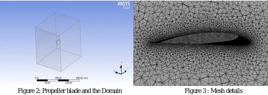
[image:3.612.98.527.219.371.2]NACA4412 airfoil coordinated are created from the www.airfoiltools.com and CREO tools is used create 3D CAD geometry CFD analysis is performed to find the lift and drag coefficient of the NACA4412 airfoil profile. ANSYS FLUENT module is for the CFD analysis. Below picture shows the CFD analysis steps and results.
Figure 2 shows the propeller blade geometry and domain shape used in the CFD analysis and Figure 3 shows the mesh details. Mesh size of 5mm for domain and 2mm for profile section is used.
Figure 2: Propeller blade and the Domain Figure 3 : Mesh details
[image:3.612.96.534.436.586.2]The CFD analysis has been carried out with 50 numbers of iterations. The Lift force and Drag force acting on the blade surface has been estimated at each iteration and corresponding Lift and drag coefficient are calculated. After 50 iterations the values are converged. Hence the value at 50th iteration is considered as the final value.The values of lift and drag coefficients versus number of iterations are plotted as below.
Figure 4 : Coefficient of Lift Figure 5 : Coefficient of drag
The lift and drag coefficients values obtained from CFD analysis are 1.46 and -1.14 respectively.
B. Static structural analysis
By using the CL and CD values Lift force and drag forces have been calculated. By using velocity triangle method velocity of discharge and mass flow rate is calculated and then aerodynamic thrust force is calculated. Centrifugal force also calculated by using the standard formula. The calculated forces are as below.
1) Aerodynamic Forces: T = 79.41 KN 2) Centrifugal Force:
4) Drag Force: FD = -44.86 KN
Static structural analysis is carried out by applying the above calculated forces to find the max stress and deflection of propeller blade. The results are as shown below.
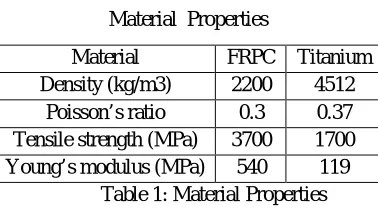
We have considered the FRPC and Titanium Material and analysis carried out by assuming FRPC as isotropic.
Material Properties
Material FRPC Titanium Density (kg/m3) 2200 4512
[image:4.612.212.401.132.237.2]Poisson’s ratio 0.3 0.37 Tensile strength (MPa) 3700 1700 Young’s modulus (MPa) 540 119
Table 1: Material Properties
C. Von-Mises Stress
Maximum von-Mises stress is as shown below and is located near the fixed end
Figure 6: FRPC - Max-873.43MPa Figure 7: Titanium - Max-1837MPa
D. Maximum deformation
[image:4.612.89.522.273.426.2]Maximum deformation is found at the free end and minimum at the fixed end.
Figure 8: FRPC - Max-2.8mm Figure 9: Titanium – 26.33mm
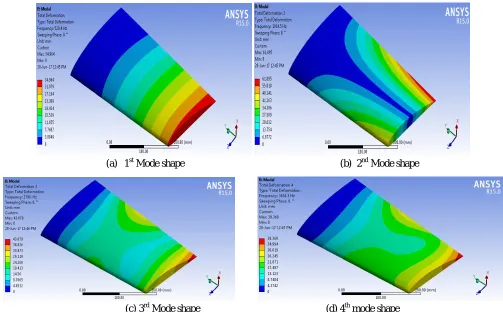
E. Modal Analysis
[image:4.612.88.525.475.660.2](a) 1st Mode shape (b) 2nd Mode shape
(c) 3rd Mode shape (d) 4th mode shape
The natural frequencies for FRPC and Titanium materials are tabulated as below
Mode Frequency (Hz)
FRPC Ti-6Al-4V
1 520.4 171.3
2 1914.5 610.28
3 2790 909.35
4 3616.3 1173.5
5 5670.4 1813
[image:5.612.53.556.75.387.2]6 7333.2 2357.3
Table 1 : Natural Frequencies
F. Harmonic Response Analysis
Harmonic analysis will be carried out to check the response of the system under dynamic loading conditions.
The dynamic forces considered as 10% of the aerodynamic forces, as there will be small variation in the unsteady flow. 1) Response (Stress)
(a) FRPC (b) Titanium
2)
Response (Velocity)(a) FRPC (b) Titanium
Figure 12: Velocity response
3)
Response (Deformation)(a) FRPC (b) Titanium
Figure 13: Deformation response
III. CONCLUSIONS
After verifying the results, it is found that the FRPC material is possessing low stress and deformation and also mode shapes. The further analysis can be carried out with some more composites like Kevlar/epoxy combination or tailor made composites with which we can get the desired properties.
REFERENCES
[1] Karna S. Patel, Saumil B. Patel, Utsav B. Patel, Prof. Ankit P. Ahuja, UVPCE, Ganpat University(www.uvpce.ac.in), “CFD Analysis of an Aerofoil”
International Journal of Engineering Research ISSN:2319-6890)(online),2347-5013(print), Volume No.3, Issue No.3, pp : 154-158 01 March 2014
[2] Mayurkumar kevadiya, Hemish A. Vaidya, “2D ANALYSIS OF NACA 4412 AIRFOIL”, International Journal of Innovative Research in Science, Engineering
and Technology, Vol. 2, Issue 5, May 2013
[3] Theju V1, Uday P S, PLV Gopinath Reddy, C.J.Manjunath , “Design and Analysis of Gas Turbine Blade”,, International Journal of Innovative Research in
Science, Engineering and Technology (An ISO 3297: 2007 Certified Organization), Vol. 3, Issue 6, June 2014
[4] Junjie Zhou, Bo Liu, Dingbiao Wang, Xiaoqian li “Dynamic Characteristics Analysis of Blade of Fan Based on Ansys “,Power and Energy Engineering
Conference 2010 .
[5] Ali Zare, Kannan M. Munisamy, Ali Najafzadeh, Behzad Shahizare, Ahmad Ahmadi and Ahmed Ali Jaafari, “Finite Element Analysis of Axial Fan Blade with
![Figure 1 : Basic nomenclature of an airfoil [1]](https://thumb-us.123doks.com/thumbv2/123dok_us/8305858.856034/2.612.190.439.561.710/figure-basic-nomenclature-airfoil.webp)