www.ijraset.com
Vol. 2 IssueIX, September 2014
ISSN: 2321-9653
I N T E R NA T I ON A L J OU R N A L F OR R E S E A R C H IN A P PL I E D S C I ENC E AND
E N G I N E E R I N G T E C H N OL O GY (I JR A S E T)
Review paper of enhance the efficiency of the
network by enhancing the error recovery by
using the backup path in MPLS network
Nisha
1,Bhavya singla
2,Taruna Sikka
31,2,3
Nisha, P.hd. scholar (ECE), Suresh Gyan Vihar University, Jagatpura-India
Abstract-:When data is transmitted at high speed through a cabled network, from any noise over the network or channel interference is introduce which causes heavy data loss. When data is transferring through a topology like bus or ring the chance of packet loss is much greater than in comparison of same ratio. In this present the discussion is being performed on high speed MPLS Ring network through which packet will be transmitted. As some fault occurs over the network in transmission of data which produces heavy data loss. In this method from which data can be transmitted a new hardware is introduce called save points. Save points are placed at equal distance between two nodes which maintain two paths for consistent data transmission. One path is the actual data path and other is backup path. As the signal noise is detected, it will inform the nearest save point and the save point will direct the communication to the backup path.
Keywords: Optical Fiber, MPLS, security, Save Point, Recovery.
1. INTRODUCTION OF COMMUNICATION
SYSTEM
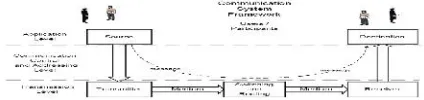
For transmission of data from one place to another place different modulation technology is used. Basic block diagram is shown in fig. 1 which is given below. Or Communication is
defined as “The activity of conveying Information such as
(voice, data, pictures or graphs and video) which is originated at one place (source) and sent to another place (destination), that is
some distance away from the source”
[image:2.612.43.255.602.652.2]In this diagram original signal is generated through the microphone and this signal is transmitted after modulate through channel and at the side of receiver original signal is regenerated after demodulation.
Fig. 1 Basic Communication System
2. OPTICAL FIBER COMMUNICATION
An optical communication system consists of a transmitter, which encodes a message into an optical signal, a channel, which carries the signal to its destination, and a receiver, which reproduces the message from the received optical signal. An optical fiber is a flexible, transparent fiber made of very pure glass (silica) not much bigger than a human hair that acts as a waveguide, or "light pipe", to transmit light between the two ends of the fiber. The field of applied science and engineering concerned with the design and application of optical fibers is known as fiber optics. Optical fibers are widely used in fiber-optic communications, which permits transmission over longer distances and at higher bandwidths (data rates) than other forms of communication. Optical fiber typically consists of a transparent core surrounded by a transparent cladding material with a lower index of refraction. Light is kept in the core by total internal reflection. This causes the fiber to act as a waveguide. Fibers that support many propagation paths or transverse modes are called multi-mode fibers (MMF), while those that only support a single mode are called single-mode
Fig 2 Optical Fiber Communication
3. OPTICAL TOPOLOGIES
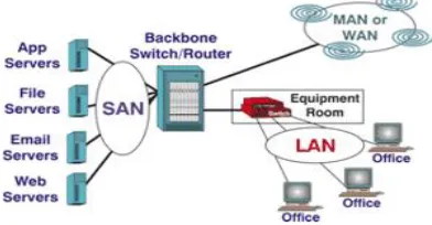
[image:3.612.313.525.190.505.2]All networks involve the same basic principle: information can be sent to, shared with, passed on, or bypassed within a number of computer stations (nodes) and a master computer (server). Network applications include LANs, MANs, WANs, SANs, intra building and inter building communications, broadcast distribution, intelligent transportation systems (ITS), telecommunications, supervisory control and data acquisition (SCADA) networks, etc. In addition to its oft-cited advantages (i.e., bandwidth, durability, ease of installation, immunity to EMI/RFI and harsh environmental conditions, long-term economies, etc.), optical fiber better accommodates today's increasingly complex network architectures than copper alternatives. Figure 3 illustrates the interconnection between these types of networks.
Fig 3 Interconnections between Different Network Types
Networks can be configured in a number of topologies. These include a bus, with or without a backbone, a star network, a ring network, which can be redundant and/or self-healing, or some combination of these. Each topology has its strengths and weaknesses, and some network types work better for one application while another application would use a different network type. Local, metropolitan, or wide area networks generally use a combination, or "mesh" topology. An advanced version of the ring network uses two communication cables sending information in both directions. Known as a counter-rotating ring, this creates a fault tolerant network that will
redirect transmission in the other direction, should a node on the network detect a disruption. This network uses fiber optic transceiver, one controlling unit in set in "master" mode along with several nodes that have been set as "remote" units. The first remote data transceiver receives the transmission from the master unit and retransmits it to the next remote unit as well as transmitting it back to the master unit. An interruption in the signal line on the first ring is bypassed via the second ring, allowing the network to maintain integrity. Figure 4 illustrates this configuration as it might be used in a ITS installation.
[image:3.612.41.237.408.510.2]Fig 4 Self-healing Ring Topolog
Fig 5 24-node mesh topology
[image:3.612.317.503.537.642.2]This is the mesh network which seems like a matrix. A row goes from 0 to n-1 and column also. So there are total of n rows and n column. Above diagram shows grid of NxN. In this adjacent nodes are connected to each other. Any node can be represented with the designation (i, j) where i stands for the row number goes from 0 to n-1 and j stands for column number goes from 0 to n-1. In this type of networks horizontal-vertical routing and zig zag routing techniques are implemented to route the data from source to destination. In this thesis we are using the same topology i.e. grid topology.
4. DATA TRANSMISSION TYPES
Internet implements packet switching technology where all the packets are provided with IP addresses. The MTU size is 1500 bytes that carries all types of application data i.e. data; voice and video which is also termed as triple play technology. Certain problem in IP network are describe in later chapter however IP packet carrying data performance is efficient as compare to voice and video data. In an ISP IP network, the forwarded traffic performs the destination IP address lookup in the router to send the data to desire destination. Which means an external IP prefix exists in the routing table of every ISP network router. Border Gateway Protocol (BGP) is responsible for both external internet and customer prefixes so every router of an ISP network must depend upon BGP protocol. While MPLS perform packet forwarding through label lookup only associated with egress router. Thus the label contains information regarding the packet for every intermediate router in the network instead of core router present at ISP network. Only MPLS edge router need to run BGP to perform destination IP address lookup to forward the packet in an ISP, IP network.
5. MPLS (MULTI PROTOCOL LABEL
SWITCHING)
MPLS is evolved through ATM and frame relay VAN networks; MPLS uses labels to advertise between different routers by means of label mapping through label switching mechanism. Previously frame relay uses frames while ATM uses cells to map labels, to label switching techniques, frames cannot be of fix length while the cells consists of fix length with 5 bytes of header and 48 bytes of payload. ATM
and frame relay are identical in a way when label traversing each hop in the network causes the label to change the header value. This differentiate from the traditional IP network when IP packets are forwarded through router it does not change the value at the header of the IP packet i.e. destination IP address. MPLS also adds the label at the ingress Label Edge Router (LER) of the MPLS network, changes the label value at each LER within MPLS network until it reaches the egress LER, where completely removes the MPLS label and the data packet is forwarded towards destination IP address[Digvijaysinh Parmar] The reason for implementing IP technology in early stage was such that label switching technology was slower and routers forward the IP packets toward the destination IP address by looking at the IP header and finding exact match in the
[image:4.612.316.532.321.477.2]routing table.
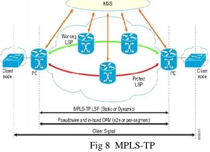
Fig 8 MPLS-TP
MPLS-TP ring protection mechanisms as a novel protection mechanism, which aggregates merits of both wrapping and steering approaches. The present article describes the implementation in detail and shows that the new approach highly reduces packet loss compared to the current mechanism[1]. A new architecture for MPLS-based micro mobility management Optimized I-NMPLS is a hierarchical approach to support micro-mobility. This approach integrates the traffic engineering and QoS capabilities of MPLS with Mobile IP Fast Authentication protocol (MIFA) as a mobility management framework.[2]. MPLS is a next generation backbone architecture, it can speed up packet forwarding to destination by label switching. Therefore, fault recovery has become an important research area in MPLS Traffic Engineering[3]. A MPLS based routing algorithm is present for reducing the number of MPLS labels to N + M without increasing any link load. Presented explicit N + M bound makes it easy to limit the table size requirement for a planed network, and the linearity allows for tables implemented in fast memory. For differentiated services with K traffic classes with different load constraints, Presented bound increases to K(N+M). Presented stack-depth is only one, justifying implementations of MPLS with limited stack-depth[4].This paper describes design, implementation, and capability of a MPLS simulator, which suppaas label swapping operation, LDP, CR-LDP, and various sorts of label distribution function. It enables researchers to simulate how a U P is established and terminated, and how the labelled packets act on the LSP.
In order to show MPLS simulator's capability, the basic MPLS function defined in MPLS standards is simulated; label distribution schemes, flow aggregation, ER-LSP, and LSP Tunnel[5]. They introduces a T-MPLS simulation tool developed using OPNET modeler 11.5. Author proposed a simulation node structure including four layers, i.e. Client Layer, Adaptation Layer, Control Layer and the Switching & Forwarding Layer. All the L2 (PDH, SONET/SDH, ETH, FR, ATM, etc) and L3 (IP) payload could be mapped into T-MPLS tunnel through either MPLS encapsulated method or pseudo wire mechanism[6]. Author provide some performance measurements comparing the prototype to software routers. The measurements indicate that the prototype is an appropriate tool for achieving line speed forwarding in testbeds and other experimental networks[7] A work on Mobile MPLS with Route
Optimization is presented by the author and proposes a route optimization protocol to overcome this problem in Mobile MPLS. By adding a correspondent agent function to Mobile MPLS's edge routers, the mobility binding of a mobile node can be cached by the edge routers and the packet routing to the mobile node can be route-optimized[8].
7. PROBLEM DEFINED
In a high speed network, any disturbance over the network cause heavy data loss. When data is transferring a topology like bus or ring. The chance of data loss increases more in same ratio. In this present the discussion is being performed on high speed MPLS Ring network. As some fault occurs over the network it will return heavy data loss.
8. SIGNIFICANCE OF WORK
As we know a distributed network is required to share the information as well as the resources. Because of this as the number of nodes in the network increases the communication or the load over the network increases and data loss chances will be increases. This noise increases the congestion and data loss that results information loss is increase in transmission. In short we can say as the network traffic is increases and the QOS decreases. In some topologies this degradation in the QOS is heavy. Such as in transmission through a node can have heavy data transmission loss due to the network. The proposed work will resolve this problem; improve the Quality of Service (QOS) by sharing and utilizing the bandwidth efficiently.
9. REFERENCES
[1] A.Abid, F.M. Abbou, and H.T. Ewe, Vol. 2 (2005), “Staged
Reservation scheme for Optical Burst Switching
Networks,” IEICE Electronics Express, No. 11 pp.327-332.
[2] A.Abid, Member, IEEE, F. M. Abbou, H. T. Ewe, Senior Member, IEEE, 14-17 May (2007 ), On the Congestion Control in Optical Burst Switching Networks Proceedings of the 2007
[3] Ali Diab, Rene Boringer, (2006) “Optimized I-MPLS: A Fast and Transparent Micro-Mobility-Enabled MPLS
Framework”
[4] Bin Li, Yongjun Zhang, Shanguo Huang, Wanyi G, (2009)
“Cascaded Packet Transfer Schemes to Improve Wireless
T-MPLS Network Bandwidth Efficiency”, 978
-1-4244-3693-4/09 ©2009 IEEE.
[5] Ching-Fang Hsu, Te-Lung Liu, and Nen-Fu Huang, (2002)
“On the deflection routing in QoS supported optical burst
-switched Networks”, IEEE International Conference on
2001) “Network Reliability and Fault Tolerance”, IEEE
Transactions on Volume 50, Issue 1, Page(s):85–91. [6] Rajkumar and Dr.N.S.Murthy Sharma, November (2008) ,
"A Distributed Priority Based Routing Algorithm for Dynamic Traffic in Survivable WDM Networks", International Journal of Computer Science and Network Security, vol.8, no.11.
[7] Savinya Polvichai, (2011), “Mobile MPLS with Route
Optimization: The Proposed Protocol and Simulation
Study”.
[8] Wenjun Xie, Shanguo Huang, Wanyi Gu, (2010) “AN
IMPROVED RING PROTECTION METHOD IN
MPLS-TP NETWORKS”.
[9] Yimin Qiu, (2010) , “A Research of MPLS-based Network