Technology (IJRASET)
Performance Analysis of Three Phase Five-Level
Inverters Using Multi-Carrier PWM Technique
Bhanutej Jawabu Naveez
Assistant Professor, Vignana Bharathi Institute of Technology, Aushapur, Ghatkesar, Hyderabad. Telangana, INDIA
Abstract--This Paper presents investigation of most popular topologies so called Cascaded H-Bridge Multilevel Inverter, Neutral Point Clamped or the Diode Clamped Multilevel Inverter and flying Capacitor five-level Inverter. Detail analysis of each inverter with switching tables, advantages and disadvantages are discussed in detail. For generating pulses to control the inverter a multi-carrier pulse width modulation technique has used. Using multi-carrier based POD technique for all converters phase voltages, line voltages and FFT analysis are drawn. The comparative results of the harmonic analysis have been obtained using MATLAB/SIMULINK software for three inverters and it is found fruitful with diode-clamped multi-level inverter with THD percentage.
Keywords— Multi-level inverter, Total Harmonic distortion, Switching losses.
I. INTRODUCTION
Numerous industrial applications have begun to require higher power apparatus in recent years. Some medium voltage motor drives and utility applications require medium voltage and megawatt power level. For a medium voltage grid, it is troublesome to connect only one power semiconductor switch directly. As a result, a multilevel power converter structure has been introduced as an alternative in high power and medium voltage situations. A multilevel converter not only achieves high power ratings, but also enables the use of renewable energy sources. Renewable energy sources such as photovoltaic, wind, and fuel cells can be easily interfaced to a multilevel converter system for a high power application [1-3]. The concept of multilevel converters has been introduced since 1975 [4]. The term multilevel began with the three-level converter [5]. Subsequently, several multilevel converter topologies have been developed [6-13]. However, the elementary concept of a multilevel converter to achieve higher power is to use a series of power semiconductor switches with several lower voltage dc sources to perform the power conversion by synthesizing a staircase voltage waveform. Capacitors, batteries, and renewable energy voltage sources can be used as the multiple dc voltage sources. The commutation of the power switches aggregate these multiple dc sources in order to achieve high voltage at the output; however, the rated voltage of the power semiconductor switches depends only upon the rating of the dc voltage sources to which they are connected. A multilevel converter has several advantages over a conventional two-level converter that uses high switching frequency pulse width modulation (PWM). The attractive features of a multilevel converter can be briefly summarized as follows.
Staircase waveform quality: Multilevel converters not only can generate the output voltages with very low distortion, but also can reduce the dv/dt stresses; therefore electromagnetic compatibility (EMC) problems can be reduced.
Common-mode (CM) voltage: Multilevel converters produce smaller CM voltage; therefore, the stress in the bearings of a motor connected to a multilevel motor drive can be reduced. Furthermore, CM voltage can be eliminated by using advanced modulation strategies such as that proposed in [14].
Input current: Multilevel converters can draw input current with low distortion.
Switching frequency: Multilevel converters can operate at both fundamental switching frequency and high switching frequency PWM. It should be noted that lower switching frequency usually means lower switching loss and higher efficiency.
Technology (IJRASET)
the literature: cascaded H-bridges converter with separate dc sources, diode clamped (neutral-clamped), and flying capacitors (capacitor clamped). Moreover, abundant modulation techniques and control paradigms have been developed for multilevel converters such as sinusoidal pulse width modulation (SPWM), selective harmonic elimination (SHE-PWM), space vector modulation (SVM), and others. In addition, many multilevel converter applications focus on industrial medium-voltage motor drives [11, 15, 16], utility interface for renewable energy systems [17], flexible AC transmission system (FACTS) [18], and traction drive systems [19].
This chapter reviews state of the art of multilevel power converter technology. Fundamental multilevel converter structures and modulation paradigms are discussed including the pros and cons of each technique. Particular concentration is addressed in modern and more practical industrial applications of multilevel converters. A procedure for calculating the required ratings for the active switches, clamping diodes, and dc link capacitors including a design example are described. Finally, the possible future developments of multilevel converter technology are noted.
II. MULTI-LEVEL INVERTERS
As previously mentioned, three different major multilevel converter structures have been applied in industrial applications: cascaded H-bridges converter with separate dc sources, diode clamped, and flying capacitors. Before continuing discussion in this topic, it should be noted that the term multilevel converter is utilized to refer to a power electronic circuit that could operate in an inverter or rectifier mode. The multilevel inverter structures are the focus of in this chapter; however, the illustrated structures can be implemented for rectifying operation as well.
A. Cascaded Multi-Level Inverter
A single-phase structure of an m-level cascaded inverter is illustrated in Figure 31.1. Each separate dc source (SDCS) is connected to a single-phase full-bridge, or H-bridge, inverter. Each inverter level can generate three different voltage outputs, +V
dc, 0, and –Vdc by connecting the dc source to the ac output by different combinations of the four switches, S1, S2, S3, and S4. To obtain +Vdc,
switches S
1 and S4 are turned on, whereas –Vdc can be obtained by turning on switches S2 and S3. By turning on S1 and S2 or S3 and S4, the output voltage is 0. The ac outputs of each of the different full-bridge inverter levels are connected in series such that the
synthesized voltage waveform is the sum of the inverter outputs. The number of output phase voltage levels m in a cascade inverter is defined by m = 2s+1, where‘s’ is the number of separate dc sources. An example phase voltage waveform for an 11-level cascaded H-bridge inverter with 5 SDCSs and 5 full bridges is shown in Figure 31.2. The phase voltage van = va1 + va2 + va3 + va4 +
va5.
For a stepped waveform such as the one depicted in Figure 31.2 with s steps, the Fourier Transform for this waveform follows [15, 19]
V(ωt) = ∑ [cos( ) + cos( ) + … … . . + cos( )] ( ) where n=1, 3, 5 ,7…
Technology (IJRASET)
Figure.2 Output phase voltage waveform of an 11-level cascade inverter with 5 separate dc sources
Manjrekar has proposed a cascade topology that uses multiple dc levels, which instead of being identical in value are multiples of each other [27-28]. He also uses a combination of fundamental frequency switching for some of the levels and PWM switching for part of the levels to achieve the output voltage waveform. This approach enables a wider diversity of output voltage magnitudes; however, it also results in unequal voltage and current ratings for each of the levels and loses the advantage of being able to use identical, modular units for each level.
The main advantages and disadvantages of multilevel cascaded H-bridge converters are as follows [29, 30]. Advantages:
The number of possible output voltage levels is more than twice the number of dc sources (m = 2s + 1).
The series of H-bridges makes for modularized layout and packaging. This will enable the manufacturing process to be done more quickly and cheaply.
Disadvantages:
Separate dc sources are required for each of the H-bridges. This will limit its application to products that already have multiple SDCSs readily available.
B. Diode-Clamped Multilevel Inverter
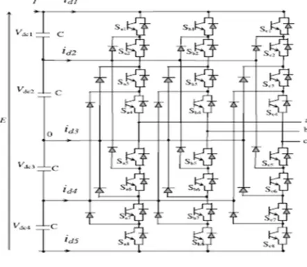
The neutral point converter proposed by Nabae, Takahashi, and Akagi in 1981 was essentially a three-level diode-clamped inverter [5]. In the 1990s several researchers published articles that have reported experimental results for four-, five-, and six-level diode-clamped converters for such uses as static var compensation, variable speed motor drives, and high-voltage system interconnections [18-31]. A three-phase six-level diode-clamped inverter is shown in Figure 31.5. Each of the three phases of the inverter shares a common dc bus, which has been subdivided by five capacitors into six levels. The voltage across each capacitor is Vdc, and the
voltage stress across each switching device is limited to V
dc through the clamping diodes. Table 31.1 lists the output voltage levels possible for one phase of the inverter with the negative dc rail voltage V0 as a reference. State condition 1 means the switch is on,
and 0 means the switch is off. Each phase has five complementary switch pairs such that turning on one of the switches of the pair requires that the other complementary switch be turned off. The complementary switch pairs for phase leg a are (S1, S2) and (S3, S4).
[image:4.612.217.393.73.280.2]Technology (IJRASET)
Figure.3 Five-level NPC inverter
[image:5.612.205.426.78.270.2]For a m-level diode-clamped inverter has an m-level output phase voltage and a (2m-1)-level output line voltage.
Table I: Switching states and teriminal voltages of five-level inverter
States Sx1 Sx2 Sx3 Sx4 Sx5 Sx6 Sx7 Sx8 Vxo
P2 1 1 1 1 0 0 0 0 2E
P1 0 1 1 1 1 0 0 0 E
O 0 0 1 1 1 1 0 0 0
N1 0 0 0 1 1 1 1 0 -E
N2 0 0 0 0 1 1 1 1 -2E
Each blocking diode has the same voltage rating as the active switches, Dn will require ‘n’ diodes in series similarly, the number of
diodes required for each phase would be (m-1) × (m-2). Thus, the number of blocking diodes is quadratically related to the number of levels in a diode-clamped converter.
The main advantages and disadvantages of multilevel diode-clamped converters are
Advantages
All of the phases share a common dc bus, which minimizes the capacitance requirements of the converter. For this reason, a back-to-back topology is not only possible but also practical for uses such as a high-voltage back-back-to-back inter-connection or an adjustable speed drive.
The capacitors can be pre-charged as a group.
Efficiency is high for fundamental frequency switching.
Disadvantages
Real power flow is difficult for a single inverter because the intermediate dc levels will tend to overcharge or discharge without precise monitoring and control.
The number of clamping diodes required is quadratically related to the number of levels, which can be cumbersome for units with a high number of levels.
C. Flying Capacitor Multilevel Inverter
Technology (IJRASET)
of the flying capacitor multilevel inverter is shown in Figure. 4 This topology has a ladder structure of dc side capacitors, where the voltage on each capacitor differs from that of the next capacitor. The voltage increment between two adjacent capacitor legs gives the size of the voltage steps in the output waveform
Figure.4 Five-Level Flying capacitor MLI
One advantage of the flying-capacitor-based inverter is that it has redundancies for inner voltage levels; in other words, two or more valid switch combinations can synthesize an output voltage. Table 31.2 shows a list of all the combinations of phase voltage levels that are possible for the six-level circuit shown in Figure 31.7. Unlike the diode-clamped inverter, the flying-capacitor inverter does not require all of the switches that are on (conducting) be in a consecutive series. Moreover, the flying-capacitor inverter has phase redundancies, whereas the diode-clamped inverter has only line-line redundancies [2, 3, 33]. These redundancies allow a choice of charging/discharging specific capacitors and can be incorporated in the control system for balancing the voltages across the various levels.
In addition to the (m-1) dc link capacitors, the m-level flying-capacitor multilevel inverter will require (m-1) × (m-2)/2 auxiliary capacitors per phase if the voltage rating of the capacitors is identical to that of the main switches. One application proposed in the literature for the multilevel flying capacitor is static var generation [2, 3]. The main advantages and disadvantages of multilevel flying capacitor converters are as follows [2, 3].
Advantages:
Phase redundancies are available for balancing the voltage levels of the capacitors.
Real and reactive power flow can be controlled.
The large number of capacitors enables the inverter to ride through short duration outages and deep voltage sags.
Disadvantages:
Control is complicated to track the voltage levels for all of the capacitors. Also, precharging all of the capacitors to the same voltage level and startup are complex.
Switching utilization and efficiency are poor for real power transmission.
The large numbers of capacitors are both more expensive and bulky than clamping diodes in multilevel diode-clamped converters. Packaging is also more difficult in inverters with a high number of levels.
Technology (IJRASET)
A. Matlab Simulink Design of Five-Level Cascaded Multi-Level Inverter
Figure.6 Five-level Cascaded Multi-level Inverter using MATLAB/Simulink
Figure.7 Gate pulse generation using Multi-carrier PWM
Figure.8 Triggering Pulses to the inverter
Technology (IJRASET)
Figure.9 Line Voltages of five-level Cascaded MLI
Figure.10 FFT analysis for Five-level cascaded Inverter
A. Matlab/Simulink Design Of Five-Level Diode-Clamped MLI
Technology (IJRASET)
Figure.13 Line Voltages of five-level Diode-clamped MLI
Figure.14 FFT analysis for Five-level diode-clamped ML Inverter
B. Matlab/Simulink Design Of Five-Level Flying Capacitor MLI
Figure.15 Simulink design of five-level Capacitor-clamped MLI
Technology (IJRASET)
Figure.17 Line Voltages of five-level flying capacitor MLI
Figure.18 FFT analysis for flying capacitor MLI
IV. CONCLUSION
This paper is proposed with comparative analysis of cascade H-bridge multi-level inverter, Diode-clamped multi-level inverter and flying capacitor multi-level inverter. As multi-level inverters are popular because of their output voltage waveform near to sinusoidal, here these three topologies are designed using matlab/simulink model design software and are compared for total harmonic distortion using FFT analysis Tool. It is observed that diode-clamped multi-level inverter has low THD about 16.81% when Phase opposition disposition technique is used as the PWM control
REFERENCES
[1] J. Rodriguez, J. S. Lai and F. Z. Peng, “Multilevel Inverters: Survey of Topologies, Controls, and Applications,” IEEE Transactions on Industry Applications,
vol. 49, no. 4, Aug. 2002, pp. 724-738.
[2] J. S. Lai and F. Z. Peng, “Multilevel Converters-A new Breed of Power Converters,” IEEE Trans. Ind. Applicat., vol.32,pp. 509-517, May/June 1996.
[3] L. M. Tolbert, F. Z. Peng, and T. Habetler, “Multilevel Converters for Large Electric drives,” IEEE Trans. Ind. Applicat.,vol.35,pp. 36-44, Jan./Feb. 1999.
[4] R. H. Baker and L. H. Bannister, “Electric Power Converter,” U.S. Patent 3 867 643, Feb. 1975.
[5] A. Nabae, I. Takahashi, and H. Akagi, “A New Neutral-point Clamped PWM inverter,” IEEE Trans. Ind. Applicat., vol. IA-17, pp. 518-523, Sept./Oct. 1981.
[6] R. H. Baker, “Bridge Converter Circuit,” U.S. Patent 4 270 163, May 1981.
[7] P. W. Hammond, “Medium Voltage PWM Drive and Method,” U.S. Patent 5 625 545, Apr. 1977.
[8] F. Z. Peng and J. S. Lai, “Multilevel Cascade Voltage-source Inverter with Separate DC source,” U.S. Patent 5 642 275, June 24, 1997.
[9] P. W. Hammond, “Four-quadrant AC-AC Drive and Method,” U.S. Patent 6 166 513, Dec. 2000.
[10] M. F. Aiello, P. W. Hammond, and M. Rastogi, “Modular Multi-level Adjustable Supply with Series Connected Active Inputs,” U.S. Patent 6 236 580, May
2001.
[11] M. F. Aiello, P. W. Hammond, and M. Rastogi, “Modular Multi-Level Adjustable Supply with Parallel Connected Active Inputs,” U.S. Patent 6 301 130,Oct.
2001.
[12] J. P. Lavieville, P. Carrere, and T. Meynard, “Electronic Circuit for Converting Electrical Energy and a Power Supply Installation Making Use Thereof,” U.S.
Patent 5 668 711, Sept. 1997.
[13] T. Meynard, J.-P. Lavieville, P. Carrere, J. Gonzalez, and O. Bethoux, “Electronic Circuit for Converting Electrical Energy,” U.S. Patent 5 706 188, Jan. 1998.
[14] E. Cengelci, S. U. Sulistijo, B. O. Woom, P. Enjeti, R. Teodorescu, and F. Blaabjerg, “A New Medium Voltage PWM Inverter Topology for Adjustable Speed
Drives,” in Conf. Rec. IEEE-IAS Annu. Meeting, St. Louis, MO, Oct. 1998, pp. 1416-1423.
Technology (IJRASET)
Jan/Feb. 1999, pp. 36-44.