Technology (IJRASET)
Three Phase Grid Connected Photovoltaic systems
Using Effective Linear Stabilization System with
fuzzy logic controller
N.Radhakrishna1, G.Vijay kumar2
1
M.Tech Student, EEE, DVR& Dr.HS MIC College of Technology, Andhrapradesh, India
2
Associate Professor, EEE, DVR& Dr.HS MIC College of Technology, Andhrapradesh, India
Abstract: This paper presents a robust linear stabilization scheme for a three-phase grid-connected solar system to control the output current of solar cell connected to the grid and dc-link voltage to extract maximum output power from solar units. The scheme is mainly based on the design of a robust controller using a feedback linearization approach, where the robustness of the proposed scheme is ensured by undertaking nonlinearities within the solar system model. In this paper, the nonlinearities are modelled as designed nonlinearities are based on the matching of satisfactory conditions. The performance of the proposed linearization scheme is evaluated on a three-phase grid-connected solar system in terms of delivering maximum power under undesirable conditions.
Index Terms—Grid-connected solar system, matching conditions, nonlinear controller, partial feedback linearizing scheme, structured nonlinearity.
I. INTRODUCTION
The utilization of grid-connected solar systems is increasingly being pursued as a supplement and an alternative to the conventional fossil fuel generation in order to meet increasing energy demands and to limit the pollution of the environment. The major concerns of integrating PV into the grid are stochastic behaviours of solar irradiations and interfacing of inverters with the grid. Because of high initial investment, changes in solar irradiation, and reduced life-time of PV systems, as compared with the traditional energy sources, it is beneficial to extract maximum power from PV systems. Maximum power point tracking (MPPT) techniques are widely used to extract maximum power from the PV system that is delivered to the grid through the inverter. Interconnections among PV modules within a shaded PV field can affect the extraction of maximum power. A study of all possible shading scenarios and interconnection schemes for a given PV field, to maximize the output power of PV array, is proposed in previous methodology. Inverters interfacing PV modules with the grid perform two major tasks—one is to ensure that PV modules are operated at maximum power point (MPP), and the other is to inject a sinusoidal current into the grid. In order to evaluate these tasks effectively, we need one efficient control schemes are essential .In a grid-connected PV system, control objectives are met by a strategy using a pulse width modulation (PWM) scheme.
Technology (IJRASET)
Fig. 1. Three-phase grid-connected PV system.
Analysis and the controller design of nonlinear uncertain PV systems remains an important and challenging area. Since the feedback linearization technique is widely used in the design of nonlinear controllers for power systems, this paper proposed the extension of the partial feedback linearizing scheme, by considering uncertainties within the PV system model. In this paper, matching conditions are used to model the uncertainties in PV systems for given upper bounds on the modeling error, which include parametric and state-dependent uncertainties. These uncertainties are bounded in such a way that the proposed controller can guarantee the stability and enhance the performance for all possible perturbations within the given upper bounds of the modeling errors of nonlinear PV systems. The effectiveness of the proposed controller is tested and compared with that of a partial feedback linearizing controller without uncertainties, following changes in atmospheric conditions.
II. PHOTOVOLTAIC SYSTEM MODEL
The schematic diagram of a three-phase grid-connected PV system, which is the main focus of this paper, is shown in Fig. 1. The considered PV system consists of a PV array, a dc-link capacitor C, a three-phase inverter, a filter inductor L, and grid voltages ea , eb , ec . In this paper, the main aim is to control the voltage vdc (which is also the output voltage of PV array vpv ) across the capacitor C and to make the input current in phase with grid voltage for unity power factor by means of appropriate control signals through the switches of the inverter.
A. Photovoltaic Cell and Array Model
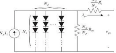
A PV cell is a simple p-n junction diode that converts the irradiation into electricity. Fig. 2 shows an equivalent circuit diagram of a PV cell that consists of a light generated current source IL , a parallel diode, a shunt resistance Rsh , and a series resistance Rs. In Fig. 2, ION is the diode current that can be written as
ION = Is [exp [α (vpv + Rs ipv )] − 1] (1)
where α = q AkTC, k = 1.3807 × 10⁻²³ JK−1 is the Boltzmann’s constant, q = 1.6022 × 10⁻¹⁹ C is the charge of electron, TC is
the cell’s absolute working temperature in Kelvin, A is the p-n junction ideality factor whose value is between 1 and 5, Is is the saturation current, and vpv is the output voltage of the PV array which is also the voltage across C, i.e., vdc. Now,
Fig.2 Equivalent circuit diagram of the PV array
[image:3.612.178.373.564.653.2]Technology (IJRASET)
B. Three-Phase Grid-Connected Photovoltaic System Model
In the state-space form, Fig. 1 can be represented through the following equations
Where Ka, Kb , and Kc are the input switching signals. Now, by applying KCL at the node where the dc link is connected, we obtain
v˙pv =1/C (ipv − idc). (7)
However, the input current of the inverter idc can be written as [19]
idc = iaKa + ibKb + icKc (8)
v˙pv =1/C ipv −1/C (iaKa + ibKb + icKc ) (9)
III. OVERVIEW OF PARTIAL FEEDBACK LINEARIZING STABILIZATION SCHEME
As the three-phase grid-connected PV system as represented by (10) has two control inputs (Kd and Kq) and two control outputs (Iq and vpv), the mathematical model can be represented by the following form of a nonlinear multi input multi output (MIMO) system:
x˙ = f(x) + g1 (x)u1 + g2 (x)u2 y1 = h1 (x) (10)
The partial feedback linearizing scheme transforms the nonlinear grid-connected PV system into a partially linearized PV system, and any linear controller design technique can be employed to obtain the linear control lawfor the partially linearized system. However, by the partial feedback linearizing scheme before obtaining a control law , it is essential to ensure the partial feedback linearizability and internal dynamics stability of the PV system. The details of partial feedback linearizability and internal dynamics stability of the considered PV system are presented in [18] from where it can be seen that the PV system is partially linearized and that the internal dynamic of the PV systems is stable. The partially linearized PV system can be written as
z1 = −ωId –R/LIq –Eq/L+ vpv/LKq = v1 (11)
z2 =1/Cipv −1/CIdKd −1/CIqKq = v2 (12)
z represents the transformed states, and v represents the linear control inputs that are obtained through the PI design approach [18]. The nonlinear control law can be written as Equation (15) is the final control law that is obtained through a partial feedback linearizing scheme, and the controller ensures the stability of the PV system for the considered nominal model and exact parameters of the system need to be known. However, in practice, it is very difficult to determine the exact parameters of the system. Thus, the considered partial feedback linearizing scheme is unable to maintain the stability of the PV system with changes in system conditions and the consideration of uncertainties within the PV system is necessary, which is shown in the following section.
IV. ROBUST CONTROLLER DESIGN
This section aims the derivation of the robust control law that robustly stabilizes a grid-connected PV system with uncertainties whose structures are already discussed in the previous section. The following steps are followed to design the robust controller for a three-phase grid-connected PV system.
A. Step 1 (Partial feedback linearization of grid-connected PV systems)
Technology (IJRASET)
z1 =Lf h1 (x)+L f h1 (x)+[Lg1 h1 (x)+L g1 h1 (x)]u1+ [Lg2 h1 (x) + L g2 h1 (x)]u2 z2 =Lf h2 (x)+L f h2 (x)+[Lg1 h2 (x)+L g1 h2 (x)]u1+ [Lg2 h2 (x) + L g2 h1 (x)]u2 . For the PV system, the partially linearized system can written as
If v1 and v2 are linear control inputs for the aforementioned partially feedback linearized system, (21) can be written as
which can be obtained using any linear control technique, and in this paper, here we are using two PI controllers
Fig.3 Implementation block diagram
before designing and implementing the controller based on partial feedback linearizing scheme, it is essential to check the stability of the internal dynamics that is similar to that described in
B. Step 2 (Derivation of robust control law):
From (22), the robust control law can be obtained as follows:
Equation (23) is the final robust control law for a three grid connected PV system, and the modeled uncertainties are involved in control law. The main difference between the designed robust control law (23) and the control law (15) is the inclusion of uncertainties within the PV system model. The performance of the designed robust stabilization scheme is evaluated and compared in the following section with our previously published partial feedback linearizing scheme with no uncertainties [18]. The performance of the controller is evaluated in the following section.
Technology (IJRASET)
in order to achieve good performance. However, for real life grid-connected PV systems, there often exist inevitable uncertainties within the constructed models. In addition, there exist uncertain parameters that are not exactly known or are difficult to estimate. Therefore, to evaluate the performance of the designed robust control scheme, it is essential to consider these uncertainties.The implementation block diagram of the proposed scheme is shown Fig. 4, in which the modeled uncertainties have been included with the nominal PV system model. From Fig. 4, it can also be seen that the three-phase grid voltages and currents are transformed into
direct and quadrature axis components through abc − dq transformation that is done to match with the proposed modeling presented
in Section II. The designed scheme is the combination of linear PI controllers and the partial feedback linearizing scheme. Finally,
the control inputs are again transformed into three-phase components using dq − abc transformation to implement them through the
inverter switches. To make the input signals suitable for switches, a PWM technique is used. The designed stabilization scheme is validated through the simulation and experimental results in the following sections.
A. Simulation Results
Fig.4 Three Phase Grid Connected Photovoltaic system Using Effective Linear Stabilization System with fuzzy logic controller
Technology (IJRASET)
Fig.6 Performance under changing atmospheric conditions
Fig.7 Performance under a three-phase short-circuit fault
Fig.8 Performance under a single-phase short-circuit fault
VI. CONCLUSION
In this paper, a robust stabilization scheme is considered by modeling the uncertainties of a three-phase grid-connected solar system based on the satisfaction of matching conditions to ensure the operation of the system at unity power factor. In order to design the robust partial scheme, we are using partial feedback linearization approach, and with the designed scheme, only the upper bounds of the PV systems’ parameters and states need to be known rather than network parameters and nature of the faults. The resulting robust scheme enhances the overall stability of a three-phase grid connected PV system, considering admissible network uncertainties. Thus, this stabilization scheme has good robustness against the PV system parameter variations, irrespective of the network parameters and configuration. Future work will include the implementation of the proposed scheme on a practical system.
REFERENCES
[1] S. Jain and V. Agarwal, “A single-stage grid connected inverter topology for solar PV systems with maximum power point tracking,” IEEE Trans. Power Electron., vol. 22, no. 5, pp. 1928–1940, Sep. 2007.
Technology (IJRASET)
[3] T. Esram and P. L. Chapman, “Comparison of photovoltaic array maximum power point tracking techniques,” IEEE Trans. Energy Convers., vol. 22, no. 2, pp. 439–449, Jun. 2007.
[4] I. Houssamo, F. Locment, and M. Sechilariu, “Maximum power point tracking for photovoltaic power system: Development and experimental comparison of two algorithms,” Renewable Energy, vol. 35, no. 10, pp. 2381–2387, Oct. 2010.
[5] U. Zimmermann and M. Edoff, “A maximum power point tracker for long-term logging of PV module performance,” IEEE J. Photovoltaics, vol. 2, no. 1, pp. 47–55, Jan. 2012.
AUTHORS DETAILS
N.RadhaKrishna completed his M.Tech in Power Electronics from DVR&Dr.HS MIC college of technology in the year 2016. Hecompleted his B.Tech from Amrita Sai Institute of Science and Technology in the year 2013.