© 2016, IRJET | Impact Factor value: 4.45 | ISO 9001:2008 Certified Journal
| Page 61
Effect of Process Parameters on Material Removal Rate in µ-EDM of
Magnesium Nano-Composite
Skandesh B.L, K.M Mathew, R Oyyaravelu, P Kuppan,
School of mechanical Engineering, VIT University, Tamil Nadu, India
---***---
Abstract -
Electrical discharge machining (EDM) is amanufacturing process in which electrical discharges are used to bring about a desired shape of a workpiece. In this research work, the material removal rate (MRR) is studied by optimizing the µ-EDM process parameters such as pulse on time, pulse off time, voltage gap and duration. The work materials used was Magnesium nanocomposites (reinforced with 1.98% and 2.50% Titanium Carbide). The experiment was designed as per L9 orthogonal array method. Taguchi analyses were carried out in finding the significant factors which causes changes in MRR. Pulse on time was found to have the most significant impact on MRR while pulse off time and voltage gap were found to have a relatively lesser impact on MRR.
Key Words: µ-EDM, Magnesium Nanocomposite, MRR, Taguchi, Titanium Carbide
1. INTRODUCTION
There has been an increase in demand for the application of lightweight materials in the aerospace, automobile and biomedical industries. Although magnesium is a soft metal, metal matrix composites based on magnesium are difficult to machine using conventional methods [1]. Inaccuracy in drilling micro sized holes, rapid tool wear and breakage of tool are some of the common problems associated with conventional machining methods [2]. Therefore, there comes a need to use advanced technology or non-traditional methods to machine these composites.
Electrical Discharge Machining (EDM) is one of the nonconventional methods used for machining metal matrix composites. It is a noncontact process that makes it well suited for materials that cannot take stress of traditional machining. Drilling is an imperative process to access the structural durability of the composite [3]. Therefore, it is fundamental that the drilled micro sized holes have minimum tolerances and burrs. There comes a need to use light weight nanocomposite materials. Therefore, this experiment is aimed at observing and analyzing process parameters that effect the material removal rate when micro sized holes are drilled in magnesium nanocomposite samples. EDM has been used to drill these micro sized holes since it is a high precision drilling method. Also, EDM is
used in order to ensure minimal surface roughness and burrs.
2. PRINCIPLE OF EDM
An electrical spark is created between the electrode and workpiece. Intense heat with temperatures reaching 8000 to 12000 degrees Celsius is produced by the spark. The material is removed from the workpiece by rapidly occurring spark discharge [4].
Fig-1 : Machining principle of EDM.
3. EXPERIMENTAL SETUP
The experiment was conducted on ELECTRONICA small-hole super drill ED 32U. The dielectric fluid used is distilled water. Experiments were conducted with positive polarity of electrode. The pulsed discharge current was applied in various steps in positive mode.
3.1 Selection of tool material
For this experiment brass has been selected as the tool material of diameter 0.5 mm. The reasons for selecting
the brass as a tool material are as follows: i. High electrical conductivity
© 2016, IRJET | Impact Factor value: 4.45 | ISO 9001:2008 Certified Journal
| Page 62
3.2 Selection of Work Piece Material
For this experiment, the work material used was magnesium nanocomposites (reinforced with 1.98% and 2.50% Titanium Carbide). It is a lightweight and futuristic material in automotive and aerospace applications due to its attractive properties.
3.3 Selection of Process Parameters
There are many process parameters in EDM like peak current, gap voltage, pulse on time, pulse off time, current density etc. But in this work, gap voltage, pulse on time and pulse off time have been selected as variable parameters. The ranges variable process parameters have been found by conducting the trial runs and from the literature survey.
3.4 Selection of Range of Process Parameters
The process parameters are taken in L9 orthogonal array system.i. Current (I): It was maintained at 3 A which is an optimised value to ensure efficient material removal by arcing. The feed rate was optimized at 3 µm/s throughout the experiment so as to prevent burring of hole inner surface.
ii. Gap Voltage (V): It is a potential difference between the electrode (tool) and work piece. When this gap voltage reaches a sufficient value the discharge takes place and causes significant effect in the MRR of workpiece.
iii. Pulse on time (Ton): The experiment has been conducted at 5µs, 7µs and 9µs depicting L9 Orthogonal array system. A higher value of Ton causes excessive heating which may cause defect in the workpiece [5]. A lower value reduces machining time, thereby causing a reduction in MRR.
iv.
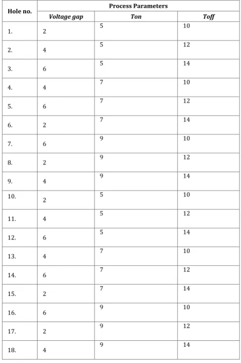
Pulse off time : The experiment has been conducted at 10µs, 12µs and 14µs. A low value of Toff may cause inconsistent cycling and therefore lead to retraction of the incoming servo or slowing down the operation cycle [5]. [image:2.595.315.559.136.504.2]The experiments were designed as per Taguchi design of experiments. For each reinforcement, 9 experiments were performed as suggested by Taguchi orthogonal array. The experimental matrices for 1.98% and 2.50% reinforcement of Titanium Carbide are shown in Table 1 and Table 2 respectively.
Table – 1 : Experimental matrix for 1.98%(hole 1-9) and 2.5%(hole 10-18) TiC
Hole no. Process Parameters
Voltage gap Ton Toff
1. 2 5 10
2. 4 5 12
3. 6 5 14
4. 4 7 10
5. 6 7 12
6. 2 7 14
7. 6 9 10
8. 2 9 12
9. 4 9 14
10. 2 5 10
11. 4 5 12
12. 6 5 14
13. 4 7 10
14. 6 7 12
15. 2 7 14
16. 6 9 10
17. 2 9 12
18. 4 9 14
3.5 Determination of Material Removal Rate
The amount of metal removed from the workpiece by the electrode for a specific time is known as Material© 2016, IRJET | Impact Factor value: 4.45 | ISO 9001:2008 Certified Journal
| Page 63
3.6 Signal to Noise Ratio
Traditional and experimental design methods are too complex in determining the most efficient range of parameters. Also, a large number of experimental parameter variables have to be inputted to deliver contrasting results [9]. Therefore, Taguchi method solves this task by using a special design called L9 orthogonal array which consists of a small number of experiments. The S/N ratio can be used derive performance characteristics which depend on the controlled output parameters.
[image:3.595.30.287.354.416.2]The category selected to study the S/N ratio is “Bigger is better” for MRR. Therefore, the optimal level of the process parameters is the level with the highest S/N ratio. The maximum MRR was obtained at the following conditions.
Table-2: Optimum condition for MRR
%TiC V Ton Toff
1.98 4 9 14
2.5 2 9 14
4. EXPERIMENTAL RESULTS AND DISCUSSION
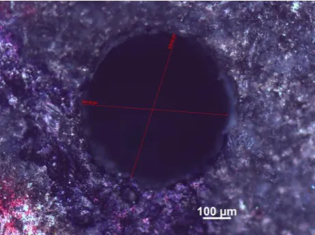
The drilled hole is depicted as shown in Figure 2 with diameter measured using a microscope.Fig-2
EDM Drilled hole sample
Table-3 : S/N ratio for MRR for 1.98%TiC and 2.5%TiC
4.1 Effect of Input Parameters on MRR
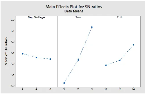
[image:3.595.314.580.496.660.2]The value of input parameters and output parameters were analyzed using Taguchi method. The rankings given in Table 3, It states the degree of influence by the input parameters on MRR. The results show that Ton has highest significant followed by Toff and voltage for both the reinforcements. The S/N ratio curve for MMR was plotted as a method to visualize varying effect of the input parameters on MRR.
Figure 3 Main Effects Plot for SN ratio for 1.98% TiC
1.98% Voltage gap(V) Ton(µs) Toff(µs)
Delta 0.1896 2.9342 0.7391
Rank 3 1 2
2.50% Voltage gap(V) Ton(µs) Toff(µs)
Delta 0.2464 2.5552 0.9245
[image:3.595.36.267.516.688.2]© 2016, IRJET | Impact Factor value: 4.45 | ISO 9001:2008 Certified Journal
| Page 64
Figure 4
Main Effects Plot for SN ratio for 2.5% TiC4.1.1 Effect of Pulse on time
It can be inferred of from the graphs, the material removal rate increases proportionally with increasing pulse on time [10]. The pulse on time was varied between 5 and 9. The reason for the increased MRR is due to the increased spark energy as the pulse on time increases [11]. It can be also inferred from Figure 3 that changes in pulse on time causes the maximum change in MRR.
4.1.2 Effect of Pulse off Time
The pulse off time is varied between 10 to 14. The material removal rate as inferred from the graph is found to increase steadily from 10 to 12 and then increase at a very low rate from 12 to 14. It is interesting to note that during pulse off time there is no material removal, however the reason for increased MRR is attributed to better flushing of micro debris during long pause time which results in improved MRR [12].
4.1.3 Effect of Voltage Gap
The voltage gap of the corresponding experiments is varied between 2 to 6 V. The Material removal rate is found to increase from 2 to 4 V and then decrease from 4V to 6V for 1.98% TiC reinforcement where as for 2.5% TiC reinforcement it decreases with the increase in volatage for the range od process parameters tested.. The possible reason for the decrease in MRR at high gap voltages is decreased gap current.
5. CONCLUSION
In this paper, micro holes of diameter around 500 µm were drilled in magnesium nanocomposites reinforced with TiC using EDM. The effect of process parameters on MRR have been studied and optimized. The main conclusions from the experimental results are given below:
The MRR increases with the increase on pulse on time for both 1.98% and 2.5% TiC reinforcements. The pulse on time has high significant (I-rank) on MRR. The maximum MRR was obtained at high level of pulse on time.
As the pulse off time increases, the MRR shows increasing trend within the range of investigation. The Taguchi analysis shows that pulse off time has II- rank on the MRR. The maximum MRR was obtained at high level of pulse off time.
The MRR decreases at high gap voltages for both the reinforcements. The maximum MRR was obtained at middle level (4 V) for 1.98% TiC and at low level (2 V) for 2.5% TiC reinforcement. The voltage gap seems to induce a very less change in MRR.
REFERENCES
[1] K. Ponappa, S. Aravindan, P. V. Rao, J. Ramkumar & M.
Gupta, “The effect of process parameters on machining of magnesium nano alumina composites through EDM”, International Journal of Advanced Manufacturing Technology, February 2009.
[2] Wai Leong Eugene Wong, Manoj Gupta,
“Magnesium-Based Nanocomposites: Lightweight Materials of the Future”, Materials Characterization 105, April 2015K.
[3] Shape Memory Alloys” Int. J. Electrochem. Sci., 8
(2013) 3095 - 3104
[4] Shivendra Tiwari, “Effect of Different Process
Parameters on Over Cut in Optimizing of Electrical Discharge Machining (EDM) Process” International Journal of Engineering Research & Technology (IJERT), Vol. 2 Issue 7, July – 2013, ISSN: 2278-0181
[5] Harpreet Singh, Amandeep Singh, “Effect of Pulse
On/Pulse Off Time On Machining Of AISI D3 Die Steel Using Copper And Brass Electrode In EDM” International Journal of Engineering and Science ISSN: 2278-4721, Vol. 1, Issue 9 (November 2012), PP 19-22
[6] M. Siva, M. Parivallal, M. Pradeep Kumar,
“Investigation on the effect of process parameters in micro electrical discharge machining” Procedia Materials Science 5 (2014) 1829-1836. [International Conference on Advsnces in Manufacturing and Materials Engineering, AMME 2014]
[7] Harmanpreet, Manpreet Singh, Bipendeep,
© 2016, IRJET | Impact Factor value: 4.45 | ISO 9001:2008 Certified Journal
| Page 65
[8] Harmanpreet, Manpreet Singh, Bipendeep,
“Optimization of EDM Process Parameters Using Shape Memory Alloys” Int. J. Electrochem. Sci., 8 (2013) 3095 - 3104
[9] M. Robertsagayadoss, P. Parthiban, “Parametric
Optimization of MRR and Surface Roughness in E.D.M Using By Taguchi Method” International Journal of Applied Engineering Research ISSN 0973-4562 Volume 11, Number 5 (2016) pp 3207-3210
[10] J. Laxman, K. Guru Raj, P. Venkateswara Rao, “EDM
Process Parameters effects on Titanium Super Alloy” International Research Journal of Engineering and Technology (IRJET), Volume: 02 Issue: 09 Dec-2015
[11] M. Siva, M. Parivallal, M. Pradeep Kumar,
“Investigation on the effect of process parameters in micro electrical discharge machining” Procedia Materials Science 5 (2014) 1829-1836. [International Conference on Advsnces in Manufacturing and Materials Engineering, AMME 2014
[12] Prasad A Jadhav, Prof. Bhaskar B Borkar, “Analysis and