© 2016, IRJET | Impact Factor value: 4.45 | ISO 9001:2008 Certified Journal
| Page 1469
Analysis of Powered Roller Conveyor
Shital bhosale
1, A.V.Gaur
2,
1
M.E.Student (Mechanical-Design Engineering), Brahmdevdada Mane Institute of Technology, Solapur
.
Maharashtra, India
2
Assistant Professor (Department of Mechanical Engineering), Brahmdevdada Mane Institute of Technology,
Solapur,
Maharashtra, India
---***---Abstract -
One of the major equipment in material handlingis roller conveyor. As the roller conveyors are not generally subjected to complex state of stress they are designed by providing higher factor of safety .In this study failure of analysis of Powered roller conveyor is carried out for changing to loads. This work is under taken to do Analysis and optimization of Powered roller Conveyor using FEA for solving above Problem. Aim-In the present work, an attempt is made to reduction in weight of existing roller conveyor by optimizing the critical parts of (e.g. Inner & outer diameter of Roller, Thickness of Roller) conveyor without hampering its structural strength. Optimization gives optimum design for same loading condition with huge amount of weight reduction. Using this procedure and using practical available structure 29.82% weight reduction is achieved. Without affecting functional performance.
Key Words
:
Optimized design, Weight reduction, and material handling systems.
1. INTRODUCTION
A conveyor system is a common piece of mechanical handling equipment that moves materials from one location to another. Conveyors are especially useful in applications involving the transportation of heavy or bulky materials. Conveyors are used when material is to be moved frequently between specific points over a fixed path and when there is a sufficient flow volume to justify the fixed conveyor investment.
Conveyor systems allow quick and efficient transportation for a wide variety of materials, which make them very popular in the material handling and packaging industries. Many kinds of conveying systems are available, and are used according to the various needs of different industries. Conveyor systems are commonly used in many industries, including the automotive, agricultural, computer, electronic, food processing, aerospace, pharmaceutical, chemical, bottling and canning, print finishing and packaging. Many factors are important in the accurate selection of a conveyor system. It is important to know how the conveyor system will be used beforehand. Some individual areas that are helpful to consider are the required conveyor operations, such as transportation, accumulation and sorting, the material sizes, weights and shapes and where the loading and pickup points need to be.
2.
PROBLEM
DEFINITION
In discussion with industry we came across problem, existing powered roller assembly fails in the running conditions when moving pallet wt on roller assembly is changed from & above 1000 Kg. Due to change in pallet wt above 1000 kg Failure of roller assembly is observed, which affects production
.
Total load is taken 2000kg. (Added factor of Safety)3. DESIGN OF PRESENT SHAFT
3.1. Material – MS
E
= 2.00×10⁵ Mpa, ρ= 7800 Kg/m3, Syt = 1050 Mpa Considering uniformly distributed load & FOS =2 Allowable Stress (ςall) = Syt / Fs = 1050/2=525 Mpa W=Pallet Weight x Factor of Safety=1000 x 2 =2000 Kg
3.2. Maximum Stress Calculation for given condition- W= 2000/4= 500 kg (Load act on 4 rollers at a time) d = Outer diameter of Shaft = 20 mm
L = Length of Shaft = 666 mm
y = Distance from neutral axis = 20/2 = 10 a = Distance of Bearing from shaft end =45 mm l= Distance between two bearing center =576 mm Considering beam with uniformly distributed load, Maximum Moment (Mmax) :-
Mmax =Wa = 5000×45 Mmax = 225000 N-mm
Moment of Inertia (I) = π (d4) / 64 = π (204) /64 I = 7850 mm4 Maximum bending stress (σb)
(
ςb) = Mmax × y/ I(ςb) = Mmax × y/ I = 225000 × 10/ 7850 (ςb) = 286.62 Mpa
Checking Factor of Safety for design- Fs = ςall / ςb
= 525/286.62 Fs = 1.8316
© 2016, IRJET | Impact Factor value: 4.45 | ISO 9001:2008 Certified Journal
| Page 1470
3.3. Maximum Deflection (Ymax) (Ymax) = wa2 (2a+3l)/6EI
= (5000×452) * (2×45 + 3×576)/ (6 x7850×2.00×105) = 200000× (1818)/ (6×1.57× 109)
ymax = 1.9541 mm
3
.4. Weight of Shafts=
cross-section area*width * mass density* number of shafts= π (0.010) 2 / 2*0.666*7800*18 = 29.3610 Kg
3.5 BEARING SELECTION:
3.5.1 Standard SKF deep groove ball Bearing,
SKF Bearing number 6204, ISI No.-20BC02, Weight =0.11 Kg d= Bore diameter = 20 mm
D=Outer diameter = 47 mm B= width = 14 mm
Bearing is suitable for High radial loads, economical.
3
.5.2 Total weight of Bearing= 36×0.11 = 3.96 kg
4. DESIGN OF PROPOSED SHAFT
4.1. Material – MSE= 2.00×10⁵ Mpa, ρ= 7800 Kg/m3, Syt = 1050 Mpa
Considering uniformly distributed load & FOS =2 Allowable Stress (ςall) = Syt / Fs = 1050/2=525 Mpa
4.2. Maximum Stress Calculation for given condition- W= 2000/4= 500 kg (Load act on 4 rollers at a time) d = Outer diameter of Shaft = 20 mm
L = Length of Shaft = 666 mm
y = Distance from neutral axis = 20/2 = 10 a = Distance of Bearing from shaft end =20 mm l= Distance between two bearing center =626 mm Considering beam with uniformly distributed load,
Maximum Moment (Mmax):- Mmax =W× a
= 5000 × 20 Mmax = 100000 N-mm
Moment of Inertia (I)
=
π (d4) / 64= π (204) /64
I = 7850 mm4
Maximum bending stress (σb) (ςb) = Mmax × y/ I
(ςb) = Mmax × y/ I = 100000 * 10/ 7850 (ςb) = 127.39 Mpa
4.3. Checking Factor of Safety for design- Fs = ςall / ςb
= 525/127.39 Fs = 4.1213
As Calculated Fs is greater than assumed Fs, Selected Material & design can be considered as safe.
4.4. Maximum Deflection (Ymax) (Ymax) = wa2 (2a+3l)/6EI
= (5000×202) * (2×20 + 3×626)/(6x 7850×2.00×105)
= 200000× (1918)/ (6×1.57× 109)
ymax = 0.4072 mm
[image:2.595.302.559.343.714.2]As compared to length 626 mm deflection of 0.4072 mm is very small. Hence selected design can be considered as safe.
Table No. 05- Comparison of Analytical Result of Present Shaft and Proposed Shaft
description Present Shaft Proposed Shaft Unit
Maximum Bending Stress 286.62 127.39 Mpa Checking factor of safety
for design 1.8316 4.1213
Deflection 1.9541 0.4072 mm
4.5.RESULT FROM ANSYS 14.5 FOR PRESENT
SHAFT
Deformation in Present Shaft
© 2016, IRJET | Impact Factor value: 4.45 | ISO 9001:2008 Certified Journal
| Page 1471
RESULT FROM ANSYS 14.5 FOR PRPPOSED SHAFT
Deformation in Proposed Shaft
Stresses in Proposed Shaft
description Existing Shaft Redesign Shaft Unit
Analytical Ansys Analytical Ansys
Maximum Bending
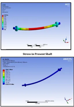
Stress 286.62 296.1 127.39 136.34 Mpa
Deflection 1.9541 2.080 0.4072 0.3720 mm
5. DESIGN OF PRESENT ROLLER
5.1. Material – MSE= 2.00×10⁵ Mpa, ρ= 7860 Kg/m3, Syt = 520 Mpa Considering uniformly distributed load & FOS =2 Allowable Stress (ςall) = Syt / Fs = 520/2=260 Mpa 5.2. Maximum Stress Calculation for given condition W= 2000/4= 500kg (Load act on 4 rollers at a time) D1= Outer diameter of roller = 60 mm
D2 = Inner diameter of roller = 44 mm
w = Width of roller = 560 mm
y = Distance from neutral axis = 60/2= 30
Considering beam with uniformly distributed load, Maximum Moment (Mmax) :-
(Mmax) = W×L2/8
= (5000×560 x 560) /8 Mmax = 196000 Nmm Moment of Inertia (I) = π (D14 - D24)/64
= π (604 – 444)/64
I = 451959 mm4
Maximum bending stress (σb) (ςb) = Mmax × y/ I
(ςb) = Mmax × y/ I
= 196000 × 30/ 451959 (ςb) = 13.01 Mpa
5.3. Checking Factor of Safety for design- Fs = ςall / ςb
= 260/13.01 Fs = 19.9838
As Calculated Fs is greater than assumed Fs, Selected Material & design can be considered as safe. Hence wt reduction can be possible.
5.4. Maximum Deflection (ymax) = 5×W×L3/384EI
(ymax) = 5×W×L3/384EI
= (5×5000*5603) / (384*2.00*105* 451959)
ymax = 0.126 mm
As compared to length 560 mm deflection of 0.126 mm is very negligible. Hence selected Roller can be considered as safe.
5. 5.Weight of Rollers -
= cross-section area× width ×mass density× number of rollers
= π (602 - 442) ×560×7860×18/4
=103.4918 Kg
6.0 Need of Optimization
As factor of safety Rollers is very high there is scope of weight reduction in this component.
Selection of Critical Parameter Roller Outer diameter
Roller Inner diameter Roller thickness
7. DESIGN OF PROPOSED ROLLER
7.1. Material – MSE= 2.00×10⁵ Mpa, ρ= 7860 Kg/m3, Syt = 520 Mpa Considering uniformly distributed load & FOS =2 Allowable Stress (ςall) = Syt / Fs = 520/2=260 Mpa 7.2. Maximum Stress Calculation for given condition W= 2000/4= 500kg (Load act on 4 rollers at a time) D1= Outer diameter of roller = 60 mm
D2 = Inner diameter of roller = 50 mm
w = Width of roller = 603 mm
y = Distance from neutral axis = 60/2 = 30
© 2016, IRJET | Impact Factor value: 4.45 | ISO 9001:2008 Certified Journal
| Page 1472
Maximum Moment (Mmax):- ((Mmax) = W×L2/8
= (5000×603 *603)/8 Mmax = 227255 Nmm
Moment of Inertia (I) = π (D14 - D24)/64
= π (604 – 504)/64
I = 329209 mm4
Maximum bending stress (σb) (ςb) = Mmax × y/ I
(ςb) = Mmax × y/ I
= 227255 × 30/ 329209 (ςb) = 20.709 Mpa
Checking Factor of Safety for design- Fs = ςall / ςb
= 260/20.709 Fs = 12.555
As Calculated Fs is greater than assumed Fs, Selected Material & design can be considered as safe.
7.3. Maximum Deflection (ymax) = 5×W×L3/384EI
(ymax) = 5×W×L3/384EI
= (5×5000×6033) / (384×2.00×105× 329209)
ymax = 0.217 mm
As compared to length 560 mm deflection of 0.158 mm is very negligible. Hence selected Roller can be considered as safe.
7.4. Weight of Rollers -
= cross-section area ×width ×mass density× number of Rollers = π (602 - 502) ×603×7860×18/4
=73.67 Kg
8. DESIGN ANALYSIS AFTER WEIGHT REDUCTION After studying number of iteration for various Parts of roller conveyor a optimized design can be selected on the basis of following parameter.
9. RESULT FROM ANSYS 14.5 FOR PRESENT ROLLER
Deformation in Present Roller
© 2016, IRJET | Impact Factor value: 4.45 | ISO 9001:2008 Certified Journal
| Page 1473
RESULT FROM ANSYS 14.5 FOR PROPOSED ROLLER
Deformation in Proposed Roller
Stress in Proposed Roller
Results- Compared Effect of Present Design of Roller with Proposed design
Sr.
No. Name of Component Weight (Kg) Existing Design Optimized Design
1 Rollers 103.49 73.67
2 Shafts 29.36 29.36
3 Bearing 03.90 03.90
Total Weight 136.75 106.93
9.1 Observation from Ansys Results- Effect of Proposed Design compared with Present design-
Design Analytical Calculation Ansys Result
Max. Def.
mm Max. Stress N /mm2)
Max. Def. mm
Max. Stress. N/mm2) Present 0.126 13.01 0.1339 13.889
Proposed 0.217 20.709 0.2083 21.641
10. Weight reduction due to Optimization
Design Weight
(Kg) % Material required compared To Existing design
% Material save compared To Existing design
Present 136.75 100
-
Proposed 106.93 70.18 29.82
3. CONCLUSIONS
Existing design calculation shows the factor of safety is very greater than requirement and there is a scope for weight reduction.
• Critical parameter which reduces the weight is roller outer diameter, roller Inner outer and roller thickness.
• Though value of deflection, stress is more in case of Optimized design, but it is allowable.
• 29.82 % of weight reduction is achieved due to Optimized design.
29.82 Kg. weight reduction achieved by optimized design than existing design.
REFERENCES
[1] S. M. Shinde, R.B. Patil, Optimization Technique Used for the Roller Conveyor System for Weight Reduction, International Journal of Engineering Research & Technology (IJERT) ,Vol.1 Issue 5, July – 2012, 1-10. [2] Gaikwad S.S and E.N. Aitavade, Transient Analysis of
roller conveyor for weight optimization. Rising Research Journal Publication, 2013, 93-98.
[3] Mr. Rajratna A. Bhalerao, Dr. R.J. Patil, Transient and Mode Shape Analysis of Gravity Roller Conveyor for Weight Reduction. International Journal of Innovative Science, Engineering & Technology, Vol. 1 Issue 5, July 2014, 112-117.
© 2016, IRJET | Impact Factor value: 4.45 | ISO 9001:2008 Certified Journal
| Page 1474
[5] Pawar Jyotsna, D.D Date, Pratik Satav, Design andoptimization of roller in belt conveyor system for weight reduction. Proceedings of 10th IRF International Conference,01st June-2014, Pune, India, 129-132. [6] Suhas M. Shinde and R.B. Patil, Design and Analysis of a
Roller Conveyor System for Weight Optimization and Material Saving .International Journal on Emerging Technologies 3(1): (2012), 168-173 .