2016 International Conference on Computational Modeling, Simulation and Applied Mathematics (CMSAM 2016) ISBN: 978-1-60595-385-4
Evaluation of Electromagnetic Performance of Emerging
Failures in Electrical Machines
Rafael Guzmán-Cabrera
1,*, Adrian Gonzalez-Parada
1, Hector Estrada Garcia
1and Jose Rafael Guzmán-Sepulveda
21
Engineering Division, University of Guanajuato. Carr. Salamanca-Valle de Santiago Km 3.5 +1.8 Km. Comunidad de Palo Blanco, Salamanca, Gto México. C.P. 36885 2
CREOL, The College of Optics and Photonics, University of Central Florida. 4304 Scorpius St., Orlando, FL 32816
*Corresponding author
Keywords: Electromagnetic performance, Magnetic field simulation, Failure detection.
Abstract. In the present paper, electromagnetic simulations of electric motors with early failures are presented. One of the most common failures in induction motors with squirrel cage rotor is considered in this paper. These failures are: broken rotor bars and short circuit in the inter-turn winding. The broken rotor bars failure was simulated with two consecutive broken bars in order to see how the magnetic flux density is affected. The inter-turn short circuit was simulated with the 40% reduction of winding coil in an inter-turn short circuit for one of the phases. In both cases the simulation was performed with the finite element software FEMM and the waveform of the flux density in both the motor air gap and the magnetic core was calculated. Comparative test of the real failure was performed in order to verify the results obtained from the simulation, good agreement between simulation and experimental measurements was obtained.
Introduction
The breakdown of induction motors is due to three main reasons which constitute the most common failures: bearing failure or defects, the rotor broken bars, and the inter-turn short-circuit in the winding [1]. The detection of these failures becomes of great importance because they are extremely difficult to detect without specialized equipment. The inter-turn short-circuit in the winding can be generated by moisture, heating by an overload, inferior quality in the insulation, among some other factors. If these faults are detected in an early stage it is possible to repair the motor and prevent greater damages, otherwise the motor will breakdown severely.
These failures have been widely studied and several methods have been adopted in order to improve the detection techniques [2-3]. In this work, we propose a hybrid technique using finite element simulation and computational algorithms to model, process, and analyze the electrical signals related to the failures of inter-turn short-circuit in the winding and the rotor broken bars. The obtained results permit defining a set of characteristics that later allow performing reliable detection, diagnosis, and discrimination between these two kind of failures.
Rotor Broken Bars
The occurrence of a rotor asymmetry will result in a backward rotating field at slip frequency with respect to the forward rotating rotor. The overall effect resulting is the induction of an EMF and current in the stator winding at frequency:
(
) (
)
1 1 2
sb
f = f − s Hz
(1) where fsb is the slip frequency sideband with respect to the rotor, f1 is the supply frequency (Hz), and s
is per unit slip. This is known as a twice slip frequency sideband due to the broken rotor bars. Therefore, a cyclic variation of the current causes a torque pulsation at twice slip frequency (2sf1) and
the corresponding speed oscillation that is equally a function of the drive inertia. This oscillation speed can reduce the magnitude of the f1(1-2s) sideband but a current upper sideband component of
f1(1+2s) is induced in the stator winding due to rotor oscillation [6]. This upper sideband is also
enhanced by the third harmonic flux.
Stator winding failures. Many works that can be found in the literature have approached the analysis of airgap and axial flux signals to detect shorted turns in the winding. The mathematical formulations can be found in references [7-8]. Previous works have demonstrated that the following equations give the components in the air gap flux waveform as a function of shorted inter-turns.
(
)
1 1
st
n
f f s k
p
= − ±
(2)
where fst, represents the components as a function of shorted turns; f1, is the supply frequency; n and k
are constants; p is the amount of pole pairs, and s is the slip. If a short circuit in the winding occurs, a new path for the current circulation is formed. This new path causes a decrease of the coil impedance of the winding due to the reduction of the coil turns (i.e. turns that were in the series now are connected in parallel). The main consequence of this kind of failure is the increment of the total current flow through the shorted circuit winding. This additional current causes a temperature increase and then progressive failure of machine insulation.
Motor Specifications
The electrical machine analyzed is an induction motor with squirrel cage rotor whose characteristics are: 7.5 HP, 220V. Double, Slots/coil: 1-7 and turns 59.
The materials used for Finite Element Analysis (FEA) simulations were: Rotor and Stator: M15 Steel; Bars: Aluminum 6061 T6; Winding wire: Cu 22 AWG. The general characteristics and magnetic properties are included in the simulation and are identified for each part of the motor.
In order to simulate the winding section, three electric circuits were created; each circuit corresponds to a phase of the motor supply. In each of these circuits a current of 1.5 A and phases of 0º, 120º, and -120º of the corresponding current of an electric system in a polar configuration were implemented as follows: Circuit phases A: 1.5 A. Circuit phases B: -0.75+I*1.29903811 A. Circuit phases C: -0.75-I*1.29903811 A. In the simulation, the motor winding was connected to double star in order to obtain a connection to 220 V. A general drawing of the motor was done taking into consideration a general winding distribution and the real dimensions of the rotor bars.
FEA Simulation
Simulation of Motor without Failure
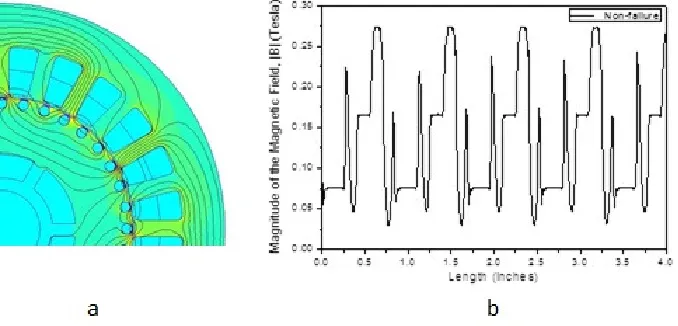
[image:3.612.133.472.157.320.2]The simulation of the motor without failure was developed according to the general specifications for the motor and the materials mentioned above. The results obtained from the simulation for the flux density and the flux lines inside the stator core are shown in Figure 1. The magnetic poles can be seen as well as the uniform magnetic flux density around the motor and no distortion of flux in the air gap and the stator is observed (see Figure 1a).
Figure 1. Magnetic field distribution of a Motor without failure: a) Simulation of Magnetic flux distribution, b) Magnetic field distribution in the airgap.
The analysis of the magnetic flux in the air gap between rotor and stator could be made considering the magnetic field performance in the middle. The magnetic field distribution in the air gap can be observed in Figure 1a. This distribution is uniform throughout the section analyzed, the distortion observed is due to be harmonic performance of the magnetic flux in the airgap between the rotor and the stator.
Simulation of Broken Bars in the Rotor
The broken bar condition in an induction motor with a squirrel cage rotor can be simulated considering the current absence in the bars analyzed. In this case, two consecutive bars were chosen for simulation purposes. Materials and motor specifications were the same as those mentioned above. The results obtained are presented in Figure 2, the location where the failure is being induced has been marked with the circle. The lines of magnetic field distribution in the airgap present a distortion due to the broken bars lead to a magnetic flux increase in the failure zone; this distortion was highlighted in the Figure 2b.
[image:3.612.148.449.570.704.2]Data Processing and Analysis
Processing of the data obtained from the simulations was conducted in order to fit them to analytical expressions. The objective consists in finding analytical expressions that allow to model the experimental results precisely such that the analytical expressions can be directly compared to each other by using specific parameters such as maximum, minimum, and fundamental frequency, among others.
In this particular case, the data obtained from the numerical simulations show characteristics strongly related to periodic features, which suggest that better performance will be obtained if the experimental data are modeled using periodic functions.
A wide variety of fitting models based on periodic functions can be found, being the most common those using sinusoidal functions as a basis such as the Fourier series expansion. In this regard, Fourier series are not only the most commonly used but also the model that better fit our experimental results. Fourier series with different amount of terms were explored for the data obtained from the numerical simulations for the three cases previously performed (i.e. good condition, 40% inter-turn short circuit, and broken bars), and it was found that an 8-terms series successfully models the experimental results with R2 larger than 0.9, as can be shown in Figure 3 (A).
(A) (B)
[image:4.612.95.517.299.600.2](C)
Figure 3. Fourier Series–8 terms, Motor without failure.
Broken Bars Simulation and 40% Inter-turn Short Circuit
As mentioned previously, the model obtained from the data processing consists of an 8-term Fourier expansion.
A Summary of the Fit is Indicated Below
The analytical model is inaccurate when modeling the experimental data labeled broken bars, specifically in the region where the outstanding peak appears. However, in general terms, all three models can be considered quite accurate since they successfully model the small peak components of the experimental data.
Conclusions
Modeling the experimental dataset using Fourier series resulted in quite accurate fitting; nevertheless, the differences found through the analysis of the series coefficients seemnot to be enough to clearly differentiate the experiments, specifically those labeled “Non-failure Condition” and “40% inter-turn short Circuit”. The difference between the mean values (i.e. a0 in the Fourier series) is clearly
confirmed due to the fact that at zero frequency (DC component) the experiments labeled “Broken Rotor Bars” has the highest value. Despite some information can be extracted from the magnitude of the Fourier transform, it cannot be depicted a conclusive difference between the experimental data. On the other hand, when the phases of the Fourier transform of the experimental data are compared to each other, it can be clearly seen that at larger frequencies the experimental data are perfectly distinguishable, which allows discriminating between them.
References
[1] IEEE Motor Reliability Working Group, “Report of large motor reliability survey of industrial commercial installations” Part I, IEEE Transactions on Industrial Applications, Vol IA-21. Pp 853-872, July/Aug. 1985.
[2] W. T. Thomson, M. Fenger, “Current signature analysis to detect induction motor faults” IEEE Industry application Magazine, pp. 26-34, July/Aug. 2001.
[3] R.M. Talam, S. B. Lee, G. Stone, G. B. Kliman, J. Yoo, T. G. Habetler, R. G. Harley. “A Survey of methods for detection of stator related faults in induction machines”, The IEEE International Symposium on Diagnostics for Electrical Machines, Power Electronics and Drivers, SDEMPED 2003, Atlanta, USA. Agust. 2003. pp. 35-46.
[4] W.T. Thomson, A.Barbour, “On-line current monitoring and application of a finite element method to predict the level of static airgap eccentricity in three-phase induction motors” IEEE Transactions on Energy Conversion, Vol. 13, No. 4, pp. 347-357, Dec. 1998.
[5] J.H. Jung, J.J. Lee, B.H. Kwon, “Online diagnosis of induction motors using MCSA”, IEEE Transaction on Industrial Electronics, Vol. 53, No. 6, pp. 1842-1852, Dec. 2006.
[6] J. Faiz, B.M. Ebrahimi, B. Akin, H.A. Toliyat, “Finite Element transient analysis of induction motors under mixed eccentricity fault”, IEEE Transaction on Magnetics, Vol. 44, No. 1, pp. 66-74, Jan 2008.
[7] Sarma, Mulukutl, “Electric Machines: Steady-State Theory and Dynamic Performance”, Second Edition, PWS Publishing Company, 1996.