SERVICE MANUAL
7941 AND 7945
DISC DRIVES
Manual part no. 07940-90903 Microfiche part no. 07940-90803 PRINTED: SEP 1 985
Prin ted in U.S.A
07940-90903 E0985
FliD'l
HEWLETT
PRINTING HISTORY
New editions incorporate all update material since the previous edition. Updating Supplements, which are is-sued between editions, contain additional and revised information to be incorporated into the manual by the user. The date on the title page changes only when a new edition is published.
First Edition Change 1
Second Edition Third Edition .
SEP 1984 10 DEC 1984 JAN 1985 SEP 1985
NOTICE
The information contained in this document is subject to change: without notice.
HEWLETT-PACKARD MAKES NO WARRANTY OF ANY KIND WITH REGARD TO THIS MATERIAL, INCLUDING, BUT NOT LIMITED TO, THE IMPLIED WARRANTIES OF MERCHANTABILITY AND FITNESS FOR A PARTICULAR PURPOSE. Hewlett-Packard shall not be liable for errors contained herein or for incidental or consequential damages in connection with the furnish-ing, performance or use of this material.
This document contains proprietary information which is protected by copyright. All rights are reserved. No part of this document may be photocopied or reproduced without the prior written consent of Hewlett-Packard Company.
Fli:n-
HEWLETT
~~
PACKARD
SERVICE MANUAL
7941 AND 7945
DISC DRIVES
Manual part no. 07940-90903 Microfiche part no. 07940-90803 PRINTED: SEP 1 985
Printed in U.S.A
Serial Number Prefix
07940-90903 E0985
The main part of this manual applies directly to HP 7941 and HP 7945 Disc Drives with serial numbers prefixed 2540 and subsequent. RI~fer to Appendix B for disc drives with serial numbers prefixed 2515 and prior. Refer to Appendix A for disc drives with sel"ial numbers prefixed 2438 and prior.
OPTIONS COVERED
In addition to the standard models, this manual covers the following options: 01 5 and 550.
FOR U.S.A. ONLY
The Federal Communications Commission (in 47 CFR 15.838) has specified that the fol-lowing notice be brought to the attention of the users of this product.
FEDERAL COMMUNICATIONS COMMISSION RADIO FREQl!ENCY INTERFERENCE
STATEMENT
Warning: Thiis equipment generates and uses radio frequency energy and if not installed and used properly, that is, in
strict accordance with the manufacturer's instructions, may cause interference to radio and television reception. It has
been type tested and found to comply with the limits for a Class B computing device in accordance with the
specifiu-tions in Subpart J of Part 15 of FCC Rules, which are designed to provide reasonable protection against such
inter-ference in a I'esidential installation. However, there is no guarantee that interinter-ference will not occur in a particular
in-stallation. If this equipment does cause interference to radio or television reception, which can be determined by
turn-ing the equipment off and on, the user is encouraged to try to correct the interference by one or more of the followturn-ing measures: reclrient the receiving antenna; relocate the computer with respect to the receiver; move the computer away
from the rec.liver; plug the computer into a different branch circuit. If necessary, the user should consult the dealer or
authorized field service representative for additional suggestions. The user may find the following booklet prepared by
the Federal (~ommDnications Commission helpful: "How to Identify and Resolve Radio-TV Interference Problems". This
booklet is aV:lilable from the U.S. Government Printing Office, Washington, DC 20402. Stock No. 004-000-00345-4.
PRINTING HISTORY
New editions incorporate all update material since the previous edition. Updating Supplements, which are is-sued between editions, contain additional and revised information to be incorporated into the manual by the user. The date on the title page changes only when a new edition is published.
First Edition Change 1 Second Edition Third Edition .
SEP 1984 10 DEC 1984 JAN 1985 SEP 1985
NOTICE
The information contained in this document is subject to change without notice.
HEWLETT-PACKARD MAKES NO WARRANTY OF ANY KIND WITH REGARD TO THIS MATERIAL, INCLUDING, BUT NOT LIMITED TO, THE IMPLIED WARRANTIES OF MERCHANTABILITY AND FITNESS FOR A PARTICULAR PURPOSE. Hewlett-Packard shall not be liable for errors contained herein or for incidental or consequential damages in connection with the furnish-ing' performance or use of this material.
This document contains proprietary information which is protected by copyright. All rights are reserved. No part of this document may be photocopied or reproduced without the prior written consent of Hewlett-Packard Company.
Section I
GENERAL INFORMATION Introductiorl
Scope Of Manual Options
Related Manuals Characteristics
Section II
CHANNEL INTERFACE Introduction . . . CS/80 Instruction Set
Transaction Structure Real Time Commands .. Complementary Commands General Purpose Commands Diagnostic Commands . . . Transparent Messages Hewlett-Packard Interface Bus
HP-IB Communications
Channel Management . . . . . Parallel Poll . . . . Universal Device Clear Message Structure
Section III
THEORY OF OPERATION Introduction
Disc Format SBC PCA-A5 .
SBC Internal Bus Architecture HP-IB Data Bus . . . . RAM Di!lta Bus
Microprocessor Address Bus Microprocessor Data Bus DMA Gj!lte Array Data Bus Read/Write Data Bus Control/Status Data Bus Control/Status Read Strobe Control/Status Write Strobe Control/Status Address Bus .
CONTENTS
Page
1 -1 1 -1
1-2 1-2 1-2
Page
2-1 2-1 2-1 2-1 2-1 2-9 2-9 2-9 2-9 2-12 2-13 2-13 2-13 2-13
Page
3-1 3-3 3-5 3-5 3-6 3-6 3-6 3-6 3-6 3-6 3-6 3-6 3-6 3-7
CONTENTS (continued)
Read/Write Data Bus . . . . Data Request In/Data Request Out Data Strobe In/Data Strobe Out HP-IB Interface IC .
Microprocessor
HP-IB Address Switch Channel Status
Self-Test Switches Self-Test Display DMA Gate Array IC RAM
EXEC ROM . . . . DDC ROM . . . . Address Multiplexer Clocks And Control Logic Bu f f e rs . . . .
Typical Host Dependent Transaction
Host Dependent to Device Dependent Communications Control/Status Data and Address Buses
Read/Write Data Bus Receiver/Driver . . . . . Transceiver . . . . SBC/Disc Drive A1 Communication
Controller IC and Register Decode Logic Self-Test Register .
GPC Register
DDC Errors Register PUPO Register . . . Disc Controller IC .. Phase-Locked Loop IC La tch . . . . DMA Handshake Control Clock Generator
Disc Drive A1 . . . .
Disc Drive A1/SBC Control Communication Input Buffers . . . . Output Drivers . . . . Disc Drive A1/SBC Data Communication Microprocessor and PLA . . . Microprocessor/PLA Control Signals Clock Generator
Head-Di sc Modu Ie .. Actuator . . . Recording Medium Read/Write Heads
Read Preamplifier/Write Driver IC
Actuator Lock Driver Spindle Speed Control Spindle Speed Checker
Spindle Motor Brake Relay and Relay Driver Actuator Servo Control
Demodulator
Mode Select Switch Seek Mode
Veloc i ty DAC .. Tachometer . . . Slope Selector Current Inverter On-Peak Detector Power Amplifier Inverter
Track-Follow Mode Off-Track Detector Seek Operation
Restore to Track 0 Operation Read/Write Data Channel
Head Select and Control Logic . Read Chain . . . .
Amplifier/Signal Conditioner Differential Line Driver Write Chain
Line Receiver . . . . Transition Generator Write Current Source Write Fault Detector Self Test
Power-On Reset Power Supply A4
AC Input Circuits Switch-Mode Supply Power-On Reset
Section IV
SERVICE IN1FORMATION Introduction
Service Tools FRA Locations Cable Connectors Signal Distribution Power Distribution Signal Notation Block Diagram Test Points ..
CONTENTS (continued)
3-15 3-15 3-15 3-15 3-15 3-16 3-16 3-16 3-16 3-16 3-17 3-17 3-17 3-17 3-17 3-17 3-17 3-17 3-17 3-18 3-18 3-18 3-18 3-18 3-18 3-18 3-18 3-19 3-19 3-19 3-19 3-19 3-19 3-20 3-20
Page
4-1 4-1 4-1 4-1 4-2 4-2 4-2 4-2 4-2
CONTENTS (continued)
Self-Test Controls
Fault/On Line Indicator Sel f Test Swi tch .. Self-Test Display Display Results Switch Internal Diagnostics Sel f Tes t . . . .
Self-Test Subtests . Self-Test Error Reporting
Fault/On Line Indicator Self-Test Display ReQuest Status
ReQuest Status Example
Run Time Error and Fault Reporting External Exerciser
Amigo Clear (AMCLEAR)
Cancel Transaction (CANCEL) Test HP-IB Channel (CHANNEL)
Channel Independent Clear (CICLEAR) Clear Logs (CLEAR LOGS) . . . . Describe Selected Unit (DESCRIBE) Perform Internal Diagnostics (DIAG) Output Error Rate Test Log (ERT LOG) Exit Program (EXIT) . . . Output Fault Log (FAULT LOG) Output Help Information (HELP) Initialize Media (INIT MEDIA) Update Device Logs (PRESET) .. ReQuest Status (REQSTAT) . . . .
Perform Read-Only Error Rate Test (RO ERT) Output Run Log (RUN LOG) . . . . .
Spare (SPARE) . . . . Output Spare Table (SPARE TABLE) Output Device Table (TABLES) Perform Servo Test (SERVO) Set Unit Number (UNIT)
Perform Write-Then-Read Error Rate Test (WRT ERT) Troubleshooting
Section V
REMOVAL AND REPLACEMENT Introduction
Preparation for Service
4-2 4-2 4-3 4-3 4-3 4-4 4-4 4-4 4-5 4-5 4-5 4-6 4-7 4-8 4-8 4-8 4-8 4-8 4-8 4-8 4-8 4-8 4-9 4-9 4-9 4-9 4-9 4-9 4-9 4-10 4-10 4-10 4-10 4-10 4-10 4-10 4-10 4-10
Page
Front Panel
Fan . . . .
FRA4 (Power Supply Assembly A4) FRA1 (Disc Drive Assembly A1) .
Section VI
REPLACEABLE PARTS
Introduction
Ordering Information
Section A
APPENDIX A
CONTENTS (continued)
5-3 5-3 5-4 5-4
Page
6-1 6-1
Page
Backdating Information (Serial Numbers Prefixed 2438 and prior) . . . A-1
Section B
APPENDIX B
Page
Backdating Information (Serial Numbers Prefixed 2515 and prior) . . . B-1/8-2
Section C
APPENDIX C
Page
Service Notes . . . C-1/C-2
ILLUSTRATIONS
Figure
Transaction Structure . . . . Hewlett-Packard Interface Bus Signal Lines
Disc Recording Format Track Recording Format Disc Drive, Block Diagram
Disc Drive, Functional Block Diagram, Disc Drive, Functional Block Diagram, Disc Drive, Functional Block Diagram,
Self-Test Controls and Readout P8 Signal Source (Sheet 1 of 3) P8 Signal Source (Sheet 2 of 3) P8 Signal Source (Sheet 3 of 3)
(Sheet (Sheet (Sheet
Field Replaceable Assembly (FRA) Locations
1 of 3) 2 of 3) 3 of 3)
FRAl (Disc Drive Al), Layout and Cable Connections FRA4 (Power Supply A4), Layout and Cable Connections FRA5 (SBC PCA-A5), Layout and Cable Connections FRA4 (Power Supply A4), Test Points and Voltages Cabling Diagram
Signal Distribution .
Order of Disassembly
Disc Drive, Exploded View
Appendix A Illustrations
Appendix B Illustrations
Page
2-10 2-11
. 3-4 . 3-5 3-29/3-30 3-31/3-32 3-33/3-34 3-35/3-36
4-11 4-19 4-20 4-21 4-26 4-27 4-28 4-29 4-30 4-31/4-32 4-33/4-34
5-5/5-6
6-3
A-3
Table
Disc Drive Characteristics
Device Command Summary. Disc Drive Utilities .. HP-IB Def ini tions . . . . Universal Command Formats. HP-IB Message Structure.
Lis t 0 f Mn emo n i c s. . . . .
Single-Board Controller (Unit 2) Self-Test Subtest List . . .
Disc Drive (Unit 0) Self-Test Subtest List. Disc Drive Error Condition List.
Fault Code List ..
Diagnostic Summary . . .
Disc Drive Replaceable Parts. Abbreviaticlns . . . " . . . . Code List of Manufacturers
Appendix A Tables.
Appendix B Tables.
TABLES
Page
1-3/1-4
. 2-2 . 2-9 2-12 2-12 2-14
3-21
4-12 4-13 4-18 4-22 4-25
6-2 6-4 6-5/6-6
A-4
B-8
SAFETY CONSIDERA TIONS
GENERAL - This product and related documenta-tion must be reviewed for familiarizadocumenta-tion with safety markings and instructions before operation.
-WARNING
CAUTION
SAFETY SYMBOLS
Instruction manual symbol: the product wIll be marked with this symbol when it is necessary for the user to refer to the instruc-tion manual in order to protect the prod uc t against damage.
Indicates hazardous voltages.
Indica tes earth (ground) terminal.
The WARNING sign denotes a hazard. It calls attention to a procedure or practice which, if not correctly performed or ad-he red to, could result in personal injury. Do not proceed beyond a WARNING sign until the indi-cated conditions are fully under-stood and met.
The CAUTION sign denotes a hazard. It calls attention to an opera ting procedure or practice which, if not correctly performed or adhered to, could result in damage to or destruction of part or all of the product. Do not proceed beyond a CAUTION sign until the indicated conditions are fully understood and met.
SAFETY EARTH GROU~D - This is a safety class I product and is provIded with a protective earthing terminal. An uninterruptible safety earth ground must be provided from the main power source to the product input wiring terminals,
BEFORE APPLYING POWER - Verify that the product is configured to match the available main power source according to the input power con-figuration instructions provided in this manual.
If this product is to be operated with an autotrans-former make sure that the common terminal is connected to the earth terminal of the main power source.
SERVICING
WARNING
Any servicing, adjustment, main-tenance' or repair of this product must be performed only by service-trained personnel.
Adjustments described in this manual may be performed with power supplied to the product while protective covers are removed. Energy available at many points may, if contacted, result in per-sonal injury.
Capacitors inside this product may still be charged after the product has been disconnected from the main power source.
To avoid a fire hazard, fuses with the proper current rating and of the specified type (normal blow, time delay, etc.) must be used for replacement.
GENERAL INFORMATION
-[IJ
1 -1. INTRODUCTION
The Hewlett -, Packard 7941 and 7945 Disc Drives are medium performance, random access, data storage devic~~s designed for use with small and medium sized. computer systems. The formatted storage capacities of the HP 7941 and HP 7945 are 24 megabytes and 55 megabytes, respectively. In this manual, unless otherwise specified, "disc drive" 'refers to both the HP 7941 and HP 7945.
The disc driv«~ employs two (HP 7941) or four (HP 7945) nonremovable 130-millimetre (5.12-inch) discs for stora.ge media. Each disc surface employs one movable head to service its data tracks. The bottom surface of the lowest disc in the stack con-tains continuous prerecorded servo data which is used to ensure the precise posi tioning of the read/write he:ads.
Head positioning is performed by a rotary actuator and a c1osl~d -loop servo posi tioning system. Mechanical and contamination protection for the discs, heads, and the rotary actuator is provided by a sealed head-disc module. The head-disc module includes a self -contained air filtration system which supplie:s clean air and temperature equaliza-tion throughout the module.
Also included in the disc drive are a Hewlett-Packard Interface Bus (HP-IB)* controller and a power supply.
The disc drive contains internal self -test diagnos-tics and a fault-finding system which exercise key functions of the disc drive. Self test is performed automatically at power on and can also be initiated by the host or by a switch on the rear panel of the unit. Go/no-go test results are indicated by a green/red indicator on the front panel. If a failure occurs, information on the cause of the failure can be determine:d by viewing a 2-digit hexadecimal display on thl~ rear panel.
The disc drive is packaged in a stand -alone desktop cabinet. Accessories available include a
desk-height stand-alone cabinet designed to hold the disc drive and other desktop stack modules. A kit for rack mounting the disc drive in a standard EIA equipment rack is also available.
This manual provides all the service information needed to maintain the disc drive. Details of the control functions provided by the host computer are described in the installation documentation provided with the computer.
1 -
2.
SCOPE OF MANUAL
The manual is divided into six sections as follows: a. Section I contains a general description of the
disc drive.
b. Section II provides information about the CS/80 Instruction Set and the Hewlett-Packard Interface Bus (HP-IB).
c. Section III describes the operating principles of the disc drive.
d. Section IV contains servicing information for the disc drive, including instructions on how to use the internal diagnostics.
e. Section V supplies step-by-step removal and replacement procedures for all field-replaceable assemblies and parts in the disc drive.
f. Section VI lists and illustrates all of the field-replaceable assemblies and parts in the disc drive.
Appendix A contains backdating information about removal and replacement and replaceable parts for HP 7941 and HP 7945 Disc Drives with serial numbers prefixed with 2438 and prior. Appendix B contains backdating information about theory of operation, service information, removal and replacement, and replaceable parts
*NOTE: Not just IEEE-488, but the hardware, documentation and support that delivers the shortest path to a computation system.
General Inf orma tion 7941 and 7945
information for HP 7941 and HP 7945 Disc Drives with serial numbers prefixed 2515 and prior. Appendix C provides a listing and copy of all the service notes applicable to the HP 7941 and HP
7945 Disc Drives.
1-3. OPTIONS
Option 01 5 is the power option. The only requirement is for the switch in the power module to be placed in the proper position. Option 550 is the deletion of the Model 1083 3B HP-IB Cable from the order.
1 -4. RELATED MANUALS
For operating and installation instructions, refer to
the 7941 and 7945 Disc Drive Owner's Manual,
part no. 07940-90901, and the Site Environmental Requirements for Disc/Tape Drives
Manual, part no. 5955- 3456. For instruction set
information, refer to the CS/80 Instruction Set
Programming Manual, part no. 5955- 3442. For
addi tiona I service inf orma tion, refer to the C S / 80
External Exerciser Reference Manual, part no.
5955-3462. The CE Handbook for the HP 7941 and HP 7945 Disc Drive is part no. 07940-90905.
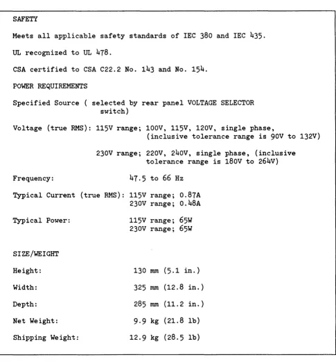
1 -5. CHARACTERISTICS
Characteristics of the disc drive, including physical dimensions and power requirements, are listed in table 1-1, Disc Drive Characteristics. Detailed specifications for the disc drive, including en-vironmental requirements, are listed in Site Environmental Requirements for Disc/Tape Drives
Manual , part no. 5955 - 3456. This publication is
Table 1-1. Disc Drive Characteristics
SAFETY
Meets
~Lllapplicable safety standards of IEC 380 and IEC 435.
UL recognized to UL 478.
CSA certified to CSA C22.2 No. 143 and No. 154.
POWER REQUIREMENTS
Specified Source ( selected by rear panel VOLTAGE SELECTOR
switch)
VoltagE~
(true RMS): 115V range; 100V, 115V, 120V, single phase,
General Information 7941 and 7945
(inclusive tolerance range is 90V to 132V)
Frequency:
230V range; 220V, 240v, single phase, (inclusive
tolerance range is 180v to 264V)
47.5 to 66 Hz
Typical Current (true RMS): 115V range; 0.87A
230V range; 0.48A
Typical Power:
SIZE
/WJt:
I GHT
Height:
Width:
Depth:
Net Weight:
Shipping Weight:
115V range; 65W
230V range; 65W
130
nun(5.1 in.)
325
nun(12.8 in. )
285
nun(11.2 in. )
9·9 kg (21.8 lb)
12·9 kg (28.5 lb)
[image:15.613.74.559.67.588.2]CHANNEL INTERFACE
-DO
2-1. INTRODUCTION
Interface to the disc drive is accomplished through Hewlett-Packard Interface Bus (HP-IB) hardware and the CS/ 8 0 Instruction Set, a set of commands formulated for mass storage devices. The following paragraphs discuss the types of CS/ 8 0 commands. Also provided is an overview of HP- IB. For full details of CS/80, refer to the CS/80 Instruction
Set Programming Manual, part no. 5955- 3442.
2-2. CS/80 INSTRUCTION SET
The increase in capabilities of both host computers and mass storage devices has emphasized the need for efficient channel communication. The CS/80 Instruction S~~t increase.s the efficiency and speed of channel operations between disc memories and their associatled host computers. Table 2-1, Device Command Summary, provides a summary of all CS/80 instructions. The CS/80 Instruction Set al:-lows a host computer to access special utilities within the disc drive. Utilities are routines stored in firmware which allow error rate tests to be per-formed and the results of such tests to be examined or logged. Utilities are listed in table 2-2, Disc Drive Utilities. Refer to the External Exerciser
Reference Manual, part no. 5955-3462, for full
details.
2-3. TRANSACTION STRUCTURE
A transaction is a logically complete operation be-tween a syst~~m host computer and a peripheral device (the disc drive) over a given channel (HP-IB). Three phases may occur during each transaction: command, execute, and report. A transaction begins when a command is received by the disc drive:, and ends when a reporting message indicating the~ status of the transaction is accepted by the host. Figure 2-1 illustrates the transaction structure, and shows the relationship between the disc drive operating states and the channel activity relative to each phase.
A unit is a separately addressable entity within a device (disc drive). A volume is a separately
ad-dressable portion of the storage media within a given unit.
2-4. REAL TIME COMMANDS
Real time commands are optimized for execution time. These commands are used most often in host/device transactions. One or more complemen-tary commands may precede a real time command in order to modify the operation of that command. Real time commands include: locate and read, 10-ca te and write, and cold load read.
2-5. COMPLEMENTARY COMMANDS
Complementary commands are used to set or up-date programmable states in the disc drive. The programmable states define characteristics such as: set unit, set address, set block displacement, set return addressing mode, set length, set burst mode, set retry time, set release, set status mask, and set Rotational Position Sensing (RPS) window size. These commands may be included within Real Time, General Purpose, or Diagnostic command messages, or they may stand alone.
When a complementary command (or commands) is embedded within another command, the para-meters or conditions established by that com-plementary command(s) are altered only for the duration of the current command. A stand-alone complementary command, however, sets the para-meters or conditions until the same stand -alone complementary command alters the set value or until power-on occurs. Power-on resets all com-plementary commands to their default values. Therefore, at power-on, length is defaulted to equal the entire volume. A stand-alone Set Length command may give it a "set" value of 1 kbyte to be used for an entire sequence of transactions, al-though some special case commands could tem-porarily override this value with an embedded complementary command to set a "current" value of 2 5 6 bytes (for 1 sector).
Channel In terf ace 7941 and 7945
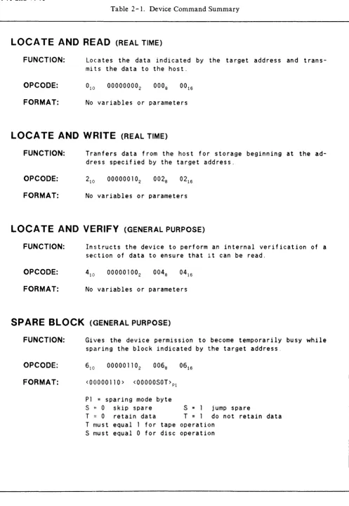
Table 2 - 1. Device Command Summary
LOCA TE AND READ
(REAL TIME) FUNCTION:OPCODE:
FORMAT:
Locates the data indicated by the target address and trans-mits the data to the host.
No variables or parameters
LOCA TE AND WRITE
(REAL TIME) FUNCTION:OPCODE:
FORMAT:
Tranfers data from the host for storage beginning at the ad-dress specified by the target adad-dress.
No variables or parameters
LOCA TE AND VERIFY
(GENERAL PURPOSE) FUNCTION:OPCODE:
FORMAT:
Instructs the device to perform an internal verification of a section of data to ensure that it can be read.
No variables or parameters
SPARE BLOCK
(GENERAL PURPOSE)FUNCTION:
OPCODE:
FORMAT:
Gives the device permission to become temporarily busy while sparing the block indicated by the target address.
<00000110> <OOOOOSOT>Pl
P1 = sparing mode byte
S
=
0 skip spare S = 1 jump spareT
= 0 retain data
T=
1 do not retain data T must equal 1 for tape operation [image:18.613.37.534.21.741.2]Channel In terf ace 7941 and 7945
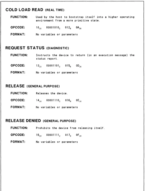
Table 2-1. Device Command Summary (continued)
COLD !LOAD READ
(REAL TIME) FUNCTION:OPCCIDE:
FORMAT:
Used by the host to bootstrap itself into a higher operating environment from a more primitive state.
1010 000010102 0128 OA16
No variables or parameters
REQUEST ST A TUS
(DIAGNOSTIC)FUNCTION:
OPCC~DE:
FORMAT:
Instructs the device to return (in an execution message) the status report.
No variables or parameters
RELEASE
(GENERAL PURPOSE) FUNCTION: Releases the device.OPCODE:
FORMAT: No variables or parameters
RELEASE DENIED
(GENERAL PURPOSE)FUNCTION: Prohibits the device from releasing itself.
OPCC)DE: 1510 000011112 0178 OF16 FORMAT: No variables or parameters
[image:19.615.65.576.48.715.2]Channel Interface 7941 and 7945
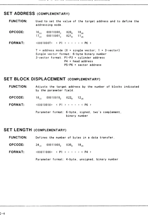
Table 2-1. Device Command Summary (continued)
SET ADDRESS
(COMPLEMENTARY)FUNCTION:
OPCODE:
FORMAT:
Used to set the value of the target address and to define the addressing mode.
1610 000100002 1710 000100012
<0001000T> < P1 > - - - - < P6 >
T = address mode (0 = single vector; 1 = 3-vector) Single vector format: 6-byte binary number
3-vector format: P1-P3 = cylinder address P4 = head address
P5-P6
=
sector addressSET BLOCK DISPLACEMENT
(COMPLEMENTARY)FUNCTION:
OPCODE:
FORMAT:
Adjusts the target address by the number of blocks indicated by the parameter field.
1810 000100102 0228
<00010010> < P1 > - - - - < P6 >
Parameter format: 6-byte, signed, two's complement, binary number
SET LENGTH
(COMPLEMENTARY)FUNCTION: Defines the number of bytes in a data transfer.
OPCODE: 2410 000110002 0308
FORMAT: <00011000> < P1 > - - - - < P4 >
[image:20.615.43.537.38.755.2]Channel In terf ace 7941 and 7945 Table 2-1. Device Command Summary (continued)
SET UNIT
(COMPLEMENTARY)FUNCTION:
OPCODE:
FORMAT:
Used to specify a specific unit within the device.
3210 001000002
3310 001000012
4710 001011112
<0010YYYY>
YYYY = unit number (1111 device controller)
INITIA TE UTILITY
(DIAGNOSTIC)FUNCTION:
FORMAT:
Directs the device to perform one utility routine.
4810 001100002 0608 30 16
4910 001100012 0618 31 16 5010 001100102 0628 32 16
<001000XX> < P1 > < n parameter bytes >
xx
=
execution message Qualifier 00 no execution message01 = device will receive execution message 10 = device will send execution message P1
=
utility number (device specific)There can be up to 8 bytes in the parameter field. The number and content of these bytes is determined by P1 .
INITIATE DIAGNOSTIC
(DIAGNOSTIC)FUNCTION:
OPCODE:
FORMAT:
Directs the device to perform one internally defined diagnos-tic routine.
51 10 001100112 0638 33 16
<00110011> < P1 < P2 > < P3 >
P1-P2
=
loop parameterP3 = diagnostic section number
NO OP
(COMPLEMENTARY)FUNCTION: Causes the device to disregard the message byte.
OPCC~DE:
FORMAT: No variables or parameters
[image:21.615.64.563.44.738.2]Channel Interface 7941 and 7945
Table 2-1. Device Command Summary (continued)
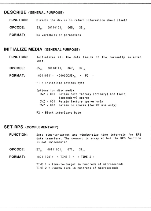
DESCRIBE
(GENERAL PURPOSE)FUNCTION: Directs the device to return information about itself.
OPCODE:
FORMAT: No variables or parameters
INITIALIZE MEDIA
(GENERAL PURPOSE)FUNCTION:
OPCODE:
FORMAT:
Initializes all the data fields of the currently selected unit.
55 10 001101112 0678 37 16
<00110111> <00000CWZ>P1 P2
Pl
=
initialize options byteOptions for disc media:
CWZ 000 Retain both factory (primary) and field (secondary) spares
CWZ 001 Retain factory spares only
CWZ 010 Retain no spares (for CE use only)
P2
=
Block interleave byteSET RPS
(COMPLEMENTARY)FUNCTION:
OPCODE:
FORMAT:
Sets time-to-target and windo\''J-size time intervals for RPS data transfers. The command is accepted but the RPS function is not implemented.
<00111001> < TIME 1 > < TIME 2 >
[image:22.612.43.537.43.732.2]Channel In terf ace 7941 and 7945 Table 2-1. Device Command Summary (continued)
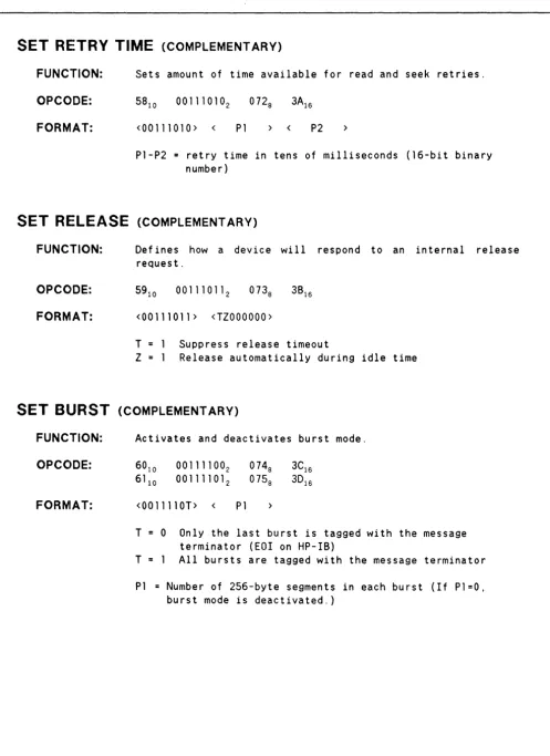
SET RETRY TIME
(COMPLEMENTARY)FUNCTION:
OPCODE:
FORMAT:
Sets amount of time available for read and seek retries.
<00111010> < P1 > < P2 >
P1-P2 = retry time in tens of milliseconds (16-bit binary number)
SET RELEASE
(COMPLEMENTARY)FUNCTION:
OPCODE:
FORMAT:
Def ines how a device will respond to an internal release request.
<00111011> <TZOOOOOO>
T Suppress release timeout
Z Release automatically during idle time
SET BURST
(COMPLEMENTARY)FUNCTION:
OPCODE:
FORMAT:
Activates and deactivates burst mode.
6010 0011110°2
6110 00111101 2
<0011110T> < P1
T 0 Only the last burst is tagged with the message terminator (EOI on HP-IB)
T All bursts are tagged with the message terminator
P1 = Number of 256-byte segments in each burst (If P1=0, burst mode is deactivated.)
[image:23.618.69.566.42.725.2]Channel Interface 7941 and 7945
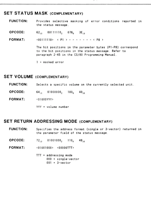
Table 2-1. Device Command Summary (continued)
SET ST A TUS MASK
(COMPLEMENTARY)FUNCTION:
OPCODE:
FORMAT:
Provides selective masking of error conditions reported in the status message.
<00111110> < P1 > - - - < P8 >
The ~it positions in the parameter bytes (P1-P8) correspond to the bit positions in the status message. Refer to
paragraph 2-45 in the CS/80 Programming Manual.
1 = masked error
SET VOLUME
(COMPLEMENTARY)FUNCTION: Selects a specific volume on the currently selected unit.
OPCODE: 6410 010000002
FORMAT: <01000YYY>
YYY
=
volume numberSET RETURN ADDRESSING MODE
(COMPLEMENTARY)FUNCTION:
OPCODE:
FORMAT:
Specifies the address format (single or 3-vector) returned in the parameter field of the status message.
7210 010010002
<01001000> <OOOOOTTT>
[image:24.615.41.535.39.716.2]Channel Interface 7941 and 7945
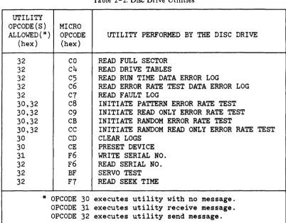
Table 2-2. Disc Drive Utilities
UTILITY
OPCODE(S)
MICRO
ALLOWED(*)
OPCODE
UTILITY PERFORMED BY THE DISC DRIVE
(hex)
(hex)
32
CO
READ FULL SECTOR
32
c4
READ DRIVE TABLES
32
C5
READ RUN TIME DATA ERROR LOG
32
c6
READ ERROR RATE TEST DATA ERROR LOG
32
C7
READ FAULT LOG
30,32
c8
INITIATE PATTERN ERROR RATE TEST
30,32
C9
INITIATE READ ONLY ERROR RATE TEST
30,32
CB
INITIATE RANDOM ERROR RATE TEST
30,32
CC
INITIATE RANDOM READ ONLY ERROR RATE TEST
30
CD
CLEAR LOGS
30
CE
PRESET DEVICE
31
F6
WRITE SERIAL NO.
32
F6
READ SERIAL NO.
32
BF
SERVO TEST
32
F7
READ SEEK TIME
*
OPCODE 30
executes utility with no message.
OPCODE 31
executes utility receive message.
OPCODE 32
executes utility send message.
2;-6. GENERAL PURPOSE COMMANDS
This command group includes commands which al-low the host to determine device type and operat-ing characteristics or to ascertain storage media in-tegrity. These commands are not considered "real time" commands and therefore should not be issued by the host unless it is willing to relinquish control of the drive for a varying period of time. General purpose commands are: locate and verify, spare block, release, release denied, describe, and initial-ize media.
2-7. DIAGNOSTIC COMMANDS
Diagnostic commands are intended to assist the host in isolating problems in the device to the replaceable assembly level. Some commands allow protected access to variables or data maintained by the device (such as error information), while others cause tests to be performed within the device, or on a specific area of the storage media. Diagnostic commands may be modified by complementary commands. Initialize diagnostic, initialize utility, and request status are all diagnostic commands.
2-8. TRANSPARENT MESSAGES
Transparent commands compensate for different types of channels and differences in operating en-vironments. Transparent commands are intercepted by the device firmware and modify the normal command -execution -reporting transaction se-quence. Transparent commands are explained in
the CS/80 Instruction Set Programming Manual,
part no. 5955- 3442.
2-9. HEWLETT-PACKARD
INTERFACE BUS
The Hewlett-Packard Interface Bus (HP-IB) provides a standardized method of connecting separate devices (see figure 2-2). The HP-IB per-mits transfer of commands and data between the components of a system on 16 signal lines. The in-terface functions for each system component are performed within the component so only passive cabling is needed to connect the system. The cable connects all controllers and other devices of the system in parallel.
[image:25.617.120.523.57.372.2]Channel In terf ace 7941 and 7945
TRANSACTION PHASE
CO~MAND
EXECUTION
REPORnNG
CHANNEL ACTIVIrf
G
l'\. COMMAND MESSA~( ] ) EXECUTION MESSAGE REQUEST (IF APPLICABLE)
G
A>
EXECUTION MESSAGE
~
(IF APPLICABLE)
@
REPORTING MESSAGE REQUEST@
.It
REPORTING MESSAGE
UNIT OPERAnNG STATE
CD
CO~MAND-READYG)
ACCEPT AND VALIDATE CO~MANDNOTE: LOGICAL ~HINE GOES TO REPORnNG STATE 12 IF COMMAND IS I NVAlJD. OR IF HOST REQUESTS REPORTING MESSAGE.
o
BEGIN EXECUTICN OF COM~AND@
REQUEST EXECUTION MESSAGE (IF APPLICABLE)@
CO~PLETE EXECUTION OF COMMAND ~SEND DATA. RECIEVE DATA, OR ACCOMPLISH COM AND ACnON)o
COMPUTE TRANSACTION STATUS@
REQUEST REPOFmNG MESSAGE@
SEND ONE-BYTE: REPORT (QSTAT)(1) Logical Machine idle in command-ready state. (2) Host sends command message.
(3) Logical Machine accepts and verifies command. If command is valid, Logical Machine moves to execution state. If not, Logical Machine moves to reporting state.
(4) Unit begins execution of command.
(5,6) If command involves data transfer, Logical Machine requests an execution message. If not, unit completes execution (6).
(7) Execution message is established if command involves a. data transfer.
(8) Unit completes execution of command. If command involves data transfer, unit sends or receives data through channel module. If not, unit completes action called for in command message.
(9) Logical Machine computes completion status of transaction. Pass/Fail status IS set into
QST AT, complete status set into request status. (10,11) Logical Machine requests reporting message. (12) Reporting message is established.
Channel Interface 7941 and 7945
HANDSHAKE OR DATA-BYTE GENERAL INTERFACE DATA BUS TRANSFER CONTROL BUS MANAGEMENT BUS ... (8 SIGNAL;(NES) (3 SIGNAL,INES)
c~ I
[image:27.615.123.520.65.286.2]V
A
.
.-I.
.,..
\.
.,..
'-./...
.--....
...
rJ J
...
n
1I
(I
\ } \) ~J
DEV1CE A DE\IICE 8 DEVICE C ABLE TO ABLE TO ABLE TO TAU<,USTEN TAU< AND LISTEN AND CONTROL LISTEN ONLY
(5 SIGN) UNES)
I
I 1A
I r 1\ ..., r
n
.J
DE\IICE D ABLE TO
TALK ONLY
..
... DI01-L THROUGH DI08-L [lb,TA INPUT/OUTPUT LINES DAV-L -DATA VALID
NRFD-L -NOT READY FOR DATA NDAC-L -NOT DATA ACCEPTED IFC-L -INTERFACE CLEAR ATN-L -ATIENnON SRQ-L -SE~CE REQUEST REN-L -REMOTE ENABLE EOI-L -END OR IDENnFY
Figure 2- 2. Hewlett-Packard Interface Bus Signal Lines The Hewlett-Packard Interface Bus (HP-IB) has
certain rules which must be followed for successful installation of the disc drive. Cabling is limited to 1 metre per HP-IB load. Typically the Central Processing Unit (CPU) is 7 equivalent loads and the disc drive is 1 equivalent load.
The CPU adheres to an HP standard which allows
7 metres of HP-IB cable between the CPU and the nearest devicle connected to it and I metre of cable between each additional device. The maximum configuration is eight devices (not including CPU) per HP-IB channel or a maximum of 15 metres or
15 equivalent loads.
The eight Data I/O llines are reserved for the transfer of commands, data, and other messages in a byte-serial, bit-parallel manner. Data and mes-sage transfers are asynchronous, coordinated by three handshake lines: Data Valid (DAV -L), Not Ready For Data (NRFD-L), and Not Data Accep-ted (NDAC-L). The other five lines are for bus management.
Information :is transmitted on the data lines under sequential control of the three handshake lines (DA V -L, NRFD-L and NDAC-L). No step in the sequence can be initiated until the previous step has been completed. Information transfer can proceed as fast as devices can respond, but no faster than allowed by the slowest device presently
ad-dressed. This permits several devices to receive the same message byte concurrently.
Devices connected to the bus may be talkers, lis--teners, or con trollers (refer to table 2 - 3). The Controller-In -Charge (CIC) dictates the role of each of the other devices by setting the Attention (A TN - L) line low and sending talk or listen ad-dresses on the data lines. Adad-dresses are set for each device at the time of system configuration. While the ATN -L line is low, all devices must listen to the data lines. When the A TN - L line is high, devices that have been addressed will send or receive data; all others ignore the data lines. Several listeners can be active simultaneously but only one talker can be active at a time. Whenever a talk address is put on the data lines (while ATN-L is low), all other talkers will be automatically unaddressed.
The Interface Clear (IFC-L) line places the inter-face system in a known q uiescen t sta teo The Remote Enable (REN-L) line is used to select be-tween two alternate sources of device program-ming data such as the front panel or the HP-IB. The End Or Identify (EOI-L) line is used to indi-cate the end of a multiple-byte transfer sequence. In addition, when a controller-in -charge sets both the ATN-L and EOI-L lines low, each device capable of a parallel poll responds on the DIO line assigned to it.
Channel In terf ace 7941 and 7945
Table 2-3. HP-IB Definitions
HP-IB TERM
TALKER
LISTENER
CONTROLLER
SYSTEM
CONTROLLER
DEFINITION
Any device which sends
informa-tion over the HP-IB.
Any device which receives
in-formation over the HP-IB. Some
devices can function as
LISTENERS or TALKERS.
Any device that has been
pro-grammed to manage data flow
between the TALKER and the
LISTENER(s) in addition to
being a TALKER and a LISTENER.
Any device that functions as a
CONTROLLER and is able to gain
absolute control of the HP-IB
with the Interface Clear (IFC)
signal.
CONSIDERATIONS
There can be only one TALKER
send-ing information over the HP-IB at
a time.
In a parallel poll system, there
can be up to
8
LISTENERS receiving
information over the HP-IB at the
same time.
The CONTROLLER manages data flow
by addressing one device as a
TALKER and one or more devices as
LISTENERS. There can be only one
active CONTROLLER on the HP-IB at
at any time. The active CONTROLLER
is called the CONTROLLER-IN-CHARGE
(eIC).
There can be only one SYSTEM
CONTROLLER connected to the HP-IB.
2-10. UP-IB COMMUNICATIONS
This section describes the formats and sequences for the HP-IB commands, messages, and transac-tions that occur between the Controller-In-Charge (CIC) and the disc drive. The following list explains the terms used in this section.
sage sequence. It contains the command to listen or talk and the address of a particular device. The primary II command terminates the message with an unlisten or un talk command.
COMMAND -- A parcel of information transmit-ted over the channel (HP-IB) relating to a specific operation. Channel commands (usually a single byte) are used to manage operations on the inter-face channel. Device commands (usually more than one byte) are used to control the operation and are contained within the text of a command message. UNIVERSAL COMMAND - - A channel command that causes all devices on the bus to perform a predetermined interface function. Refer to table
Table 2-4. Universal Command Formats
UNIVERSAL
UNIVERSAL
COMMAND
DEVICE CLEAR
ATN
ATN
[POO1CCCC]
[POO101OO]
P=Parity Bit
P=Parity Bit
CCCC=Command Code
required action can be to receive further qualifying information or instructions (such as a device command), to receive write data, to send read or status data, or to perform a specific opera-tion such as a. CLEAR.
MESSAGE -- A unique sequence of command and text bytes transmitted over the channel during which the communication link between the devices (for example, CIC and the disc drive) remains un-broken.
COMMAND MESSAGE -- A single message con-taining all the inf orma tion required to address a device and initiate an operation, set up a programmable parameter, or set up an operatIon to be executed by an execution message.
EXECUTION MESSAGE -- A single message con-taining all the information required to carry out an operation previously set up by a command mes-sage.
TRANSACTION -- A complete process or opera-tion carried out over the channel. Some transac-tions are completed with only a command/report message, and some require a command, execution, and a reporting message.
2-11. CHANNEL MANAGEMENT
The following techniques are used by the CIC to manage the HP-IB: Parallel Poll and Universal Device Clear.
2-12. PARALLEL POLL. The CIC conducts a parallel poll on the HP - IB by asserting A TN - Land EOI-L simultaneously. Each device requiring ser-vice can then respond by asserting the 010 line corresponding to its address. The CIC then address-es only the device requiring service. If more than one device requires service, the CIC addresses the device with the highest priority (lowest address)
Channel Interface 7941 and 7945
first. Parallel Poll Enable (PPE) and Parallel Poll Disable (PPD) are internal states of the disc drive controller. PPE occurs when the disc drive requires service from the CIC. PPD is the opposite stat and occurs whenever the disc drive is active (for example, busy executing a command) or idle. A Parallel Poll Response (PPR) from the disc drive will occur if the CIC asserts both A TN - Land EOI -L and if the disc drive is in the PPE state. 2-13. UNIVERSAL DEVICE CLEAR. A univer-sal command is a channel command that causes all devices on the HP-IB to perform a pre-determined interface function. Universal Device Clear erases information stored in the disc drive controller and places the disc drive in a known reset state. The universal device clear format is shown in table
2-4.
2-14. MESSAGE STRUCTURE
Each message contains the following components (refer to table 2- 5).
- - Primary I Command
(unidirectional from CIC to device) - - Secondary Command
(unidirectional from CIC to device) - - Text (bidirectional)
- - Primary II Command
(unidirectional from CIC to device)
The CIC asserts ATN-L during primary and secon-dary commands to distinguish them from text in-formation. The disc drive decodes the information con tained in both the primary I and secondary commands to prepare for action specified in the text.
Channel Interface 7941 and 7945
Table 2-5. HP-IB Message Structure
HEADER TEXT
PRIMARY I SECONDARY DEVICE COMMAND OR DATA
[ATN] [ATN]
[ONE BYTE] [ONE BYTE] --Bidirectional
--Unidirectional --Unidirectional --Qualifying instructions *CIC to device *CIC to device to device
--Begins message --Set up device for --Write data to device *Addresses further action --Read data to CIe
device to --Status data to eIC
LISTEN or TALK *Universal
TRAILER
PRIMARY II
[ATN] [ONE BYTE]
--Unidirectional *CIC to device --Terminates
message --Unaddresses
THEORY OF OPERATION
3-1. INTRODUCTION
The HP 7941 and HP 7945 Disc Drives are medium performance, random access, mass storage devices intended for use with small and medium sized computers. The formatted storage capacities of the HP 7941 and HP 7945 are 24 megabytes and 55 megabytes, respectively. In this section, Ndisc dri veil refers to both the HP 7941 and 7945, unless otherwise specified.
The head-disc module in the disc drive is sealed and uses two (HP 7941) or four (HP 7945) 130-millimetre (5.12-inch) diameter nonremov-able discs. One read/write head is used for each disc surface. The bottom surface of the lowest disc in the stack contains continuous prerecorded servo data which is used to ensure the precise positioning of the read/write heads.
The disc drive employs a peripheral mass storage structure which combines both host related func-tions and device (disc drive) related funcfunc-tions on to a single printed circuit assembly. In this single board controller (SBC) structure, the host related functions are controlled by specific host dependent controller (HDC) circuitry and microprocessor code, and the device related functions are controlled by specific device dependent controller (DDC) cir-cuitry and microprocessor code.
Common host functions include: host interface, direct memory access (DMA), error correction, con-trol for device dependent execution of commands, status monitoring, and diagnostic self -test routines. The device dependent functions include all data stream manipUlations necessary to read or write data on the disc. Functions include serializa tion/ deserializa tion, modif ied f req uency modulation (MFM) encoding/decoding, DMA hand shaking, and error detection.
Associated with the SHC device dependent func-tions is a dlisc drive assembly which contains a sealed head -disc module and electronic control and read/write circuits. The circuits, operating with the SBC device dependent circuits, maintain the read write heads over the desired track, maintain
precise disc rotational speed, and perform read and write operations.
The SBC communicates with its host computer over the Hewlett-Packard Interface Bus (HP-IB). The SBC communicates with the disc drive assemb-ly (HDA), via the data and control lines of the ST 506-Interface. The ST- 506 Interface is an electrical and mechanical standard for disc drives established by the Shugart Corporation and adap-ted as an industry-wide standard.
The disc drive consist of single-board controller (SBC) printed circuit assembly (PCA) AS, disc drive assembly AI, and power supply assembly PCA-A4. Disc drive assembly A 1 and power supply assembly PCA-A4 are mounted side by side at the bottom of the cabinet. SBC assembly PCA - A 5 is mounted horizontally above PCA-A1 and PCA-A4. In this configuration assemblies A2 and A3 are unassign-ed.
Circuits on the single-board controller (SBC) PCA - A 5 include:
• HP-IB interface integrated circuit (IC) • a microprocessor
• firmware in erasable programmable read-only memory (ROM)
• random access read/write memory (RAM) • a custom designed DMA gate array IC • self -test switches and display
• a disc controller IC
• a phase-lock loop (PLL) IC.
Circuits on the disc drive assembly PCA - A 1 in-elude:
• a sealed head disc module with spindle motor • discs
• read/write (R/W) heads • a servo head
• read preamplifer /writer driver IC's • servo preamplifer IC
• rotary voice coil head positioning mechanism (actuator)
• air filtration components • a microprocessor
• a programmed logic array (PLA)
Theory of Operation 7941 and 7945
• a read/write data channel
• circuits for actuator servo control and spindle speed control
Power supply assembly PCA-A4 is a self-contained switch -mode power supply which supplies dc vol-tages and a power-on reset signal to the disc drive. A typical operation of the disc drive, locate and read, is performed as follows: The locate and read command from the host computer enters the SBC HP-IB interface IC, is stored in RAM, and inter-preted by the SBC microprocessor. The SBC micro-processor executes from the executive (EXEC) firmware in ROM to carry out its control and management functions. The EXEC code in ROM directs the DDC code in ROM to execute com-mands necessary for command completion. The DDC ROM firmware controls disc drive assembly PCA - A 1 via the SBC device dependent circuits. The device dependent circuits are given the seek argument, which cause the disc controller IC to drive the actuator servo control in disc drive as-sembly PCA - A 1 via its microprocessor and PLA with a stream of pulses which represent the seek offset argument. Once on track; the SBC device dependent circuits verify the locality from infor-mation on the data track. If the head is on the proper track, the disc rotates until the correct sec-tion is read. The MFM encoded serial data stream from the disc passes from the read/write head through the read preamplifier/ write driver IC and the read/write data channel to the SBC PPL IC and disc controller IC. Here the MFM data is decoded and packed into bytes. These bytes are sent to the SBC RAM, under control of the DMA gate array IC. As data is being asse mblied, it is checked, one sector at a time, for errors. Errors are corrected using information supplied by the disc controller IC. The SBC exec firmware coordinates the trans-fer of data from the RAM to the host computer via the DMA gate array IC and the HP-IB inter-face IC.
The operation continues until the requested amount of data has been successfully read, as-sembled, checked for errors, buffered in RAM, and sent to the host computer. When the data transfer is complete, the SBC circuits give ending status to
for the direction in which the user data flows. The set up and head positioning operations are the same. However, the data is accepted into the RAM from the HP-IB interface IC prior to the seek and verify operation. This is done to allow the data to start moving from the RAM through the SBC disc controller IC serializer and formatter, and the disc drive read/write channel as quickly as possible once it llS determined that the head is in the proper
position.
Included in the SBC firmware are diagnostic self-test routines which exercise key functions of the dlsc drive and indicate faults on a 2-digit hexadecimal display which is visible through an opening in the rear panel of the disc drive. Also, a f ron t pa.nel FA UL T / 0 N LINE indica tor driven by SBC peA - A 5 shows the operating status of the dri ve. The disc drive has dedicated maintenance tracks where the results of some of the self tests are logged. The internal diagnostics permit off -line testing of the SBC, disc drive assembly, and power supply. This furnishes a quick and easy means of fault isolation to the unit, assembly, and subtest level. An additional troubleshooting aid is provided by a CS/ 8 0 External Exerciser which links the disc drive internal diagnostics and utility programs to service -trained personnel. The CS/8 0 External Exerciser can also be used to check the HP-IB channel and the interaction of the disc drive with the system host.
The disc drive circuitry is discussed in this section, first at a basic block diagram level and then at a more detailed functional block diagram level. A description of the disc recording format is also provided.
In order to facilitate text references to the three sheets of the functional block diagram (figure 3-4), each sheet is identified by a large numeral in the lower right - hand corner of the page. These numerals are printed in boxed characters in the text, for example:
III.
Most of the mnemonics listed in table 3 - 1 have "-L" or "-H" suffixes. These suffixes identify active low or active high logic signals, respectively. Signals without such suffixes are usually bus or analog signals.
In addition, section IV, Service Information, con-tains system cabling and signal distribution diagrams for the disc drive.
3-2. DISC FORMAT
The two plated metal discs in disc drive assembly A 1 (HP 7941) provide three data surfaces, each with one rea.d/write head. The fourth surface is used with a servo head for prerecorded servo data. The four discs in the HP 7945 provide seven data surfaces and one servo surface. See figure _ . Each data surface is divided into 987 concentric circles called tracks. See figure 3-1. From the outside diameter of the disc there are: one self -test/maintenance track, 483 data tracks, 1 7 sp~re
tracks, 485 data tracks, and one self-test/main tenance track.
The two self test/maintenance tracks are used for testing reading and writing. These tracks also con-tain service information, including run time logs, fault logs, and a spare table directory. See figure 3-1. The self test/maintenance tracks are located at the inner diameter (ID) and outer diameter (00)
of the disc to permit read/write testing at these locations. Also, duplicating the service information
Theory of Operation 7941 and 7945
at two locations reduces the possibility of loss of da ta due to recording medi urn failure. The 96 8 data tracks are used for reading and writing data. This provides the user with 968 addressable cylind-ers. The 17 spare tracks are used for sparing out tracks containing hard errors.
Each data track is organized into smaller sequentially-numbered blocks of data called sec-tors. Figure 3-2 shows the track format, based on
32 data sectors, each having 256 bytes of data in-formation. The beginning of each sector is iden-tified by a pre written identification (ID) field which contains the physical sector address plus cylinder and head information. This 10 field is fol-lowed by the data field. The beginning of both the
10 field and the data field is flagged by unique two-byte characters called address marks. The first byte in both address marks is a hexadecimal A I pattern. This is followed by a FE pattern for the 10 address mark and an F 8 pa ttern for the data address mark.
A summary of the recording capacity provided by user available data tracks in the HP 7941 and HP
7945 is provided below.
Data Bytes Per Sector 256 Track 8,129 Head 7,929,856 7941 23,789,568 7945 55,508,992
Sectors Per
32 30,976 92,928 216,832
Tracks Per
968 2,904 6,776
Heads Per
3 7
Theory of Operation 7941 and 7945
NUMBER OF T'RACKS
1 SELF TEST +MAlNTENANCE •
4-8J DATA
17 SPARE
4-85 DATA
1 SELF TEST +MAlNTENANCE •
LANDING ZONE AND INNER GUARD BAND
.SELF TEST AND ~AlNTENANCE TRACK CONTENTS:
SECTOR OUTER INNE~
ADDRESS OIANETER (00) OI.AMETER 10)
0 PRODUCT NO. SERIAL. NO.
1-5 RUN TIME LOG RUN TI~E LOG
6-10 ERRO~ R~TE ERRO~ ~TE
TEST ER LOG TESTERT LOG
11-15 FAULT LOG FAULT LOG
16-18 SPARE TABLE SPARE T,ABL£
19-20 SELF TEST SELF" TEST
LOCAnON LOCAllON
21-22 SELF TEST SELF" TEST
LOCAnON LOCAllON
23-31 NOT USED NOT USED
1iJL
9Theory of Operation 7941 and 7945
LJ
I I I I I I I I I I I I
REPEATED 32 nt.4ESo (325 BYTES)
I~'
s~c~---~x
W
AlFlLE-FSJEF1 1"
10 ADDRESS
MA.RK OATA MARK ADDRESS
GAPJ GAP+
ECC
3X 24X 16X
4 BYTES 00 4E 4E
NOMINAL
• THERE IS NO GAP :5 ON LAST SECTOR.
Figure 3-2. Track Recording Format
3-3. S8C:
peA-AS
The single-board controller (SBe) PCA-A5 provides two functions: interface between the host computer (host dependent functions) and interface to the disc drive assembly PCA - A 1 (device depen-dent functions). The host: dependepen-dent interface is ac-complished via the HP-IB and the device depen-dent functions are handled via the ST- 506 inter-face.
Host dependent functions include: • Host in terf ace via the HP - IB.
• Direct memory access (DMA) capability. • A random access memory (RAM) buffer for
data examination for integrity, error correc-tion, and speed matching between devices. • Firmware for a microprocessor to execute DDC
(disc drive) commands and monitor status. • Self -test diagnostic capabilities.
Device dependent functions include:
• Accepts disc drive control commands and provides high -level status commands.
• Executes the disc drive commands by transfer-ring them into ST- 506 interface control sequencer.
• Performs all of the manipulations of the data stream necessary to read or write data on the
disc. Functions required for this manipulation include serialization/deserialization, MFM en-coding/decoding, error detection, DMA data transf er handshaking, and write precompensa-tion.
The firmware in the SBC consists of two segments. One segment is the executive operating system (EXEC ROM) which controls resource allocation (including the DMA gate array IC and RAM), and the passing of messages between the DOC firmware and the host interface firmware. The remaining segment (DOC ROM) handles the con-troI firmware for the disc drive. Each set of firmware takes care of its own tasks, performing whatever function the host or disc drive has requested. Self test firmware is included in each of the two segments.
The following paragraphs provide a more detailed description of the host dependent controller cir-cuitry, as shown on the disc drive functional block diagram, sheet
III .
Refer to table 3-1 for a de-scription of the mnemonics used in the text and on sheet_3-4. SBC INTERNAL BUS ARCHITECTURE The internal bus architecture of the SBC for host dependent functions consists of the following buses: • HP-IB Data Bus
• RAM Data Bus
• Microprocessor Address Bus
Theory of Operation 7941 and 7945
• Microprocessor Data Bus • DMA Gate Array Data Bus • Read/Write Data Bus
A brief description of the function of each internal bus is provided in the following paragraphs.
3-5. UP-IB DATA BUS. The HP-IB Data Bus is accessed by the microprocessor and by the DMA gate array IC input and output processes. The mic-roprocessor must read and write to the various registers in the HP-IB interface IC in order to prepare for data transfers to and from the host computer. Buffers separate the HP-IB Data Bus from the RAM Data Bus and permit speed match-ing between the HP-IB data rate and the DMA gate array IC data transfer rate.
3-6. RAM DATA BUS. The RAM Data Bus is used for all data transfers between the RAM and the microprocessor, the RAM and the device dependent circuits, and the RAM and the HP-IB. The use of the RAM is time multiplexed, so that in one half of the microprocessor clock cycle, the microprocessor has access to the RAM, and in the other half, the DMA gate array IC has access to the RAM.
3-7. MICROPROCESSOR ADDRESS BUS. The Microprocessor Address Bus points to the next in-struction or data source. The circuits addressed by the Microprocessor Address Bus include the HP-IB interface IC, RAM (via the address multiplexer), DMA gate array IC, EXEC ROM, and the DDC ROM. The microprocessor can write directly to the device dependent circuits via a buffer and the Control/Status Address Bus to operate the mass storage unit.
3-8. MICROPROCESSOR DATA BUS. The Mic-roprocessor Data Bus interconnects the micro-processor, the EXEC ROM, and the DDC ROM. The microprocessor RAM exists on a separate bus so that the RAM can be shared by the microproces-sor and the DMA gate array IC. The bidirectional data on the Microprocessor Data Bus includes preprogrammed control sequences (algorithms) in ROM and control/status information from the
3-9. DMA GATE ARRAY DATA BUS. The DMA Gate Array Data Bus is used when the mic-roprocessor must read or write to registers in the DMA gate array IC, including the DMA registers. EXEC and DDC operations.
3-10. READ/WRITE DATA BUS. The Read/Write Data Bus is used to pass data to and from the device dependent circuits. The bus be-comes the Read/Write Data Bus linking the host dependent circuits and the device dependent cir-cuits.
The Read/Write Data Bus is the path taken by all the data which flows between the host computer and the device dependent circuits. Details of these signals, and their associated select and strobe lines are given in the following paragraphs.
The Read/Write Data Bus and the Control Status Data Bus provides the communication link be-tween the SBC host dependent circuits and device dependent circuits.
The Control/Status Data Bus is used to send com-mands to the device dependent circuits such that it can initiate the transfer of information to or from the recording medium, or it can be used to inter-rogate the status of the device dependent circuits and its drive mechanism. A Control/Status Ad-dress Bus associated with the Control/Status Data Bus provides an addressing capability.
3-11. CONTROL/STATUS DATA BUS. Con-trol/Sta.tus Data Bus, Bits CSBO-H through CSB7-H comprise a bidirectional 8-bit data bus which is used to pass control and status informa-tion between the host dependent circuits and device dependent circuits.
3-14. CONTROL/STATUS ADDRESS BUS. Control/Status Address Bus, Bits CSAO-H through CSA5-H are the address lines associated with the Control/Status Data Bus. The address lines are used to access specific: registers in the device dependent circuits.
3-15. READ/WRITE DATA BUS. Read/Write Data Bus, Bits DATAO-H through DATA 7-H comprise an 8-bit bus used to pass high-speed data between the host dependent circuits to the device dependent circuits. The data on the bus is the digi-tal information going to and