2016 International Congress on Computation Algorithms in Engineering (ICCAE 2016) ISBN: 978-1-60595-386-1
1 INTRODUCTION
A large capacity of electrical and electronic technique is required to achieve electricity transform and flexible control for maximum benefit of energy storage, the integration of ESS and STATCOM with two control loops including power-angle control and voltage con-trol, which could exchange power flexibly and eco-nomically. This paper presents the location of STATCOM/BESS based on DTA, loop selection of stabilization and adjusting method of parameter dispo-sition.
2 UNIFY LINEAR MODEL OF STATCOM-BESS
SYSTEM
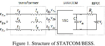
STATCOM based on voltage source inverter and BESS with battery as energy storage constitutes STATCOM/BESS, its three-phase structure is illus-trated as shown in Figure 1.
vEta, vEtb, vEtc is ground voltage of access point; vEa, vEb, vEc is output ground voltage of inverter; lE and rE are respectively inductance and resistance of trans-former; Cdc and vdc are respectively DC capacitance and capacitance voltage; battery model is described
[image:1.516.277.446.416.490.2]with ideal DC voltage source vs and series resistance Rs.
Figure 1. Structure of STATCOM/BESS.
In the steady state process of power system, the ca-pacitance voltage keeps invariant. In the transient process, if capacitance voltage drops, the battery will charge the capacitance and inject power; if capaci-tance voltage overtops, the battery will absorb power from system; if these equal, the battery and power system will not exchange power, which is the physical explanation of damping power system low-frequency oscillation.
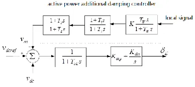
STATCOM/BESS contains active power and reac-tive power controller. The reacreac-tive power controller controls voltage amplitude, the reactive power con-troller controls voltage phase angle, the additional damping controller can be designed on these two con-trollers, and the deliver functions are illustrated in Figures 2 and 3:
The Study of STATCOM-BESS Damping Power
System Oscillations based on DTA Method
Kun Gao1*, Liang Yuan2, Zhenan Zhang1 & Liangzi Li1
1
Henan Electric Power Research Institute, Zhengzhou, Henan, China 2
Henan Electric Power Corporation, Zhengzhou, Henan, China
ABSTRACT: The method of damping torque analysis (DTA) is applied to STATCOM/BESS (Battery Energy Storage System) of multi-machine power system for damping power system low-frequency oscillation. This pa-per investigates how the damping torque of energy storage elements produces, delivers and affects modal damp-ing, and it presents the installation and location of ESS, the selection of additional stable control galley and ad-justing method of parameter allocation based on DTA. The calculation and emulation results indicate that the DTA method could exactly extend the mechanism of EES damping power system oscillations, test the feasibility of adjusting method in ESS, and finally provide the practical example of large-scale power grid.
Keywords: Power System Low-frequency Oscillation (PSLFO); STATCOM; Battery Energy Storage System (BESS); Damping Torque Analysis (DTA)
Figure 2. Control structure of active power.
[image:2.516.299.422.215.307.2]TδE, Kdcp and Kdc1 are active power controller param-eters; K, Tw, T1, T2, T3 and T4 are damping controller parameters; Vdc is capacitance voltage; Vdcref is refer-ence capacitance voltage; δE is phase angle controlling signal; Vds is output active damping controller.
Figure 3. Control structure of reactive power.
TmE, Kvp and Kvp are reactive power controller pa-rameters; K, Tw, T1, T2, T3 and T4 are damping control-ler parameters; V is voltage of insert point; Vref is ref-erence voltage of insert point, mE is amplitude
con-trolling signal; Vvs is output reactive damping control-ler.
The output signals vvs and vds of additional damping controller are named as controlling signal vs. The input signal is named as feedback signal y, which is power deviant of the line.
The ESS equation is linearized and integrated with system state equation and the interface of network algebraic equation, which is deduced to system linear-ization function:
0
s
V
Z Z
21 22 23
31 32 33 3k
0 I 0 0
A A A 0
A A A B
(1)
δ is power angle; ω is rotate speed; Z is status vari-able of generator, containing status varivari-able of storage energy device; B is deliver function of stabilizer from control signal to status variable.
Output variable is indicated as the combination of status variable:
(2)
Ck is the deliver function from status variable to feedback quantity.
The deliver function of damping controller is G(s), so ΔVS= G(s)Δy(3).
Equations(1-3) constitute the system uniform func-tion.
3 DTA IN BESS
3.1 Theory of DTA in BESS
The basic concept of DTA is that stable controller supplies damping torque to power system, which can disclose the production, distribution and delivery of damping torque.
If there are N generators in power system, the structure of deliver function is illustrated as shown in Figure 4:
A22
A21
B3k
A33
A31
A32 A23
∑
∑
I
S WS0I
∆w ∆w
∆a
I S
s V
Z
Figure 4. Transfer framework of damping controller.
The forward channel function from controller signal of damping controller to electromechanical oscillating link is
( ) k s
1
23 33 3k
F A (sI A ) B (4)
Based on linear control theory, the feedback signal y in Equation(2) is an integration of status variables,
( )
j s
is deduced with reconstruction by generator rota-tion speedj:
( ) , 1, 2,
j j
y s j N (5)
The controller supplies damping torque to the os-cillating link of generator j:
Re[ ( ) ( ) ( )] , 1, 2,
Dij j i j i i j
T F
G
j N (6)
Therefore, the additional damping controller of ESS supplies damping to the modal j in power system:
1
Re[ ( )]
N
i ij kj kj k i
j
S H G
(7)Equation (7) indicates that the additional damping controller supplies damping to the oscillating modal by two channels: The controller supplies damping torque to the oscillating modal by first channelHijij, the generator integrated with oscillating modal pro-duces modal damping and damping torque which in-verts into damping modal.
Define D-DTA index: ' T
k q
[image:2.516.65.241.230.301.2]1
( )
DTA
N
i i
ij ij ij j
k i
S S H
G
(8)This index is the sensitivity of modal i to addi-tional damping controller Gk by D-DTA. The de-liver function Gk of controller is quantitatively ad-justed, making modal move into direction that meets demands.
3.2 Setting method of ESS based on DTA
There are three setting items considered in ESS damping low-frequency oscillation: the choice of in-stallation locations, loop election and parameter dis-position. DTA index expresses the effects of ESS on modal. When IDTA is big, it indicates that the sensitiv-ity of ESS to modal damping is big. Therefore, we take IDTA as option standard of installation locations and installation channel.
The phase compensation method is extended to phase setting of controller for parameter disposition. For ESS, this method supplies damping to modal by N channels integrated based on IDTA, which deduces unidirectional channel.
3.3 Certification by homalographic method
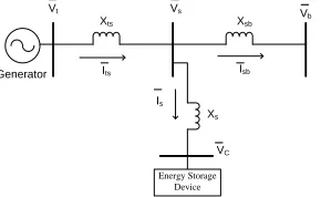
[image:3.516.83.228.371.460.2]The single machine infinite bus with ESS is illustrated in Figure 5:
Figure 5. The single machine infinite bus with ESS.
The ESS could be expressed asV , which is port C voltage of VSC in ESS. The generator voltage is indi-cated in Equation (8):
S sb t ts ts S ts ts
S sb
sb S
C b
S sb S sb ts
X X
V jX I V j(X ) I
X X
X X
V V
X X X X
jX I V
(8)
If the generator is indicated as E’ after transient re-actance X’, it is deduced:
V I X) j(X'
jE' ts (9)
The phasor diagram from Equations (8) and (9) is described in Figure 6:
Figure 6. The phasor diagram.
This figure can be denoted as Equation (9):
ts b c
å å
E' E'
P = Vsinδ' = [bV sinδ + aV sin(δ - γ)]
X' X' (9)
Linearizing Equation (9), the power decination of transmission line is:
control tsdelta
ts ΔP ΔP
ΔP (10)
0
tsdelta b0 0 c0 0 0 tsdelta å
E'
ΔP = [bV cosδ + aV cos(δ - γ )]Δδ = C Δδ
X' (11)
0 0
0 0 0 0 0 0
control c c c
E' E'
P aV sin( ) V aV cos( )
X ' X '
(12)
The second part Pcontrol is variable caused by ESS, which could affect the damping of system oscillation.
ESS can control damping for increasing system os-cillation stability by changing the amplitude Vc and angle γ of output voltage. Supposed damping control using scale-up strategy, the rotation of generator is taken as feedback signal, therefore, we can obtain:
Ddelta damp 0 0 0 c 0 dampV 0 0 0 c 0 control C ] K ) cos( aV ' X ' E K ) sin( aV ' X ' E [ P (13)
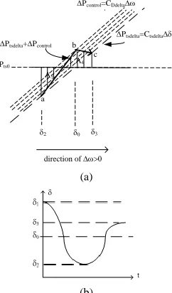
From Equation (11), damping control of ESS could adjust power decination PcontrolCDdelta, which could increase system damping, and the analysis of homalographic method is described in Figures 7 and 8.
In Figure 7, the stability operating point is (0,Pts0) in Pts-δ curve, point a is oscillation initial point. Equa-tion (11) could be indicated as a curve with Ctsdelta rate passing (δ0, Pts0). While moving down 0,
tsdelta P
[image:3.516.56.176.538.593.2] will increase the part PcontrolCDdelta , which makes operating point is lower than Ptsdelta. In Figure 8, the operating point stops at point C, the area ‘aed’ reduces to A1; the area ‘dgf’ increases addition-al area below PtsdeltaCtsdelta; from A2A1,2
' 2 1
is deduced, which explains that the oscillation is suppressed.
In Figure 7, for point C, the acceleration area ‘cdh’ is smaller than A2; because of 0, the
addition-Xts Xsb
Xs
Vt Vs Vb
al part PcontrolCDdelta>0, the operating point is above curve PtsdeltaCtsdeltaas shown in Figure 8; the
acceleration area A3is smaller than ‘cdh’, producing
2 3
, which explains that the oscillation is sup-pressed.
(a)
[image:4.516.52.463.66.103.2](b)
Figure 7. The analysis of damping control in BESS(1).
(a)
[image:4.516.267.455.78.220.2](b)
Figure 8. The analysis of damping control in BESS(2).
4 EXAMPLE
[image:4.516.274.452.152.216.2]4.1 Four-generator two-zone system
Figure 9. Four-generator two-zone system.
There are three oscillation models in the four- genera-tor two-zone system, namely, G1-G2, G3-G4 and G1G2-G3G4. The capacitance of STATCOM/BESS is related to power oscillation variation amplitude. Table 1 indicates the DTA results with additional damping controller, which explains that these two kinds of con-trollers could suppress the oscillation effectively, and the power angle damping controller is better than voltage controller.
4.2 Four-generator two-zone system
Take the operation mode of State Grid Henan Electric Power Company in 2015 for instance, the application of ESS is studied. There are two vital region oscilla-tion modals: Mengjin modal and Yahe modal. The Yahe modal is strong damping modal with 10% damping, which does not need STATCOM/BESS. So Mengjin modal is the only one taken to study the re-straint of power system low-frequency oscillation.
The vital channels of power external transmission are Mengjin to Mudan and Mengjin to Jiyuan. Mudan and Jiyuan are installation places, which are used to check the improvement of dynamic stability of new pattern device.
The comparisons on the results of Mejin modal with and without 100Mvar STATCOM in Jiyuan and Mu-dan are listed in Table 2. The modal damping of Mengjin is raised after installing STATCOM.
Table 2. DTA of ESS in Henan Grid.
Mengjin Modal Modal value Damping Frequence without STATCOM -0.4447+j6.3927 0.0671 1.0194 STATCOM(Mudan) -0.4449+j6.3925 0.0694 1.0174 STATCOM(Jiyuan) -0.4449+j6.3925 0.0694 1.0174
Mengjin modal without STATCOM controller is shown in Figure 10, is Mudan and Jiyuan that are installed with STATCOM are shown in Figure 11 and Figure 12. These curves show that the dedicated STATCOM supplies strong voltage continuously.
Ptsdelta=Ctselta
0
Pts0
direction of 0 A1
A2
2
a
b c
d e
2' f
g
Pcontrol=CDdelta
’
Ptsdelta+Pcontrol h
1
0
1
2
t
0
Pts0
direction of 0 A4 A3
3
2
a b
c
Ptsdelta=Ctsdelta Ptsdelta+Pcontrol
Pcontrol=CDdelta
[image:4.516.84.226.185.389.2]’
Table 1. DTA results with additional damping controller.
Modal Modal value DTA with power angle damping controller DTA with voltage damping controller
[image:4.516.92.213.425.631.2] [image:4.516.262.465.570.613.2]STATCOM/BESS installed in different places impose different depression impacts on oscillation modals. And the changes of modal value of STATCOM realize the depression impacts.
[image:5.516.90.216.248.358.2]Figure 10. Emulation curve of Mengjin modal without STATCOM.
Figure 11. Emulation curve of Mudan installed with STATCOM.
Figure 12. Emulation curve of Jiyuan installed with STATCOM.
5 CONCLUSION
This paper studies the mechanism of ESS damping low-frequency oscillation using DTA, which demon-strates the whole process of ESS supplying damping to modal, and it presents the method of ESS location and parameter disposition based on DTA. What’s more, this paper discovers that the adjustment effect of power outlet side is more remarkable, and the phase angle modulation is better than amplitude modulation. The actual power system indicates that ESS in large-scale network has better application prospect for increasing low-frequency oscillation.
The application of ESS is closely related to capabil-ity, considering the capability in DTA method, the choice of appropriate capability and various oscilla-tion modes. These are key problems of ESS extensive application, which make great research significance in the future.
REFERENCES
[1] Wang M H & Chen H C. 2005. Transient stability con-trol of multi--machine power systems using flywheel energy injection. IEE Proceedings: Generation, Trans-mission and Distribution, 152(5): 589-596.
[2] LIU Feng, MEI Shengwei XIA Deming, et a1. 2004. Nonlinear robust control of SMES to improve the tran-sient stability of power systems. Automation of Electric Power Systems. 28(1): 24-29.
[3] Du Wenjuan & Wang Hangfeng. 2008. Research 011 the principle of energy storage system damping power sys-tem oscillations. Journal of Electric Power Science and Technology, 23(1): 22-27.
[4] Chen Zhong, Du Wenjuan, Wa Ng Haifeng. GAO Shan Power System Low-frequency Oscillations Suppression with Energy Storage System Based OB DTA.
[5] Li Gang, Cheng Shijie. & Wen Jingyu, et a1. 2007. Analysis on the damping characteristics for a power sys-tem with energy storage stability control devices. Auto-mation of Electric Power Systems, 31(17): 1-16. [6] Fei Wanmin, Zhang Yanli & Lu Zhengyu. 2005.
Inves-tigation on the integration of BESS with STATCOM.
Automation of Electric Power Systems, 29(10): 41-44. [7] Han Chong, Li Yah, Yu Jiang, et a1. 2001. Application
[image:5.516.86.219.391.525.2]