Volume 7, Issue 1 (May 2013), PP. 41-47
Damping of Power System Oscillations with STATCOM
Using MATLAB
Anil Kumar Yadav
1, Ravindra Pal Singh
2, Hariom Rathaur
3, Prabhat Kumar
41
K.C.N.I.T, Banda, U.P.T.U., Lucknow U.P.(India) 2
Arya College of Engg. & It,Jaipur, R.T.U. Kota. Reg. (India) 3
K.C.N.I.T,Banda, U.P.T.U., Lucknow U.P. (India) 4
Arya College Of Engg. & It, Jaipur, R.T.U. Kota. Reg. (India)
Abstract:- In power system the low frequency oscillation are inherent due sudden change of load, machine output, faults occurs on the transmission and machine and such frequent occurrence. Satisfactory damping of the power system oscillations therefore is an important issue when dealing with rotor angle (phase angle) stability of the power system. So recently, Flexible AC transmission system (FACTS) controllers have been proposed to enhance the transient or dynamic stability of power system. This report presents the improvement of transient stability of single-machine power system with a STATCOM and anylizing the damping effect of the STATCOM and designing a STATCOM stabilizer to improve power system oscillation stability of single-machine infinite bus system by using „MATLAB‟.
Keywords:- FACTS Devices, MATLAB, POD, STATCOM, Single-Machine connected infinite bus
I. INTRODUCTION
Today, Transmission networks of modern system are becoming increasingly stressed because of growing demand and restrictions on building new lines. One of the consequences of such a stressed system is threat of losing stability following a disturbance. Flexible ac transmission system (FACTS) devices are found to be every effective in stressing a transmission network for better utilization of its existing facilities without sacrificing the desired stability margin. STATCOM, employ the newly technology of power electronic switching devices in electric power transmission systems to control voltage and power flow and play an important role as a stability aid for and transient disturbances in an interconnected power systems. During the last decade, a number of control devices under the terms FACTS technology have been proposed and used. Among all FACTS devices, static synchronous compensators (STATCOM) plays great role in reactive power compensation and voltage support because of its altercative steady state performance and operating characteristics.
The static synchronous compensator (STATCOM) is based on the principle that a voltage-source inverter generates a controlled AC voltage source behind a transformer leakage reactance so that the voltage difference across the reactance produces active and reactive power exchange between the STATCOM and the transmission network. STATCOM has three operating parts: (i) STATIC: based on solid state switching devices with no rotating components, (ii) SYNCHRONOUS: analogous to an ideal synchronous machine with 3 sinusoidal phase voltage at fundamental frequency, (iii) COMPENSATOR: rendered with reactive compensation.
II. SINGLE-MACHINECONNECTEDWITHASTATCOM
The STATCOM is modelled as a voltage source converter behind a step down transformer as shown in
fig.1 the STATCOM generates a controllable AC-voltage so
behind the leakage reactance. The voltage difference between the STATCOM bus AC voltage and V(t) out produces active and reactive power exchange between the STATCOM and the power system.
,
2 sin
1 )
sin (
0
k m c
I J Cos I
c c c
I dt
v d
V c J
Cos V
c V
Loq Lod
DC DC
DC DC
DC DC
K is ratio between A C & D C Voltage m = modulation ratio defined by the PWM. And φ is defined by P W M.
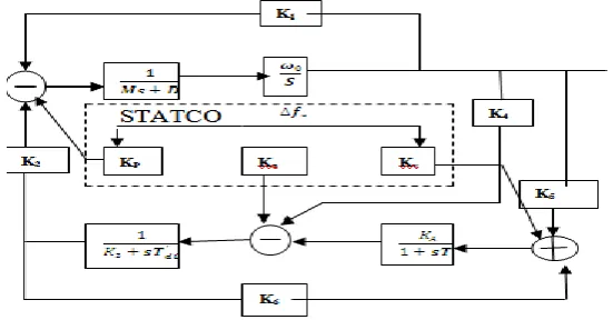
A. PHILIP-HEFFRON MODEL OF STACOM
)
3
(
V
I
JX
V
I
I
x
J
V
V
I
I
I
I
o tL tL t
SDT O L tL
Lo L t LB
) 5 ( ' 1 ' 1 ' 1 1 ' 1 d S DT LB LB S DT LB tL tL B DC S DT LB q S DT LB tLd d S DT LB LB S DT LB tL B DC S DT LB q S DT LB tLd X X X X X X X X Cos V Sin cV X X E X X I X X X X X X X Cos V Sin V c X X E X X I
The Non linear mode of the Power System is
\
(
6
)
1
/
/
0 0 ' '
t t A A fd A fd fd q q e m bV
V
T
K
E
T
E
d
T
E
E
E
m
D
P
P
Where
' '
2
2 ' ' ' ' tLq q tLd d q t tLd d d q q tLq tLd d q tLq q eI
X
I
X
E
V
I
X
X
E
E
I
I
X
X
I
E
P
By linearising eq.5 & 6 it is possible to obtain
t A A fd A fd d fd q q e bV
T
K
E
T
E
T
E
D
E
E
M
D
P
1
/
/
' 0 '
………..(7) Where ……….. (8)……….. (9)
……….. (9)
' 3 1 2 1 1 0 0 0 0 0 do do do b fd q T T k T k M k M D M k E E
fd qE
E
+ C T k k T k k M k T k M k M k V T k k M k M k A V A A VC A q do qc p pc Dc A VDC A qDC PDC 0 0 0 By denoting ,From can obtain
……….(11)
Hence linearising the fourth eq. 1,4 and 11 can obtains
……….. (12)
FIG.2 Phillips-Heffron model of a single-machine infinite-bus power system connected with a STATCOM
III. POWEROSCILLATIONDAMPINGCONTOLLER
The dynamic characteristics of system can be influenced by location of eigenvalues, for a good system response in terms of overshoots/undershoot and settling time, a particular location for system eigenvalues is desired depending upon the operating conditions of the system. The damping power and the synchronizing power are related respectively, to real part and imaginary part of eigenvalue that correspond to incremental change in the deviation of the rotor speed and deviation of rotor angle, power oscillation damping can be improved if real part of eigenvalue associated with mode of oscillation can be shifted to left-side in complex S-plane as desired. This paper presents an STATCOM based POD controller such that the closed loop designed system will have a desired degree of stability. Controller is designed to increase the damping of both the local mode of low frequency power oscillations.
The controller shown has to be analyzed for performance evaluation. This has been attempted on a simple system. The expectation from STATCOM based POD controller is to provide instantaneous solution to power oscillation damping, the settling time as obtain from response of system is expected to be as small as possible. For minimizing settling time real part of eigenvalue corresponding to mode of oscillation are required to be shifted more and more on LHS of complexplane, this will require control effort. There is a hardware limit of any designed controller, for the case of STATCOM, in view of this, the control input parameters m and XSDT should be within their limit and the voltage of the DC link capacitor Vdc should be kept constant
IV. RESULTANDSIMULATIONSOFTWARE
The single machine is running with load. The eigenvalues with STATCOM POD controller at damping constants 1for SMIB system. Amplitude modulation of STATCOM is equal to 1, phase angle of STATCOM is 850C and power factor lagging is 0.85
Table I: Eigenvalues with STATCOM POD controller at D=1 for SMIB system load
controller
Damping Constant = 1 Load decreased
20% (0.8) p.u.
Normal load (1.0) P.u.
Load increased 20% (1.2) p.u. With
STATCOM
-98.8572 -0.2062 + 4.7763i -0.2062 - 4.7763i -0.8866 + 0.5152i -0.8866 - 0.5152i
-98.8556 -0.2165 + 5.4372i -0.2165 - 5.4372i -0.8771 + 0.3266i -0.8771 - 0.3266i
-98.8545 -0.2222 + 6.0218i -0.2222 - 6.0218i -0.8720 + 0.0781i -0.8720 - 0.0781i Without
STATCOM
-98.6815 -0.0660 + 8.0814i -0.0660 - 8.0814i -1.7057 0
-98.6747 -0.0648 + 8.9846i -0.0648 - 8.9846i -1.7148 0
-98.6701-98.6701 -0.0650 + 9.8048i -0.0650 - 9.8048i -1.7190 0 With POD
Controller
-98.8572 -1.0311 + 4.7763i -1.0311 - 4.7763i -1.7731 + 0.5152i -1.7731 - 0.5152i
-98.8556 -1.0826 + 5.4372i -1.0826 - 5.4372i -1.7541 + 0.3266i -1.7541 - 0.3266i
Fig.3.Variation in angular frequency of SMIB system combined response at load=0.8 pu.
With POD Controller
With STATCOM
Without STATCOM
Fig.5.Variation in angular frequency of SMIB system combined response at load=1.2 pu.
V. CONCLUSIONS
In this paper, the power system low frequency oscillations was damped using MATLAB TOOL based POD controller when applied independently with STATCOM and investigated for a SMIB power system. The effectiveness of the proposed controller in damping the low frequency oscillation and hence improving power system stability have been verified thon rough eigenvalues analysis and time domain simulation results with different system conditions under different line loading.
REFERENCES
[1]. WANG, H.F.,and SWIFT, F.J,: „An unified model for the analysis of FACTS devices in damping power system oscillations. Part I: single-machine-bus power system‟, IEEE Trans. Pwr. Deliv., 1997,12,(2),pp. 941-926.
[2]. Modeling STATECOM into power system: H. F. Wang University of both, Bath BA2 7AY,UK. [3]. P.M. Anderson and A.A. Fouad, 1994, Power System Control and Stability, IEEE Press, [4]. Rogers G.; Power System Oscillations, 2000, Kluwer Academic publishers.
[5]. H. F. Wang, July 2000, “A Unified model for the analysis of FACTS devices in damping power system oscillations-Part III: Unified power flow controller,” IEEE Trans. On Power Delivery, vol. 15, no. 3, pp 978-983.
[6]. H.F. Wang, Sept. 1999, “Phillips-Heffron model of power system installed with STATCOM and applications.” IEEEProc.-Geer, Trans. Distr, Vol. 146 No. 5.
[7]. Damping of Power System Oscillation by using co-ordinated tuning of POD and PSS with STATCOM by, A.S.P. Kanojia and B.Dr. V.K. Chandrakar.
Appendix
Parameters of example single-machine infinite-bus power system (in p.u. except indicateded)
System Data : Generator Data:
M=2H, H=3 MJ/MVA,