IJEDR1402160
International Journal of Engineering Development and Research (www.ijedr.org)2286
Influence of Turbulence Generated Air Swirl on
Performance and Emission of SI Engine
1
Mr. Smit K. Mistry,
2Mrs.Vandana Y. Gajjar,
1ME Student, 2Assistant Professor1I.C Engine & Automobile 1
Shree S'ad Vidya Mandal Institute of Technology, Bharuch-392001, Gujarat, INDIA. 1[email protected]
________________________________________________________________________________________________________
Abstract— Turbulence can he pictured as a random motion in three dimensions with vortices of varying size superimposed
on one another, and randomly distributed within the flow. An experimental investigation was carried out to understand the effects on performance and exhaust emissions. For this research work, A Honda single cylinder, 4 stroke, air-cooled, having 2 Brake Horse Power, naturally aspired engine was used. Swirling Device was fitted in intake system of engine. Two Intake system configurations were experimentally checked. The emissions, volumetric efficiency and brake thermal efficiency were also compared by using Swirling Device, with existing intake system. The specific fuel consumption (SFC), volumetric efficiency and exhaust gas emission decreased, whereas brake thermal efficiency (BTE) increase within the test. All experiments were conducted at different load conditions using an electric alternator generator and the exhaust analysis was carried out with the help of multi gas exhaust emission meter. Swirling Device in Existing intake System shows decrease in exhaust emission and fuel consumptions at different load conditions
Index Terms— Swirl, SI Engine, Intake System, Turbulence.
________________________________________________________________________________________________________
I. INTRODUCTION
The uses of automobiles are increasing day by day. Hence efficient petrol engines need encouragement in future since they consume less fuel and significantly reduce polluting gases like carbon monoxide and Unburned Hydrocarbons. Increasing petrol consumption causes large outflow of foreign exchange. Environmental problems have prompted developing countries like India to search for suitable environmental friendly efficient engines or to find methods to reduce emissions from existing engines.
Reductions in fuel consumption can be achieved by a variety of methods, including alternative fuel, Thermal Barrier Coating (TBC ), Turbocharging, reducing friction losses using high grade lubricators. Significant improvements must also be made to the efficiency of the internal combustion I.C engine that powers nearly all the world's vehicle engines. One promising technology for improving IC engine efficiency is modification of intake system to create turbulence. Turbulence increases homogeneity of air-fuel mixture in all strata of combustion chamber.
II. LITERATURE SURVEY
The turbulent flow in a spark ignition engine plays an important role in determining its combustion characteristics and thermal efficiency. In order to analyze the combustion process, the turbulent flow and its turbulence intensity must be studied. To study the turbulent flow as varying various factors in a combustion chamber of a spark ignition engine, the L-head with or without squish area are selected. The turbulent as varying flow on the piston speed, inlet flow velocity, and squish velocity are measured by using hot wire anemometer. To examine the characteristics of turbulent flow, the ensemble averaged mean velocity, turbulence intensity, turbulence intensity decrease ratio, production rate of turbulence intensity, production coefficient of turbulence intensity are analyzed.
Anurag Mani Tripathi, Parth Panchal, Vidhyadhar Chaudhari[7] studied combustion modeling of single cylinder four stroke spark ignition engine having compression ratio of 9.2 and displacement of 124.7 cc using computation fluid dynamics for predicting turbulent flame speed by using premixed combustion model. The methane gas is considered as a fuel in this study. Prediction of turbulent flame speed at different equivalence ratio and engine speed is carried out using FLUENT software. Turbulent flame speed has increased from 7.1053 m/sec to 8.0386 m/sec for equivalence ratio of 0.6 to 1.2. Hence it is concluded that turbulent flame speed increases with increase in equivalence ratio. Turbulent flame speed has increased from 7.1053 m/sec to 8.0386 m/sec for engine speed of 1500 rpm to 3000 rpm. Hence it is concluded that turbulent flame speed increases with increase in engine speed.
IJEDR1402160
International Journal of Engineering Development and Research (www.ijedr.org)2287
with normal turbulence. But it decreases rapidly in the acceleration speed. This happens due to the inability of the swirl adapter to generate swirl at higher wind flow velocity during the higher throttle opening condition. The Brake Specific Fuel Consumption is considerably lower at the lower speed but increases above the normal aspirated graph as the speed goes above 3500 rpm.Kim J.S[17] patented “Fluid Swirling Device” includes a pair of flat planar vanes securely mounted within a cylindrical housing. The vanes have a medial slit extending from the center to a longitudinal end of the vane. The vanes are interconnected at the slits so that they are in criss-cross positioning. The vanes are axially angled so that when positioned in an intake air duct the vanes impart a swirling motion to the air entering the engine providing more complete mixing of the air and fuel. These devices utilize vanes which are radially curved to attach both ends of the vanes to the same side of the cylindrical housing. However, the vane portions which are at the central area produce higher stresses at the attachment points due to the effects of leverage. In addition, the absence of a secure central connection and thereby lack of rigidity of the vanes at the central area results in deflection movement in response to the forces of the fluid flow. The movement of the vanes may adversely affect the fluid flow movement by setting up harmonics in the fluid.
Norbert G. Lyssy[18] patented “Fixed Blade Turbulence Generator” is device and method for installing a device for improving the fuel/air mixture in internal combustion engines with or without a fuel injection system. An intermediate member operatively dispositioned between the engine intake manifold and the intake port comprises at least two helically twisted blades attached to the inner bore of an intake port opening in the intermediate member; these blades are angled in relation to the fuel/air flow path and twisted so as to impart a swirling to the fuel/air mixture. In fuel injected systems, the swirl is imparted to the air flow just prior to encountering the umbrella mist injected to the intake port by the fuel injector. The swirl mixing of the fuel/air improves engine performance, reduces pollutants, and increases gas mileage. Further, in fuel injection systems, the device reduces or eliminates the common occurrence of a burned intake valve caused by a clogged injector.
Kuang-Hsiung Lo and Su-Lin[19] patented “Air Swirling Device”, which comprising a pipe member connected in between an air cleaner and an internal combustion engine. A plurality of swirl flow ducts spirally formed in the pipe member about an axis defined at a longitudinal center of the pipe member. A central flow duct axially formed in the pipe member and surrounded by the plurality of swirl flow ducts. Whereby upon suction by the engine, the inlet air flow will be swirled as guided by the plurality of swirl flow ducts to form a plurality of streams of swirling air flow to be combined with a central air flow through the central flow duct to form a forced-draft air how to enter the engine. This swirling flow motion gives better mixing of air and fuel in combustion chamber.
Heru Prasanta Wijaya[20] patented “The air-stirring blade” is provided that comprises a cy1indrical body whose mid portion is provided with blade of such a construction that the inner side of the blade takes the form of stirred grooves with dip angle of about 10° to 80° or typically 30° with respect to vertical axis of the body. The outer side of the blade is of the same shape with the inner side thereof and there are four tangent lines between the blade and body forming a channel of cap-shaped cross section which is twisted along the body.
III. EXPERIMENTAL SETUP
The schematic diagram of experimental set up of 4-stroke SI engine is shown in Fig 1
Constant Speed Variable load engine testing method was used in experimental analysis. SI Engine was coupled with eddy dynamometer. There are various other measuring devices used in experimental analysis. Fluid-Expansion Temperature Measurement Devices, Techo meter, Multimeter, Air-Flow meter, Exhaust Gas Analyzer, etc were used to measure various parameters like temperature, engine speed (r.p.m), volt and current from dynamometer, Volume of intake air flow, exhaust emissions respectively.
Engine Specifications
No of cylinder 1
Engine Hp 2 BHP (1.49 KW)
Displacement 79.6 cc
Cooling Air Cooled Engine
IJEDR1402160
International Journal of Engineering Development and Research (www.ijedr.org)2288
Experiments were done on various loads starting from no load to partial load and partial load to full load ranges. Constant engine speed was maintained during experiments. Speed of engine was maintained 2800.IV. RESULT & DISCUSSION
Table I Result Table having Original Intake configuration
Sr. No. Brake Power (kW) Brake Thermal Effi. (%) Indicated Thermal Effi. (%) Vol. Effi. (%)
1 0.377 8.071 15.562 60.138
2 0.438 9.077 16.330 61.036
3 0.534 10.578 17.507 61.933
4 0.657 12.035 18.446 63.729
5 0.754 12.654 18.525 64.626
6 0.876 13.351 18.662 65.524
7 0.970 12.382 16.850 66.421
8 1.037 11.706 15.656 67.319
Table II Result Table having Swirling Device in Intake Manifold
Sr. No. Brake Power (kW) Brake Thermal Effi. (%) Indicated Thermal Effi. (%) Vol. Effi. (%)
1 0.377 8.560 14.915 59.241
2 0.438 9.428 15.455 59.241
3 0.534 11.171 17.025 60.138
4 0.657 13.066 18.610 61.036
5 0.754 14.189 19.456 62.831
6 0.876 15.290 20.177 63.729
7 0.970 13.698 17.652 64.626
8 1.037 13.177 16.734 64.626
As shown in above tables, following results were obtained from experimental analysis. Various graphs were plotted as given below at various brake power ranges.
GRAPHS
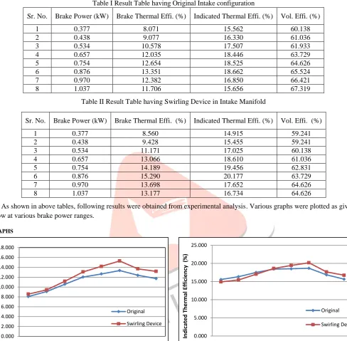
Fig 2 Brake Thermal efficiency VS Brake Power Fig 3 Indicated Thermal efficiency VS Brake Power Fig 2 shows the relation between brake power and Brake Thermal Efficiency. As the brake power increases the Brake Thermal Efficiency also increases up to certain rated load and then decrease above that operating point. During the calculations and plotting graph Brake Thermal Efficiency on various loads was found higher while swirling device is attached in intake manifold of the system. Maximum increment in Brake Thermal Efficiency was found while operating engine in part load to full load range. Maximum percentage increase in Brake Thermal Efficiency obtained is 14.52 % at 0.876 kW brake power.
Fig 3 shows the relation between brake power and Indicated Thermal Efficiency. As the brake power increases the Indicated Thermal Efficiency also increases. During the calculations and plotting graph Indicated Thermal Efficiency on various loads was found lower and also higher while swirling device is attached in intake manifold of the system. Maximum increment in Indicated Thermal Efficiency was found while operating engine in part load to full load range. Maximum percentage increase in Indicated Thermal Efficiency obtained is 8.12 % at 0.876 kW brake power.
0.000 2.000 4.000 6.000 8.000 10.000 12.000 14.000 16.000 18.000
0.377 0.438 0.534 0.660 0.754 0.876 0.970 1.037
R rake Th e rmal E ff ic ie n cy ( % ) B.P (kW) Original Swirling Device 0.000 5.000 10.000 15.000 20.000 25.000
0.377 0.438 0.534 0.657 0.754 0.876 0.970 1.037
Ind ic at e d Th e rm al Effic ie nc y ( %)
B.P (kW)
Original
IJEDR1402160
International Journal of Engineering Development and Research (www.ijedr.org)2289
Fig 4 Volumetric efficiency versus Brake Power Fig 5 Carbon Monoxide versus Brake PowerFig 4 shows the relation between brake power and Volumetric Efficiency. As the brake power increases the Volumetric Efficiency also increases. During the calculations and plotting graph Volumetric Efficiency on various loads was found lower while swirling device is attached in intake manifold of the system. Maximum reduction in Volumetric Efficiency was found while operating engine in part load to full load range. Maximum percentage decrease in Volumetric Efficiency obtained is 4.00 % at 1.037 kW brake power.
Fig 5 shows carbon monoxide emissions at different brake powers. As brake power increases carbon monoxide emissions also increase. Incompleteness of combustion is main reason for carbon monoxide emissions. While plotting graph, carbon monoxide emissions on various loads were found lower while swirling device is attached in intake manifold of the system. Maximum reduction in carbon monoxide emissions were found while operating engine in part load to full load range. Maximum percentage decrease in carbon monoxide emissions obtained is 16.90 % at 0.876 kW brake power.
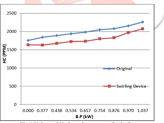
Fig 6 Unburned Hydrocarbons versus Brake Power
Fig 6 shows unburned hydrocarbon emissions at different brake powers. As brake power increases unburned hydrocarbon emissions also increase. Incompleteness of combustion is main reason for unburned hydrocarbon emissions. While plotting graph, unburned hydrocarbon emissions on various loads were found lower while swirling device is attached in intake manifold of the system. Maximum reduction in carbon monoxide emissions were found while operating engine in part load range. Maximum percentage decrease in unburned hydrocarbon emissions obtained is 12.01% at 0.876 kW brake power.
V. CONCLUSION
An experimental study was conducted to evaluate various performance and emissions parameters of original configuration intake manifold and swirling device attached to intake manifold of engine According to the results of experiments, Swirling device in intake manifold of engine has overall positive impact on performance and emission parameters. Maximum percentage decrease in Specific Fuel Consumption was 12.72 % at rated power with swirling device attached to intake manifold. Maximum percentage increase in Brake Thermal Efficiency was 14.52 % at rated power with swirling device attached to intake manifold. Maximum percentage increase in Indicated Thermal Efficiency obtained is 8.12 % at rated brake power with swirling device attached to intake manifold. Volumetric efficiency decrease, as there is obstruction to flow due to swirling device attached to intake manifold. But
54 56 58 60 62 64 66 68
0.377 0.438 0.534 0.657 0.754 0.876 0.970 1.037
ŋ
vol
(%)
B.P (kW)
Original
Swirling Device 0 0.5 1 1.5 2 2.5 3
0.000 0.377 0.438 0.534 0.657 0.754 0.876 0.970 1.037
C
O
%
B.P (kW)
Original
Swirling Device
0 500 1000 1500 2000 2500
0.000 0.377 0.438 0.534 0.657 0.754 0.876 0.970 1.037
H
C
(P
P
M
)
B.P (kW)
Original
IJEDR1402160
International Journal of Engineering Development and Research (www.ijedr.org)2290
maximum percentage decrease in Volumetric Efficiency obtained is 4.00 % at full brake power. Carbon monoxide and unburned hydrocarbon emissions are reduced in large amount. Maximum percentage decrease is 16.90 % and 12.01 % respectively. So, from above findings, it is concluded this Swirling Device improves performance and emission of SI engine.ACKNOWLEDGMENT
The author would like to thank SVMIT Mechanical engineering department, Bharuch for their valuable input during course of investigation.
REFERENCES
[1]C. Ramesh Kumar And G. Nagarajan “Investigation Of Flow During Intake Stroke Of A Single Cylinder Internal Combustion Engine” ARPN Journal of Engineering and Applied Sciences Vol. 7, February 2012, pp. 180-186
[2]Sung Bin Han, Yon Jong Chung and Songyol Lee “Effect of Engine Variables on the Turbulent Flow of a Spark Ignition Engine” KSME Journal, Vol. 9, No.4, 1995 pp. 492-501
[3]S. A. Sulaiman, S. H. M. Murad, I. Ibrahim And Z. A. Abdul Karim “Study Of Flow In Air-Intake System For A Single-Cylinder Go-Kart Engine” International Journal Of Automotive And Mechanical Engineering , Volume 1, Pp. 91-104, January-June 2010
[4]Z. Barbouchi and J. Bessrour “Turbulence study in the internal combustion engine” Journal of Engineering and Technology Research Vol.1 (9), pp. 194-202, December, 2009
[5]Wendy H.K ,Kamaruzzaman Sopian, Zulkifli“ CFD Investigation of Fluid Flow and Turbulence Field Characteristics in a Four-Stroke Automotive Direct Injection Engine ” The Institution of Engineers, Malaysia (Vol. 69, No.1, March 2008
[6]Stanislav Beroun, Pavel Brabec, Václav Dvořák “Compression Chamber Of An Si Engine With The Increasing Of The Turbulence” Research Centre of Engine and Automotive Engineering Liberec. 2006
[7]Anurag Mani Tripathi, Parth Panchal, Vidhyadhar Chaudhari “ Turbulent Flame Speed Prediction For S.I. Engine Using Methane As Fuel” International Journal of Engineering Research and Applications Vol. 3(4), Jul-Aug 2013, pp.248-254 [8]B.Murali Krishna and J.M.Mallikarjuna “Effect of Engine Speed on In-Cylinder Tumble Flows in a Motored Internal
Combustion Engine” Journal of Applied Fluid Mechanics, Vol. 4, No. 1, pp. 1-14, 2011.
[9]A.K.M.Mohiuddin “Investigation of the swirl effect on engine using designed swirl adapter” IIUM Engineering Journal, Special Issue, Mechanical Engineering, 2011 pp 197-205
[10]Kihyung Lee, Choongsik Bae, Kernyong Kang “The effects of tumble and swirl flows on flame propagation in a four-valve S.I. engine” Applied Thermal Engineering 27 (2007) pp. 2122–2130
[11]Kern Y. Kang And Je H. Baek “Turbulence Characteristics Of Tumble Flow In A Four-Valve Engine” Experimental Thermal And Fluid Science 18 (1998) Pp. 231-243
[12]Turbulence Article - http://www.sciencedaily.com/articles/t/turbulence.htm [13]Internal Combustion Engines by R.K.Rajput Pg. No 201
[14]Internal Combustion Engine Fundamentals by J.B.Heywood Pg No 307-339 [15]Introduction To Internal Combustion Engines By Richard Stone Pg No 300-340
[16]Engineering Fundamentals of the Internal Combustion Engine by Willard W. Pulkrabek Pg No 206-213 [17]Kim JS. Fluid swirling device, in United States Patent, USA Patent No-7,028,663 B1 2006
[18]Lyssy NG. Fixed blade turbulence generator, United States Patent-US 4359997 B1, 1982
[19]Kuang-hsiung Lo,Su-Lin, Air swirling device, United States Patent-US 20070169764 A1, 2007