Remote Laboratory for a Servomotor Control
System with Embedded Architecture
M.F.Mollon1, E.H.Kaneko2, L.Niro3, A.R.M.Feitosa4, M.A.F.Montezuma5
Graduated Student, Federal University of Technology – Paraná, Cornélio Procópio, Paraná, Brazil1,2
Substitute Professor, Federal University of Technology – Paraná, Cornélio Procópio, Paraná, Brazil3
Professor, Federal University of Technology – Paraná, Cornélio Procópio, Paraná, Brazil4,5
ABSTRACT: In this paper we present the development of a remote laboratory (RL) for a servomotor control system.
The RL is embedded on the single board computer BeagleBone Black (BBB) with an interface for performing remote experiments and storing the experimental data. In addition, the Proportional-Integral-Derivative (PID) controller used to control the servomotor is embedded in the PIC32MX795F512L microcontroller made by Microchip. A TFT display is attached to the control system as a local configuration and test interface. For communication with the control interfaces, protocols were assembled using Universal Asynchronous Receiver/Transmitter (UART) communication. Finally, the servomotor system and the control interfaces are evaluated through experimentation, resulting in a satisfactory operation of the PID controller through the control interfaces.
KEYWORDS:Remote Laboratories, Control Systems, Embedded Systems, Web Development.
I.INTRODUCTION
The teaching of new theories and concepts to students in universities is traditionally carried out in classrooms. Areas within the engineering curriculum, such as electrical circuits and electronics [1], experimental physics [2] and control engineering [3], have their learning complemented through experimentation in laboratories. Practices in laboratory are important because they enhance the understanding of concepts and develop critical thinking. For areas such as control engineering the teaching of new models and theoretical ideas are important, especially if they can be verified through experimentation [4, 5, 6].
In universities, the integration of new pedagogical methodologies to engineering education, such as the complementation of traditional teaching through online tools, is fundamental. Among the tools available on the Internet,there are the Learning Management Systems (LMS) and the Web labs, which are divided into virtual and remote laboratories [4, 7]. The LMS, such as Moodle, support administrative activities of those responsible for the system, as well as allow the release of documented information and monitoring of student activities [4,8]. Virtual labs currently have interactive graphical interfaces and perform computational simulations of mathematical models and physical processes. Remote Laboratories (RLs) use real plants and physical devices and have their processes controlled remotely through a graphical interface [7, 4].
As seen in [9] the control engineering community, represented by different universities, gathers efforts for the development of RLs, thus proving their importance in teaching methodology. The RL has advantages for the teaching of control engineering, such as the more realistic and dynamic perspective and the learning of a real control process [5]. Although useful for engineering education, RLs need real control systems in execution [4]. An example of an experiment available in RLs for control engineering is one that involves real-time closed-loop control systems, as seen in [3, 4, 7, 9, 10].
strategy is used by the Proportional-Integral-Derivative (PID) controller, which is one of the most common tools for controlling systems, being widely used in several industrial applications related to the control of hydraulic, mechanical and thermal processes, in addition to be a fundamental controller in control systems involving motors [11, 12]. The implementation of the controller can be done in several systems e.g. computers, Programmable Logic Controllers (PLCs), Field Programmable Gate Array (FPGAs) and embedded systems [11,12].
II.SCOPE OF RESEARCH
In this work, a RL was developed for a control system with a closed loop control in real time. Initially a bibliographical research, presented in section III, was carried out to determine the state of the art of RLs applied in the area of control engineering, this research allowed to define the development stages of the work. The first step, presented in section IV, was the definition of the architecture for the RL showing an overview of the integration of all concepts and technologies present in the work. The second step, described in section V, was the definition of the experiment, as a servomotor’s speed control, and the control system development. The third step, presented in section VI, was the development of a protocol for standardizing the serial communication between the control plant and the RL server. The fourth step, presented in section VII, was the construction of the web application that provides access to a control plant as a RL.
The fifth step, presented in section VIII, was the development of a local control interface, through a TFT display, allowing to execute control experiments in direct contact with the control system. The TFT display is a type of touchscreen display used in industry for control and automation of systems allowing to control and oversee complex operations through a graphical interface [13,14,15]. The use of this technology adds to this project the ability to check problems directly in the control plant. The results and discussions, in section IX, present the experimental design validation based on the definition of a test scenario, in which a square wave was applied as setpoint and the controller gains were determined empirically. In this context, the experiment was performed by the RL interface and validated by the local interface. As results, the controller presented satisfactory performance, since it corresponded to the defined setpoint and there was no saturation of the same. In addition, this experiment confirmed the correct integration of the control interfaces due to the absence of failures during the execution of the process.
III.SURVEY OF REMOTE LABORATORIES FOR CONTROL ENGINEERING
RL that control closed-loop processes in real-time must have good performance and adaptability regarding the continuity of the interaction between the control interface and the process located remotely. Thus, the client-server architecture presents itself as a good approach for creating RLs, since it has great flexibility, performance and adaptability in situations where quality of service and continuity of communication are fundamental [3]. RLs with the client-server architecture are presented in [3, 9, 10, 16, 17]. In recent RL approaches, the client-server architecture has evolved into a three-tiered architecture. In this approach, amiddleware layer is responsible for dealing with the communication between client and server, reducing the dependence between them [7]. The use of three-tiered architecture in RLs can be seen in [4, 7]. In the traditional architecture of the RLs the server runs on a desktop computer that is connected to the control plant by means of specific hardware for data acquisition, as can be seen in [3, 7, 9, 10, 17]. An alternative to the computer with the data acquisition board is the use of a single-board computer i.e. a complete computer available on a single printed circuit board e.g. Raspberry Pi and BeagleBone Black (BBB), as seen in [4, 16].
seen in [3, 9, 10, 16, 17]. In the second approach, the control algorithm is found on the client side and the control loop closes through the network in a transparent way to the user, as can be seen in [4, 7, 18]. These two approaches suffer from delays in the communication network between client and server in different ways. In the first approach, there is no delay in the process control of the plant, but there is a delay in interaction and process monitoring by the user. In the second approach, there is no delay in user interaction, but the control process may lose performance [9].
In more recent work such as [4, 7] it is possible to perceive the emergence of a better organization of the way the RLs are implemented, approaching a standardization of Web laboratories development. In [19] this standardization is presented as the smart device paradigm and appears as an extension of the definition of the smart devices that make up the Internet of Things (IoT). This paradigm when applied to the traditional client-server architecture implies a greater autonomy of server actions. In this way client and server are fully decoupled, the server will provide access to the RL functionality through a service, organized as an Application Programming Interface (API). The independence of the client allows it to be both web and mobile applications, deconstructed in components responsible for accessing different features of the API made available by the server. Since Web laboratories are available on the Internet, client-server communication makes use of Hypertext Transfer Protocol (HTTP) and WebSockets, which is an efficient and bidirectional way of performing the continuous data transmission required by a RL [19].
IV.ARCHITECTURE FOR THE REMOTE LABORATORY
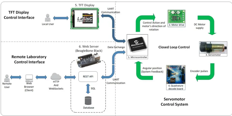
Figure 1 shows the complete architecture of the RL, which is the main contribution of this work, containing the overview of the integration among all technologies used.
Figure 1:Architecture for the remote laboratory.
It is important to highlight the main differences of the architecture developed in this work:
The architecture used is the traditional client-server, but the servomotor control algorithm does not run on the same hardware as the server application. The RL’s web application server is embedded in the BBB, while the control algorithm is embedded in the microcontroller present in the control plant;
The architecture has a local access point, available from a graphical application running on a TFT display;
The exchange of information between the microcontroller in the control plant and the different interfaces uses the same protocol that standardizes UART serial communication.
V.SERVOMOTOR CONTROL SYSTEM
The servomotor’s speed control experiment uses a closed loop control technique with the PID controller. According to [20], the PID controller is composed of three terms: Proportional, Integral and Derivative. Each one corresponds to a mathematical operation with the error function (the difference between setpoint and system response) and the sum of these terms results in the control action (u) as shown in Equation (1).
( ) = ( ) + ( ) + ( ) (1)
wherein:
, , – proportional, integral and derivative gains; ( ) – error function.
The behaviour of proportional term is the same as an amplifier with adjustable gain whereas the integral term is responsible to eliminate the steady state error and make sure that the system's output agrees with the setpoint. The derivative term enhances the closed loop stability and allows prediction of future error [20, 21].However, Equation (1) presents the classical PID representation in continuous time, where some operations with integral and derivative terms are required to calculate the control action, but they cannot be solved directly by the microcontroller. Therefore, to be possible this calculation it is necessary to approximate these operations by differences equations. This process is called controller digitalization. In this project we used the Euler method (backward differences) to approximate the derivative term and also the Tustin method (trapezoid rule) to approximate the integral term in Equation (1). Equation (2) shows the digital PID controller implemented in the microcontroller [20, 22].
( ) = ( ) + + + ( )
2 +
( )− ( )
(2)
wherein:
KP – Proportional Gain; Ki – Integral Gain; Kd – Derivative Gain;
ia(Tp) – Integral action (previous instant); e(Tp) – Previous instant error;
e(Tc) – Current instant error; T – sample time;
u(t) – control action.
Hewlett Packard (HP). The servomotor’s speed was calculated using the encoder and a quadrature decoding board (4), which works with Serial Peripheral Interface (SPI) bus. The Pololu Motor Drive MC33887 (2) which allows the motor’s direction change, is powered by a 14.8 V LiPo battery as well as motor.
VI.SERIAL COMMUNICATION PROTOCOLS
The serial communication protocols standardize the data exchange between the control interfaces and the servomotor control system, made through UART serial communication. There are five communication protocols developed, each one responsible for specific functionalities of the control system.Table 1 presents the general structure of the protocols.
Start Byte (SB)
Data Bytes (DB)
End Byte (EB)
Table 1:General structure of the serial communication protocols.
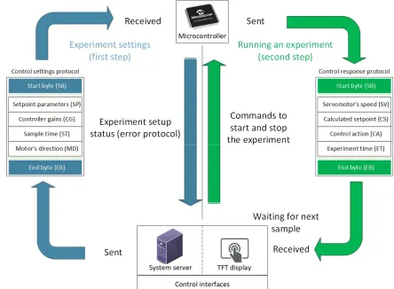
According to Table 1, the protocols have two delimiters of their contents, which are the Start Byte (SB), responsible for indicating the beginning of the data transmission and the End Byte (EB) representing the ending of the data transmission. These bytes also identify the types of protocols handled by the system. The number of Data Bytes (DB) depends on the type of protocol. Figure 4 shows the two main protocols developed, "control settings" and "control response", including their interaction with the system.
The sending of “control settings protocol” from control interfaces to the microcontroller is the first step to running an experiment. The content of this protocol is chosen by the user, according to the parameters shown in Figure 4. When these data is received by the microcontroller, the control parameters are validated and the “error protocol” is returned to the control interface to notify that the configuration was successful or if there are any errors in the parameters. In this way, if there are no errors and the command to start the experiment is sent, the second step is executed, in which according to the sample time, the microcontroller sends a sample by the “control response protocol” to the interface that is running the experiment. This process is done periodically until the command to stop the experiment is sent to PIC32 or the experiment time achieves its maximum value of 1 minute. In addition, the control system has the "system configuration protocol" that allows the choice of control interface (display or remote) that will perform the experiment. This protocol is unique to the TFT display due to its purpose of system configuration and control system testing. Finally, the "control query protocol", allows querying in the microcontroller the configured parameters for an experiment.
VII.WEB APPLICATION FOR REMOTE LABORATORY
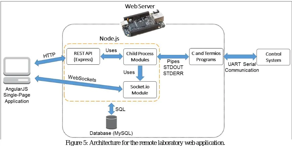
Figure 5 shows the architecture for the RL’s web application and the integration between the used software technologies.
Figure 5: Architecture for the remote laboratory web application.
The RL web application allows the user to perform an experiment in control engineering through a set of features. The user can configure and query the parameters of interest to control the system, visualize the evolution of the control by means of graphs updating at run time, start and stop control of the system and export data from previously performed control experiments. All RL features are executed by BBB, which makes them available through an API organized according to the architectural style REpresentational State Transfer (REST) and built in the Node.js JavaScript language environment through the Express framework. Each API functionality executes programs built with the C language and the Termios library to perform serial communication with the control system through the communication protocols defined in section VI.
establish a WebSocket between client and server, this communication channel is unique for the server to perform the streamingof the control system monitoring data. The database is used for the persistence of the data from control experiments. The client interface is a single-page application built with the AngularJS framework, the entire interaction of the AngularJS application with the API is performed by asynchronous HTTP requests.The web application of the remote laboratory also has a set of functionalities aimed at the management and control of the users’ access to the system.
VIII.TFT DISPLAYLOCAL INTERFACE FOR CONTROL PLANT
Considering the TFT display interface (5) presented in Figure 1, it is composed of a Mikromedia for PIC32 display from MikroEletronika. The main purpose of this interface is to configure and test the system i.e.it is possible to activate or deactivate the communication with the remote interface and to see if it is running an experiment or not. In addition, it is also possible to run experiments through the display interface to verify the correct operation of the control system.
IX.RESULTS AND DISCUSSION
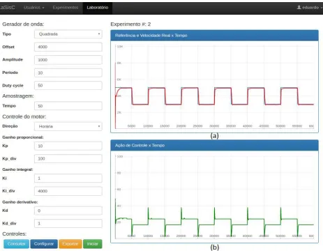
An experiment was performed to evaluate the control system and the control interfaces behaviour. Therefore, a random control scenario presented in Table 2 and an empirical method were used to tune the PID gains. The values for these gains and their divisors are: 1/10 for Kp, 1/4,000 for Ki and 0/1 for Kd. The control scenario and the gains were shown in the remote interface in Figure 7.
Parameter Value
Wave type Square
Offset 4,000 RPM
Amplitude 1,000 RPM
Period 10s
Duty-cycle 50%
Sample time 50 ms
Direction of rotation Clockwise Table 2: Random control scenario.
The Figures 6 and 7 present, respectively for the TFT display and remote interface, the system responses for the experiment performed with the configurations of Table 2 and the PID gains. In Figures 6a and 7a the actual speed of the servomotor is shown in red colourand the reference speed is indicated in yellow for the TFT display and blue for the remote interface. In this context, the control achieved satisfactory results, since the speed of the servomotor corresponded to the desired setpoint. Furthermore, there is no controller saturation, since the maximum value applied through the motor drive is 50 % of the maximum allowed as shown in the Figures 6b and 7b to TFT display and remote interface, respectively.
Figure 6: TFT Display experiment. (a) Speed response (RPM) x Time(s); (b) Control action response (%) x Time (s).
X.CONCLUSION
This paper presented the development of a remote laboratory for a servomotor control system with PID controller. Its main contributions are the development of a fully embedded client-server architecture, in which the web application server is embedded on the single board computer the BeagleBone Black through a Linux distribution. The servomotor control system has the digital PID controller implemented in a PIC32 microcontroller. In addition, the control system features a TFT display as a local interface for system configuration and testing, and specific communication protocols were developed for integration between the control system and the TFT display and RL interfaces.
Finally, the controller developed and the integration between the system and the control interfaces were evaluated experimentally. The controller obtained satisfactory results, since it corresponded to the setpoint provided by the square wave and no controller saturation was found. As the experiments performed by the interfaces presented similar results, then they were correctly integrated to the control system through the developed communication protocols.
REFERENCES
[1] A. V. Fidalgo et al.,“Adapting remote labs to learning scenarios: Case studies using visir and remotelectlab,” IEEE Revista Iberoamericana de Tecnologias del Aprendizaje, vol. 9, no. 1, pp. 33–39, 2014.
[2] J. P. S. Simão et al.,“Remote labs in developing countries an experience in brazilian public education,” in Proc. IEEE GHTC 2014, pp. 99– 105, 2014.
[3] H. Vargas et al.,“A systematic two-layer approach to develop web-based experimentation environments for control engineering education,” Intelligent Automation & Soft Computing, Taylor & Francis, vol. 14, no. 4, pp. 505–524, 2008.
[4] J. Sáenz et al.,“Open and low-cost virtual and remote labs on control engineering,” IEEEAccess, vol. 3, pp. 805–814, 2015.
[5] C. M. Ionescu et al.,“A remote laboratory as an innovative educational tool for practicing control engineering concepts,” IEEE Transactions on Education, vol. 56, no. 4, pp. 436–442, 2013.
[6] T. Karakasidis, “Virtual and remote labs in higher education distance learning of physical and engineering sciences,” in Proc. IEEE EDUCON 2013, pp. 798–807, 2013.
[7] J. Chacón et al.,“Ejs, jil server, and labview: An architecture for rapid development of remote labs,” IEEE Transactions on Learning Technologies, vol. 8, no. 4, pp. 393–401, 2015.
[8] R. K. Ellis, “Field guide to learning management systems,” ASTD Learning Circuits, pp. 1-8,2009.
[9] H. Vargas et al.,“A network of automatic control web-based laboratories,” IEEE Transactionson Learning Technologies, vol. 4, no. 3, pp. 197– 208, 2011.
[10] H. Vargas et al., “Web-enabled remote scientific environments,” Computing in Science Engineering,vol. 11, no. 3, pp. 36–46, 2009. [11] K. J. Åström, T. Hägglund,“Advanced pid control,” Research TrianglePark (USA): International Society of Automation, 2006.
[12] W. L. Torres, I. B. Q. Araujo, J. B. M. Filho, A. G. C. Junior, “Mathematical modeling and pid controller parameter tuning in a didactic thermal plant,” IEEE Latin America Transactions, vol. 15, no. 7, pp. 1250-1256, 2017.
[13] M. R. Bhalla, A. V. Bhalla, “Comparative study of various touchscreen technologies,” International Journal of Computer Applications, vol. 6, no. 8, pp. 12-18, 2010.
[14] J. Y. Ruan, P. C. P. Chao, W. D. Chen, “A multi-touch interface circuit for a large-sized capacitive touch panel,” IEEE Sensors, Kona, HI, pp. 309-314, 2010.
[15] W. Liu, R. Liu, P. Yu, L. Feng, X. Guo, “Device/circuit mixed-mode simulations for analysis and design of projected-capacitive touch sensors,” Journal of Display Technology, vol. 11, no. 2, pp. 204-208, 2015.
[16] J. Bermúdez-Ortega et al.,“Remote web-based control laboratory for mobiledevices based on ejss, raspberry pi and node.js,” IFAC-PapersOnLine, vol. 48,no. 29, pp. 158 – 163, 2015.
[17] G. Farias et al., “Developing networked control labs: A matlab and easy java simulations approach,” IEEE Transactions on Industrial Electronics, vol. 57, no. 10, pp. 3266-3275, 2010.
[18] M. Guinaldo, J. Sánchez, S. Dormido, “Diseño de un sistema de control anticipativo basado en paquetes para control en red,” in Proc. CISCI ’10, 2010.
[19] C. Salzmann, D. Gillet, “Smart device paradigm, standardization for online labs,” in Proc.IEEE EDUCON 2013,pp.1217–1221, 2013. [20] K. J. Åström, T. Hägglund, “PID controllers: theory, design, and tuning,” Research Triangle Park, NC: International Society of Automation,
vol. 2, 1995.
[21] K. Ogata,“Modern control engineering,” Upper Saddle River, N.J: Prentice Hall, 2010.