Biometric Person Identification from 3D Ear
Images and a Time Efficient Ear Shape
Recognition
Jeena Maria Daniel1, Sherin Mariam Thomas2
PG Student [Signal Processing], Dept. of ECE, College of Engineering, Kallooppara, Kerala, India1 Assistant Professor, Dept. of ECE, College of Engineering, Kallooppara, Kerala, India2
ABSTRACT: Biometric identification methods have proven to be more natural, efficient and easy for users than traditional methods of human identification. However, current growth trends in different biometrics applications present challenges to researchers. Therefore, to overcome these challenges, we need to make the recognition process time efficient. The proposed system is primarily responsible for automatic 3D ear segmentation, shape determination and person identification from DTCWT based feature extraction.Based on the geometrical feature values from the segmented ear region, ear shape can be in oval, round, rectangular, and triangular categories. We used indexing technique with balanced split (k-dimensional (KD) tree) data structures to categorize the database separately. This paper also aims in feature vector extraction by DTCWT method;thereby making ear identification more accurate.
KEYWORDS: Ear Biometrics, Dual Tree Complex Wavelet Transform (DTCWT), KD Tree
I.INTRODUCTION
The term “Biometrics” is associated with the use of certain physiological or behavioral characteristics to authenticate or identify an individual. Now-a-days various biometric techniques are available like finger print, face, DNA, iris, finger vein, voice, etc. Of these the latest technology is “Ear Biometrics”. In recent years, the ear has gained much popularity among various physiological biometric traits, as it has been found to be a reliable biometrics for human recognition. Ear is found to be very stable. Studies have shown that major changes in the ear shape happen only before the age of 8 years and after that of 70 years. Ear is remarkably consistent and does not change its shape under facial expressions like face. Color distribution of the ear is almost uniform. Ear biometrics comes under passive biometrics and does not need much user cooperation.The proposed system is primarily responsible for automatic 3D ear segmentation, shape determination and person identification from DTCWT based feature extraction. This paper also represents hierarchical categorization of the 3D ear database using the shape information and surface depth information, respectively. Based on the geometrical feature values from the segmented ear region, ear shape can be in oval, round, rectangular, and triangular categories. We used indexing technique with balanced split (k-dimensional (KD) tree) data structures to categorize the database separately. This paper also aims in feature vector extraction by DTCWT method along with surface shape and curvedness value; thereby making ear identification more accurate.
This paper represents 3D ear segmentation and shape classification from the reduced gallery. Two stages of our approach are training phase and testing phase .Firstly, we select the profile face image. From face image ear region is segmented and from this segmented ear region we obtain the shape of the ear. Ear shape can be circular, rectangular, elliptical and triangular. After that 3D feature extraction is performed. On the testing phase, we compare the query image from the reduced set of gallery images and the shape is determined.
II.LITERATURE SURVEY
computation and thresholding since there is a sharp step edge around the ear boundary, then we do image dilation and connected-component analysis to find the potential regions containing ears. Next for every potential region, we grow the region and find the region with minimum dissimilarity between the histogram of shape indexes with the model template. Finally among all of the regions, we choose the one with the minimum dissimilarity as the detected region containing ear. They get 91.5 percent correct detection with a 2.5 percent false alarm rate. No recognition results are reported based on this detection method[4].
Chen and Bhanu proposed “Contour Matching for 3D Ear Recognition”. In this, ICP algorithm is to match a data shape to a model shape by iteratively minimizing the distance between corresponding pairs. In the training phase, the helixes of model ears in 3D images are extracted and saved. In the testing phase, the helix of the test ear in 3D image is detected. For each model ear helix, we run the ICP algorithm to find the initial rigid transformation which aligns a model ear helix with the test ear helix. After this, we have a set of rigid transformations for each model-test pair. Then by applying the initial rigid transformation obtained previously to selected control points of the model ear, we run ICP to improve the transformation which brings model ear and test ear into best alignment, for every model-test pair. The root mean square (RMS) registration error is used as the matching error criterion. The model ear with the minimum RMS error is declared as the recognized ear [5].
Umarani Jayaraman, Surya Prakash, and Phalguni Gupta proposed “Indexing Multimodal Biometric Databases Using Kd-Tree with Feature Level Fusion”. This paper proposes an efficient indexing technique that can be used in an identification system with large multimodal biometric databases. The proposed technique is based on Kd-tree with feature level fusion which uses the multi- dimensional feature vector. A multi-dimensional feature vector of each trait is first normalized and then, it is projected to a lower dimensional feature space. The reduced dimensional feature vectors are fused at feature level and the fused feature vectors are used to index the database by forming Kd-tree. The proposed method reduces the data retrieval time along with possible error rates. [19].
Hasan Demirel and Gholamreza Anbarjafari [22] DWT technique is for interpolating the images. But the images obtain from DWT and IDWT technique is not sharper compare to previous technique and comparatively low PSNR.
III.PROPOSED METHOD
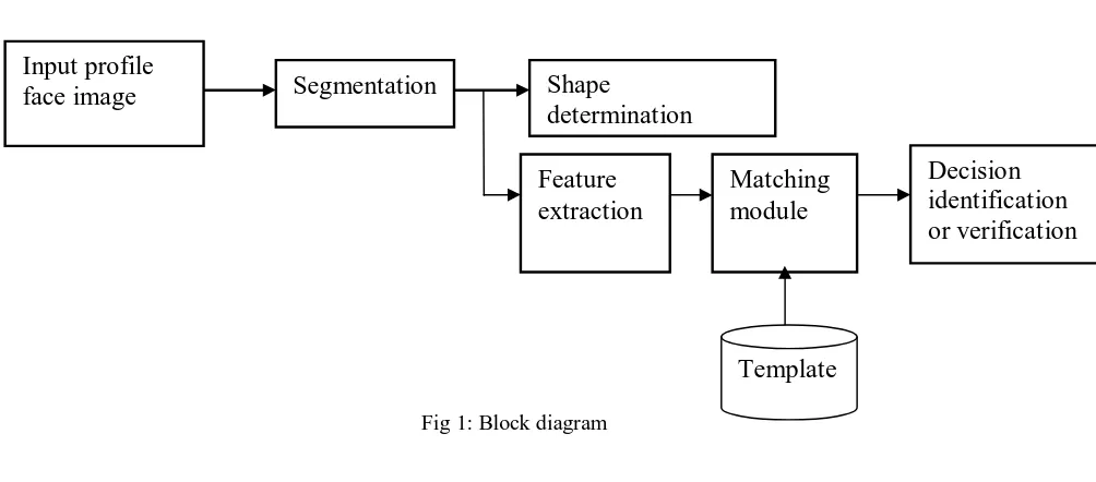
Fig 1: Block diagram
a) SEGMENTATION
Image segmentation is the process of partitioning a digital image into multiple segments (sets of pixels, also known as super pixels). The goal of segmentation is to simplify and/or change the representation of an image into
Input profile
face image
Segmentation
Shape
determination
Matching
module
Feature
extraction
Decision
identification
or verification
something that is more meaningful and easier to analyze.The main problem with ear segmentation is occlusion because of long hair, over the ear headphones, ear rings or other objects. In this paper we aim to segment only ear region pixels other than bounding box detection. This will help to extract features that only represent ear region and hence we can minimize the errors. In this algorithm first we take a side face image of an individual. Then creates the color transformation structure from RGB to LAB and apply it to the test image. The input is RGB which consists of three layers, Red, Green, and Blue. The output is LAB which consists of L*, a*, and b* layers. L* represents brightness and has range from 0 to 100. a* represents degree of rednessgreenish, having range from -100 to -100. (Positive values for redness, and negative values for greenish). b* represents degree of yellowish-bluish and has the same ranges as a*. This technique is adaptable for different skin colors and various lighting conditions. Since RGB representation of color images is not suitable for characterizing skin-color, it first converts the RGB
color space to chromatic color space, and then uses the chromatic color information for further processing. In RGB
color space, the triple components (R, G & B) represent not only color but also luminance which may vary across a person’s face due to the ambient lighting and is not a reliable measure in separating skin from non-skin regions. Luminance can be removed from the color representation in the chromatic color space. Then we apply threshold to the resultant image and convert to binary.The cropped ear images may be of varying sizes and so the feature set of images may also vary. Hence the images are normalized to a constant size by resizing technique (Bilinear method). If two images are of different sizes, e.g. one is of size (x‟, y‟) and the other is of size (x”, y”), then the two images
are mapped to a constant size.
b) SHAPE BASED CATEGORIZATION
If good and reliable image segmentation is available, a popular approach to object classification is based on analysing the shape of the extracted regions. Many shape descriptors have been proposed such as eccentricity, Euler number, compactness, convexity, etc… Generally, one of the aims when developing a shape descriptor is to make it invariant to certain transformations or variations. One approach to shape representation is to define a set of standard shapes such as rectangles, ellipse, triangular, etc… In addition to Iannarellis work on ear classification, Choars et al. categorized ears based on their shape. We adapt the categories proposed by Iannarelli, i.e., round, rectangular, triangular, and oval. To categorize 3D ears into the different shape categories shown in Fig.2, moments are computed from the binary mask of the ear obtained after ear region segmentation. Moments or central moments are used as quantitative measures for shape description. The translation, rotation, and scale invariant shape indexes such as circularity, rectangularity, triangularity, and ellipticity are computed from the moments and their values lie within the range (0,1].
Fig. 2: Iannarellis classification based on the shape of ear helix.
For a given shape, S, the circularity measure is defined as follows [6].
)
(
)
(
)
(
2
1
2 , 0 0 , 2 2 0 , 0s
s
s
C
irs
(7)where μ refers to the general two-dimensional (p+q)th ordermoments of a density distribution function ρ(x, y)
defined as
dxdy
y
x
s q p qp,
where (x, y) represent the coordinates of the binary objectρ(x, y), and
C
irsranges over [0, 1]. For a circle, the ratioresults 2 0 , 0 2 , 0 0 , 2)
(
)
(
)
(
s
s
s
into 1/2π . Hence, for a perfect circle thevalue
C
irswill peak at 1. To overcome the sensitivity of the orientation between the rectangle and region of interest, a normalized rectangularity measurement proposed by Rosin is defined as follows [8]B
D
R
ct
D
1
Re
(9)where R is the difference between the rectangle and the region of interest, D is the difference between the region of interest and the rectangle, B is the area of the rectangle, and
Re
ct
Dranges over [0, 1].The measures of ellipticity and triangularity are proposed by Rosin. Affine transformation of a circle result into an ellipse, and the affine moment invariants of a circle can be represented as [7]
4 0 , 0 2 1 , 1 2 , 0 0 , 2 1
)
(
)
(
)
(
)
(
s
s
s
s
I
(10)where μ is described in equation 8, and ρ(x, y) is the characteristics function of the binary object whose ellipticity to be measured. For a unit radius circle, the value of
I
1 is 216
1
.The measure of ellipticity is defined as follows [7]1 2
1
16
I
Elp
; if 1 216
1
I
= 2 1
16
1
I
; otherwise (11)The triangularity measure proposed is as follows [7]
1
Tri
= 108I
1,ifI
1≤108
1
= 1108
1
I
, otherwise; (12)If training ear images of a single subject are not classified in the same shape category, we label it as overlap between the shape categories in which the ears are distributed. The most overlap is found between rectangular and oval shaped ears and between triangular and round shaped ears. The goal of the proposed approach is to categorize the 3D ear gallery for quick retrieval. Thus, for a specific subject if there is such an overlap during enrollment, we store the data of that subject in each of the overlapped shape categories. This ensures that during recognition we do not misclassify a subject that have a shape measure that falls between two categories.
c) DTCWT FEATURE EXTRACTION
Approximate shift invariance, good directional selectivity in 2-dimensions,perfect reconstruction and limited redundancy.
The DT-CWT is used to implement 2D wavelet transforms where each wavelet is oriented, and useful for image processing such as image denoising and enhancement applications.Ear analysis using DWT provides singularities (edges) in only three directions (0, 45, 90) and without phase information which is improved by finding the singularities, with phase information, in six directions (0,+/-15, +/-30, +/-45, +/-60, +/- 75, 90) and at many freq bands using DT-CWT to achieve shift invariant features for better accuracy and efficiency at less computational cost as compared to existing methods.
d) CATEGORIZATION THROUGH INDEXING
In recent years, increasing numbers of computer applications in CAD, geography, biology, medical imaging, etc., access data stored on large databases. A common feature to such databases is that objects are described by vectors of numeric values, known as feature vectors, which map individual instances to points in a high dimensional vector space. The effect of indexing is to split the database to create an abstract ordering of the data points. There are two different paradigms to split a feature space, one is balanced and the other is unbalanced. Both methods have their advantages and disadvantages. The indexing algorithms that use balanced split data structures are computationally inexpensive compared to indexing algorithms that use unbalanced split data structures.
i) KD Tree
KD treeis a space-partitioning data structure for organizing points in a k-dimensional space. KD trees are a useful data structure for several applications, such as searches involving a multidimensional search key (e.g. range searches and nearest neighbour searches). KD trees are a special case of binary space partitioning trees. The KD tree is a binary tree in which every node is a k-dimensional point. Every non-leaf node can be thought of as implicitly generating a splitting hyperplane that divides the space into two parts, known as half-spaces. Points to the left of this hyperplane are represented by the left subtree of that node and points right of the hyperplane are represented by the right subtree. We selected the KD tree, which is a balanced split data structure to index a database. KD trees are abstractions of binary search trees for higher dimensional databases. Unlike R-trees, R*-trees and X-R*-trees, KD R*-trees have no overlap between nodes. A KD tree is formed by a recursive sub-division of the feature space using a (D − 1) dimensional hyper-plane at every node, where D is the dimension of the feature space. While indexing, at first, the feature space is recursively split across the top log2n dimensions. This results in a tree structure of depth log2n. After the formation of the KD tree, range search is performed using the feature vector computed from the query 3D ear image. The range query retrieves the list of the gallery images which belong to the hyper rectangle that includes the query. This list of gallery images are labelled as reduced gallery.
e) MATCHING MODULE
Energy, Entropy, Mean and Standard Deviation of each sub-band of DT-CWT is calculated to create a feature vector. Generally, Euclidian distance and Canbera distance as given by equation (13) and (14) are used as similarity measures for matching the feature vectors of the test image with that of the images stored in database(1:N) match. Euclidian Distance
( , ) = ∑ ( − ) (13) Canbera Distance
( , ) =∑ | |
| | | | (14)
In this proposed approach, minimum distance is taken for matching the test image with the template images stored and thereby obtained the output image.
IV.RESULT AND DISCUSSION
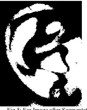
Fig 4: Test Image Fig 5 shows the segmented ear image by Lab colour space transformation.
Fig 5: Ear Image after Segmentation
Fig 6 shows the identified output from the training set. Both input and output are similar which means the person gets identified from the training set.
Fig 7 shows the shape determined output obtained in MATLAB.
Fig 7: Shape Determined Output
V. CONCLUSION
This paper presents a system for automatic 3D ear segmentation and time-efficient recognition. Here LAB colour space is used to segment the ear region from the 3D profile images. The segmented 3D earregion is used for shape determination and feature extraction. Dual tree complex wavelet transform based feature extraction is performed. Energy, Entropy, Mean and Standard Deviation of each sub-band of DT-CWT is calculated to create a feature vector. Euclidian distance is used as similarity measures for matching the feature vectors of the test image with that of the images stored in database(1:N) match. Indexing technique with balanced split data structure are to categorize the database. This method is faster than other3D ear recognition systems in the literature.Future extensions of this work will include the use of categorization for every modality in multi modal biometrics along with fusion at the decision level. This has its application in biometrics- person identification.
REFERENCES
[1] Sayan Maity and Mohamed Abdel-Mottaleb, “3D Ear Segmentation and Classification Through Indexing”,IEEE Transactions On Information Forensics And Security, Vol. 10, No. 2, February 2015
[2]A. Abaza, A. Ross, C. Hebert, M. A. F. Harrison, and M. S. Nixon,“A survey on ear biometrics,” ACM Comput. Surv., vol. 45, no. 2, 2013,
Art. ID 22.
[3] A. V. Iannarelli, “Ear Identification” ”,IEEE Transactions OnForensic Identification, Paramont Pub., Vol 5,No 7 May 1989.
[4] H. Chen and B. Bhanu, “Human ear detection from 3D side face range images,” in 3D Imaging for Safety and Security, vol. 35. Berlin, Germany: Springer-Verlag, 2007, pp. 133–155.
[5] H. Chen and B. Bhanu, “Contour matching for 3D ear recognition,” in Proc. 7th IEEE Workshops Appl. Comput. Vis., vol. 1. Jan. 2005, pp.
123–128.
[6] J. Žuni´c, K. Hirota, and P. L. Rosin, “A Hu moment invariant as a shape circularity measure,” Pattern Recognit., vol. 43, no. 1, pp. 47–57,
2010.
[7] P. Rosin, “Measuring shape: Ellipticity, rectangularity, and triangularity,” Mach. Vis. Appl., vol. 14, no. 3, pp. 172–184, 2003.
[8] P. L. Rosin, “Measuring rectangularity,” Mach. Vis. Appl., vol. 11, no. 4, pp. 191–196, 1999.
[9] H. Freeman and R. Shapira, “Determining the minimum-area encasing rectangle for an arbitrary closed curve,” Commun. ACM, vol. 18, no.
7, pp. 409–413, 1975.
[10] M. J. Fonseca and J. A. Jorge, “Indexing high-dimensional data for content-based retrieval in large databases,” in Proc. 8th Int. Conf.Database Syst. Adv. Appl., 2003, pp. 267–274.
[11]Ping Yan and Kevin W. Bowyer, “Biometric Recognition Using 3D Ear Shape” IEEE Transactions on pattern analysis and machine intelligence, vol. 29, no. 8, August 2007.
[12] Mayuri D Patil,Shivkumar S Tomar,Setu K Chaturvedi,”Dual Tree Complex Wavelet Transform (DTCWT) based Adaptive Interpolation
Technique for Enhancement of Image Resolution”,International Journal of Computer Applications,Volume 80 – No 14, October 2013
[13] Ramesha K, K B Raja,”Dual Transform based Feature Extraction for Face Recognition”, International Journal of Computer Science Issues, Vol. 8, Issue 5, No 2, September 2011
[14] Hasan Demirel and Gholamreza Anbarjafari,”Discrete Wavelet Transform-Based Satellite Image Resolution Enhancement”, IEEE Trans. geoscience and remote sensing letters,vol.49,no.6, June 2011.
BIOGRAPHY
Jeena Maria Daniel is currently pursuing M.Tech in electronics with specialisation in Signal Processing from College Of Engineering, Kallooppara (CUSAT University), Kerala, India. She received her B.Tech degree in Electronics and Communication from Musaliar College of Engineering and Technology, Pathanamthitta (MG University), Kerala, India. Her areas of interest are Digital Image Processing, Biometrics, Digital Communication, Wavelet and Embedded Design.