Parameter Calculation of PV Module by
Simulation and Computation
Umesh P.Pagrut1, A. S. Sindekar2
M Tech Scholar, Department of Electrical Engineering, Govt. College of Engineering, Amravati, India1 Associate Professor & Head, Department of Electrical Engineering, Govt. College of Engineering, Amravati, India2 ABSTRACT: The photovoltaic module is typically represented by an equivalent circuit whose parameters are calculated using the experimental current-voltage (I-V) characteristic. The precise determination of these parameters remains a challenge for researchers, which led to adiversification in models and numerical methods used for its computation. In the present study the model has been studied by two mathematical methods. One method of computation is based on simulated Newton-Raphson iteration method and another is computation (mathematical) method. Newton-Raphson iteration method is solved by MATLAB simulation. Two diode model with series and parallel resistance is considered for the calculation of five parameters of selected module 125Wp/12V/SN80. Parametric calculation of Io ,Ipv, Rs, Rsh and A is the objective of this work. The simulation results for the 125Wp/12V
SN80moduleareconfronted withthoseofthemanufacturer and to the computation method.
KEYWORDS:PV array, simulation, irradiance, saturation current, photovoltaic current
I.INTRODUCTION
Energy demand is increasing in the world at fast rate. To cope up with increased demand, newer methods of energy production are being implemented. Renewable energy sources are the prime one in these technologies. Solar power and wind power are capturing the world highly as compared to other form of energy sources.
Renewable energy sources are preferred due to its non-pollutant qualities, compared to fossils fuels. Solar energy is one of the best available promising renewable power source, among the available renewable energy sources. Solar energy is getting more popularity with its characteristics advantages such as easy erection and instant generation. Again it is getting more popularity due to the benefits provided by Government.
The major constituent of solar system is its panels, which is the transforming source of sunrays power into electrical power. Panels are the costly items in the components of solar system. So the accurate design of panel is essential for its optimum use, before its installation. This can be done by simulation technique. The simulation requires the PV cell modeling which confirm thenonlinear current-voltage (I-V) and power-voltage (P-V) characteristics of solar cell.
There are various PV cell modules studied by researchers in the literature. One of the simplest is one diode model. [1] In broad sense this model is derived by three parameters: Short Circuit Current (Isc), Open Circuit Voltage
(Voc), and Diode Ideality Factor (A). When the parameter series resistance (Rs) is added in this model, the accuracy of
model gets improved. One drawback of this model is that it is not capable of temperature (T) variation handling. Parameter shunt resistance (Rsh) significantly improves the model efficiency. [2] This model is having a drawback of
reduced accuracy under low irradiance (G) level, especially at open circuit voltage (Voc). Additional diode design is
added to the model for the recombination loss in the depletion region of the cell of solar module. [3] This is two diode model. This model has more parameters to calculate. This model gives more accuracy because this model is more practical especially under low voltages.
Vol. 5, Issue 4, April 2016
For explaining a photovoltaic model, drawing equivalent circuit is the basic method. Its parameters are calculated from the knowledge of current-voltage (I-V) characteristics. It is typical task to determine accurate values of parameters. In order to get accurate results, various numerical methods are used for the model. In this paper attempt is made to calculate five parameters of model. MATLAB simulation is carried for the module 125Wp/12V/SN80. The results are confronted with data sheet provided by manufacturer. Conclusions are drawn by tallying the results of the mathematical methods adopted.
NOMENCLATURE
Id DiodeCurrent, Ampere
Is DiodeSaturation Current, Ampere
Iph Photocurrent, Ampere
Io Reverse Saturation Current, Ampere
q Electron Charge, 1.60217646*10-19 C
k BoltzmannConstant, 1.3806503*10-23J/K
T CellTemperature, Kelvin
A DiodeFactor
Rs SeriesResistance, Ohm
Rsh ShuntResistance, Ohm
N NumberofCellsin Series Voc OpenCircuit Voltage, Volt
Isc ShortCircuit Current, Amp
Vmpp Voltageatthe Pointof Max .Power, Volt
Impp Currentatthe Pointof Max. Power, Amp
Ipv Output Current, Amp
Ish Shunt Current, Amp
Vpv Output Voltage, Volt
G Solar Irradiation, Watt/ Meter2
Lot of work is done by researchers, on the mathematical methods of parameter calculation. SabanYilmazet al.
[5] presented the double diode model with the help of MATLAB for the characteristics of solar radiation (G) at 1000 w/m2 and temperature (T) 25oC. Dominique Bonkoungouet al. [6] studied the single and double diode model for five parameters. The parameters are compared between datasheet values and values obtained from Newton-Raphson iteration method. Aneek Islam et al. [7] presented the two diode model characteristics for parameter calculation by efficient iteration method. The characteristics curves obtained are matched with data sheet of manufacturer. T. Skocil et al. [8] presented the two diode cell mathematical modeling.
II.MODELLING OF PHOTOVOLTAIC MODULE
(a) I-V Curve at T = 25oC, G= 1000w/m2
(b) P-V Curve at T = 25oC, G= 1000w/m2
Fig.1: Simulated Characteristics of PV Module 125Wp/12V/SN80
The nonlinear nature of PV systems is apparent from Fig.1. The nonlinear characteristics of PV module 125Wp/12V/SN80 indicate that array current and power depends on the array terminal operating voltage. [11]
Below is given the step by step approach for the design of two diode model, two diodes (D1, D2) connected in
parallel, resistance connected in series (Rs) and resistance connected in parallel (Rsh). This is the general mathematical
model developed by considering the split up of current by Kirchhoff’s law. This mathematical model can be applied to any two diode PV module for study purpose.
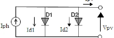
The first model is the ‘Two Diode Ideal Model’ in which two diodes D1 and D2 are connected in parallel. This
model is shown in the Fig. 2. The next model is ‘Two Diode Model with Series Resistance’, in which resistance (Rs) is
connected in series towards output side. This model is shown in the Fig. 3. Next model is ‘Two Diode Model with Series and Shunt Resistance’, in which series resistance (Rs) and shunt resistance (Rsh) is connected in series and
parallel respectively at output side. This model is shown in the Fig. 4.
1. Two Diode Ideal Model:
Two diodes PV cell equivalent circuit is shown in Fig 2. This is the ideal model of two diodes. It represents the simplest form of model. In this model five parameters can be calculated. Along the five parameters, first two parameters are saturation current Is1, Is2 for the diode D1 and diode D2 respectively. Third and fourth parameter is
ideality factor A1 and A2 of first diode D1 and second diode D2respectively. Fifth parameter is photovoltaic current Iph.
The ideality factor A1 and A2 are the functions of voltage across the devices. At high voltage, when the recombination
in the device is dominated by the surfaces and the bulk regions, the ideality factor is close to one. However at lower voltages, recombination in the junction dominates and the ideality factor approaches to two. The junction
0 2 4 6 8 10 12 14 16 18 20 0
1 2 3 4 5 6 7 8
I-V Curve
Voltage V (Volts)
C
u
rr
e
n
t
I
(A
m
p
e
re
)
0 2 4 6 8 10 12 14 16 18 20 0
20 40 60 80 100 120 140
P-V Curve
Voltage V (Volts)
P
o
w
e
r
P
(
W
a
tt
s
Vol. 5, Issue 4, April 2016
recombination is modeled by adding a second diode D2 in parallel with the first diode D1 and setting the ideality factor
A2 typically to two.
Fig. 2: Circuit Diagram for Two Diode Ideal Model
Theory of Kirchhoff’s law is used to derive characteristic equation of this model.
Ipv = Iph – Id1 – Id2 …………. (1)
Current of first diode is
= {exp ∗
∗ ∗ −1}…………. (2)
Current of second diode is
= {exp ∗
∗ ∗ −1}…………. (3)
Output current Ipv is given by following equation
= − exp ∗
1∗ ∗ −1 − exp
∗
2∗ ∗ −1
…….. (4)
Equations (2), (3) and (4) give the diode current Id1, Id2 and output current Ipv. Ideality factor for diode D1 is one and for
diode D2 is two. For the same PN junction temperature (T) and irradiance (G), the short circuit current (Isc) is having
highest value, which is generated by PV cell. At the same time, open circuit voltage (Voc) is having highest value at the
PV cell terminals. [12] [13] It is given by Isc = Ipv = Iph for Vpv = 0.
2. Two Diode Model with Series Resistance:
Model with resistanceconnected in series (Rs) is shown in Fig. 3, in two diode model. Here six parameters are to
determine. Along these six parameters, first two are saturation currents Is1 and Is2 flowing from the diodes D1 and
D2respectively. The two diodes D1 and D2 are connected in parallel having saturation current Is1 and Is2, two
idealityfactor for two diodes A1 and A2, photo current Iph generated by current source, which is dependent on the solar
radiation (G) and the series resistance (Rs).
Fig. 3:Circuit Diagram for Two Diode Model with Series Resistance
According to Kirchhoff’s law, output current (Ipv) is given by
Ipv = Iph – Id1 – Id2…….. (5)
Current from first diode D1,
= exp ( ∗ )
∗ ∗ −1 ……….. (6)
Current from second diode D2,
= exp ( ∗ )
∗ ∗ −1 ……... (7)
= − exp ( ∗ )
∗ ∗ −1 − exp
( ∗ )
∗ ∗ −1 …….. (8)
Output power is given as,
= ∗ ………. (9)
= { − exp ( ∗ )
∗ ∗ −1 − exp
( ∗ )
∗ ∗ −1 }…….. (10)
Equation No. 6 and 7 give the diode current Id1 and Id2 for diode D1 and diode D2 respectively. Output current Ipv is
given by equation No. 8.
3. Two Diode Model with Series and Shunt Resistance:
Two diode model comprising resistance connected in series (Rs) and shuntresistance (Rsh)connected in parallel is
shown in Fig. 4. Two diodes D1 and D2are connected in parallel, having saturation current Is1 and Is2, and having the
diode factor A1 and A2 respectively, Photocurrent (Iph) generated by current source which is dependent on solar
radiation (G). Resistance(Rs) is connected in series and resistance (Rsh) is connected in parallel.
Fig. 4:Circuit Diagram for Two Diode Model with Series and Shunt Resistance
According to Kirchhoff’s law, output current (Ipv)is given by,
= − − − ….. (11)
Current from first diode D1,
= exp ( ∗ )
∗ ∗ −1 ….. (12)
Current from second diode D2,
= exp ( ∗ )
∗ ∗ −1 …….. (13)
The shunt current is given by
=
∗ ….. (14)Output current (Ipv) of the solar cell with double diode D1and diode D2 with series Rs and shunt Rshresistance is given
as,
= − exp ( + ∗ )
1∗ ∗ −1
− exp ( + ∗ )
2∗ ∗ −1 −
+ ∗
…….. (15) The output power P is given by,
= ∗ …….. (16)
= ∗{ − exp ( + ∗ )
1∗ ∗ −1
− exp ( + ∗ )
2∗ ∗ −1 −
+ ∗
}
Vol. 5, Issue 4, April 2016
Equation No. 12 and 13 give the saturation current Is1 and Is2 from the diode D1 and diode D2 respectively. Current Ish
flowing from the shunt resistance Rsh is given by the Equation No. 14. The output current Ipv is given by the Equation
No. 15.
III.COMPUTATION METHOD TO DETERMINE UNKNOWN PARAMETER
In most cases for specific values of series (Rs) and shunt (Rsh) resistance, the major impact of parasitic resistance is to
reduce the fill factor.[14] Both the magnitude and impact of series (Rs) and shunt (Rsh) resistance depend on the
structure of the solar cell, at the operating point of the solar cell.[15] So, necessary approach for accurate determination of parameters is done.The five parameters Ipv, Io, A, Rs, Rsh for the model with series (Rs) and shunt (Rsh)resistance, are
obtained simultaneously by solving the equations in MATLAB using the iterative method like Newton-Raphson iteration method, which solve system of nonlinear equations. And again all these five parameters are calculated by mathematical equations derived from the two diode model connected with series (Rs) and shunt (Rsh)resistance. For
notational convenience, the following equations can be defined,
Rso = where V = Voc …….. (18)
Rsho = where I = Isc…….. (19)
Where,
Rso =Series resistance at the standard temperature condition i.e. 25 oC.
Rsho = Shunt resistance at the standard temperature condition i.e. 25 oC.
V = Output voltage of two diode model with series and shunt resistance. I = Output current of two diode model with series and shunt resistance. Rso and Rsho can be obtained experimentally from the I-V curves.
Thermal voltage (Vt) of a PV module having Ns cells connected in series is given by the formula
Vt = ∗ ∗ Volt, …………. . (20)
where k is Boltzman constant, q is electron charge, T is the temperature of PN junction. [6]
Five parameters Rsh, Io,Ipv, A and Rs are calculated from following equations.
Shunt resistance (Rsh) is given by the following equations
Rsh = Rsho…….. (21)
Rsh= ∗
∗ ∗∗ Ohm….. (22)
Reverse saturation current (Io) is given by,
Io = Isc− exp −
∗ …….. (23)
Output current (Ipv) is given by,
= ∗ 1 +
ℎ +
∗
∗ −1
……… (24) Diode ideality factor (A) is given by,
A =
∗ ……… (25)
−
= - Io * 1− ∗ ∗∗ −
(1 -
∗ ) …………. (26)Table No. 1: Data Sheet of Selected PV Module 125Wp/12V/SN80
IV.SIMULATED AND COMPUTATIONAL RESULTS
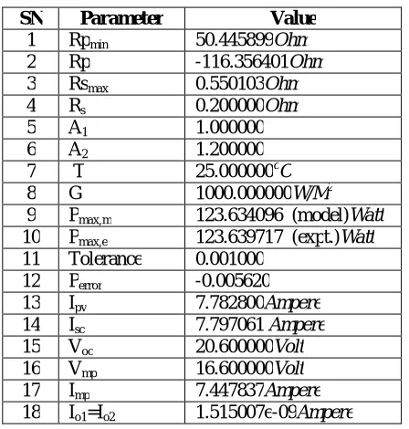
Following are the resultsobtained bysimulated Newton-Raphsoniteration method for the PV module 125Wp/12V/SN80.
Part A:Results by Simulation
SN Parameter Value 1 Rpmin 50.445899Ohm
2 Rp -116.356401Ohm
3 Rsmax 0.550103Ohm
4 Rs 0.200000Ohm
5 A1 1.000000
6 A2 1.200000
7 T 25.000000oC
8 G 1000.000000W/M2
9 Pmax,m 123.634096 (model)Watt
10 Pmax,e 123.639717 (expt.)Watt
11 Tolerance 0.001000 12 Perror -0.005620
13 Ipv 7.782800Ampere
14 Isc 7.797061 Ampere
15 Voc 20.600000Volt
16 Vmp 16.600000Volt
17 Imp 7.447837Ampere
18 Io1=Io2 1.515007e-09Ampere
SN Description Details
1 Operator SGTIPDC
2 Product ID 125WP/12V
SN80 3 Current Temp Coefficient
(mA/oC)
2.000
4 Voltage Temp Coefficient (mV/oC)
-2.0000
5 Model Area (cm2) 9620.00
6 Sensor TemperatureoC 28.7
7 Irradiance (mW/cm2) 0.0992
8 Isc(A) 7.7828
9 Voc(V) 20.6813
10 Pmp(W) 123.6398
11 Imp(A) 7.4577
12 Vmp(V) 16.5788
13 Fill Factor 76.81
14 Module Efficiency (%) 12.96
15 Estimated Shunt Resistance (Ohm)
29.4783
16 Estimated Series Resistance (Ohm)
Vol. 5, Issue 4, April 2016
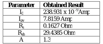
Following are the resultsobtained by computation (mathematical) for the PV module 125Wp/12V/SN80.
Part B:Results by Computational Method
Parameter Obtained Result I0 238.931 x 10 -9Amp
Ipv 7.8159 Amp
Rs 0.1627 Ohm
Rsh 29.4385 Ohm
A 1.3
V. COMPARISON OF PARAMETRIC VALUES
Table No. 2: Comparative Chart for Results ofPVModule 125Wp/12V/SN80
Parameter Actual Data of
PV Module
By Simulation
By Computation
I0 --- 1.515007
e-09 Amp
238.931 x 10 -9Amp Ipv --- 7.782800
Amp
7.8159 Amp
Rs 0.1252
Ohm
0.550103 Ohm
0.1627 Ohm
Rsh 29.4783
Ohm
50.445899 Ohm
29.4385 Ohm
A --- 1.2 1.3
Table No. 2 shows the comparison of parametric values obtained by Newton-Raphson iteration method, used for solving nonlinear equations of PV module 125Wp/12V/SN80 and by computation, for the five parameters Ipv, Io, A, Rs
and Rsh. This set of parameter is compared with original manufacturer data. It is seen that values of shunt resistance
(Rsh) and series resistance (Rs)are well matched with the manufacturer data and by computation method.
VI.CONCLUSION
The model for five parameter I0, Ipv, Rs, Rsh and A is presented and parameters are obtained by computation and
simulation methods. Simulation technique is used to draw the open circuit I-V and P-V characteristics of PV module125Wp/12V/SN80. The result obtainedby Newton-Raphson iteration method of solving nonlinear equations of PV module in MATLAB simulink and parameters computed are compared with manufacturers data.
Based on the methods used for parameter determination i.e. simulation and computation, and the results obtained by these two techniques, when compared with manufacturer data pertaining to these parameters, following broad conclusion can be drawn:
1. Computation by mathematical method requires long time as compared to simulation method.
2. As simulation method is based on computer programming, it requires software which is costly means. 3. Very less time is required for obtaining results by simulation than computation.
4. Simulation is having its own limitations for obtaining results, due to designing consideration of programming. 5. Certain constants are to be strictly assumed for computation of results mathematically.
6. There is slight deviation in some results obtained by simulation and computation, compared to manufacturers data, due to assumptions considered for the respective method.
REFERENCES
[3] Tan Y. T., Kirschen D. S., and Jenkins N., ‘A Model of PV Generation Suitable for Stability Analysis’, IEEE Trans. Energy Converts, Vol. 19, No. 4, pp. 748-755, 2004.
[4]KashifIshaque, Zainal Salam‖, ‘An Improved ModelingMethod to Determine the Model Parameters of Photovoltaic (PV) ModulesUsing
Differential Evaluation (DE)’ Solar Energy 85 (2011) pp. 2349-2359.
[5] SabanYilmaz, AlevYilmaz, MahitGiines, HasanRizaOzcahk, ‘Two Diode Model Performance Analysis of Photovoltaic Panels’, International Journal of Engineering Trends and Technology (IJETT)-Volume4Issue 7–July 2013.
[6] DominiqueBonkoungou, ZacharieKoalaga, DonatienNjomo, ‘Modelling and Simulation of Photovoltaic Module Considering Single-diode Equivalent Circuit Model in MATLAB’ International Journal of Emerging Technology and Advanced Engineering ISSN 2250-
2459, ISO 9001:2008 Certified Journal, Volume 3, Issue 3- March 2013.
[7]Aneek Islam, MdIqbalBaharChoudhari, ‘Simulation of Two-Diode Model Based PV Solar Cell / Array: A Simulink Approach’, ISTP Journal of Research in Electrical and Electronics : IOCRSEM – 2014.
[8]T. Skocil, M. P. Donsion, ‘Mathematical Modeling and Simulation of Photovoltaic Array’, International Conference on Renewable Energies and Power Quality, ICREPQ-08.
[9] R Khezzar, M Zereg, AKhezzar, ‘Comparative Study of Mathematical Methods for Parameters Calculation of Current-Voltage Characteristics of Photovoltaic Module’, International Conference, Electrical & Electronics Engg, ELECO, 2009, 5-8 Nov, 2009, Print
ISBN 978-1-4244-5106-7.Publisher IEEE.
[10]M. Azzouzi, L. Mazzouz, D. Popescu, ‘Matlab-Simulink of Photovoltaic System Based on a Two-Diode Model’, ISBN: 978-988-19252-7-5, Proceedings of the World Congress on Engineering, 2014 Vol.I, WCE 2014, July 2-4, 2014, London, U.K.
[11] M. R. AlRashid, K. M. El-Naggar, M.F. AlHajri, ‘Parameters Estimation of Double Diode Solar Cell Model’, International Journal of Electrical, Computer, Energetic, Electronic and Communication Engineering Vol. 7, No. 2, 2013.
[12] B. Alsayid, ‘Modelling and Simulation of Photovoltaic Cell/Module/Array with Two Diode Model’. International Journal of Computer Tchnology and Electronics Engineering (UCTEE), Volume 1, Issue 3, 2012.
[13] T. Salmi M. Bouzguenda, A. Gastli, A. Masmoudi, ‘MATLAB/Simulink Based Modeling of Solar Photovoltaic Cell’. International Journal of Renewable Energy Research, Volume2, No. 2, 2012.
[14]htpp//www.pveducation.org
[15] N. Hamrouni, M. Jraidi and A. Cherif, Solar Radiation and Ambient Temperature Effects on the Performance of a PV Pumping System.Revue des Energies RenouvelablesCell’.International Journal of Renewable Energy Research, Volume2, No. 2, 2012.
[14] htpp//www.pveducation.org