ISSN 2348 – 7968
509
Designing of an embedded system for controlling of
wheelchair using 3-axis Accelerometer and AVR
Microcontroller
Muazzam Laiq, Parashuram
Department of Electronics & Communication Engineering, IIMT College of Engineering Greater Noida, India
Abstract---
An
Embedded system is to be developed
to control the rotation of motor, which is associated
with wheel chair, based on hand movement of
physically disabled person. In order to provide
facilities to these people for their independent
movement, an accelerometer device is fitted on the
glove and this glove is worn by the physically
disabled person. On the movement of hand the
accelerometer sensor which is fitted with the glove
will drive the motor associated to the wheel chair.
The wheel chair can be moved in any of the four
directions (forward, backward, left, right). This
wheelchair is based on simple electronic control
system and the mechanical hardware that is
controlled by an AVR Micro- controller. To see the
direction of motion, an intelligence LCD display has
been use. This wheel chair helps those people who
have numbness in hands and paralysis in the legs.
The Person with disability has to sit on the chair
while holding the accelerometer and move it over to
control the wheelchair movement.
Keyword-
AVR microcontroller, three axes
accelerometer, DC servo motor, LCD display.
I. INTRODUCTION
A person can use a wheelchair for many different reasons. Some people in wheelchairs suffer from partial or complete paralysis, which is the loss of control over the movement of some part of the body. Paralysis can result from injury in the nervous system, including the brain and spinal cord, or damage to the muscles that control movement. It can also be caused by certain diseases that affect the nervous system, including multiple sclerosis. Some people use a wheelchair not because they are paralyzed but due to an injury or disease-like arthritis or scoliosis-has made walking extremely painful or difficult. Many old people, suffering from a stroke, a broken hip or simply the weakness and frailty that sometimes accompany old age, must use a wheelchair to get around.
Human hand motion can be broadly divided into two categories: voluntary and involuntary. Voluntary motion is
intentional, such as throwing a baseball or changing the TV channel using a remote control. Involuntary motion is unintentional movement. One example of involuntary hand motion is the small vibrations in a person’s hand when they are trying to keep their hand still, due to small imperfections in the human body’s biomechanical feedback mechanisms. In healthy people this involuntary hand motion is small but measurable. Other examples of involuntary hand tremors are those arising from neurological diseases. A key symptom of Parkinson’s disease is a significant resting hand tremor, which stops temporarily when the person consciously tries to keep their hand still. Essential tremor (called essential because it has no known external cause) is another common involuntary hand tremor [1] which can change amplitude depending on the position of the hand.
A few different types of involuntary hand tremors and their characteristic frequency ranges are listed in Table 1. Noting that the frequency ranges differ depending on the tremor suggests clinical diagnosis of the unknown origin of a hand tremor may be aided by measuring the tremor frequency.
Table1 Types of Involuntary Hand Tremors [2, 3, 4]
The aim of this paper is the development of a wheelchair for those people who are suffering from involuntary hand motion. This wheelchair is a kind of electro-mechanical robot, plays an important role in helping the physically disabled people and the old people to live independently spending low cost on their healthcare. By equipping a wheelchair with a microcontroller, the control of the
Tremor Type / Cause
Frequency Notes
Normal Hand Tremor
9-25 Hz
Small amplitude
Essential
Tremor 4-12 Hz
May worsen
with position
Parkinson's
disease 3-8 Hz
ISSN 2348 – 7968
510
wheelchair is shared by the user and the controller. On themovement of hand, motors will be rotated and the wheelchair will move. This wheelchair involves low power consumption resulting in high performance system.
This paper explain a hand controlled wheelchair system, developed using an electronic and mechanical arrangement controlled by an AVR ATmega16 microcontroller. Sensor accelerometer placed on the patient’s hand sensed the tilt made by the hand. This tilt further corresponds to the analog voltage, which is used to drive the motor. Using this voltage, control signals were generated for four directions of the wheelchair.
This paper is divided into number of sections. Section I is introduction, Section II describes the overall architecture of the system. Section III explains the accelerometer sensor. Features of AVR ATmega16 are explained in section IV. For observing the direction of movement of wheelchair, LCD has been used which is explained in section V. Driver IC is described in section VI. Finally working, description, result conclusion are explained in section VII, VIII, IX & X respectively.
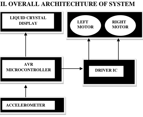
II. OVERALL ARCHITECHTURE OF SYSTEM
Figure 1: Block Diagram of Wheelchair System
Fig. 1 shows the functional block of the systems which is composed of 3-axis accelerometer sensor, the AVR ATmega16 microcontroller module and the DC servo motors module.
III. ACCELEROMETER
Accelerometer sensors have been used to measure acceleration in a variety of applications, including
automobile airbag crash sensors and seismic activity monitors. Single- and multi-axis models are available to detect magnitude and direction of the acceleration as a vector quantity, and can be used to sense orientation, acceleration, vibration shock, and falling.
Basic Theory of Operation
Accelerometer sensors convert either linear or angular39 acceleration to an output signal. Accelerometer sensors use
Newton’s second law of motion, F =ma, by measuring the
force from acceleration on an object whose mass is known. There are many ways to measure the force exerted on the mass, called a proof mass, but the most common method used in accelerometer sensors is measuring the displacement of the mass when it is suspended by springs. The mass spring system is diagrammed in figure-2.
Damper, B(x) Proof Mass, M
Spring, K (x)
external
Fixed Reference
Figure 2: Diagram of differential capacitive layout Forces acting on the proof mass include the force from external acceleration, the force from damping
(proportional to velocity), and the restorative force of the spring (proportional to position).
𝐹⃗=M𝑎⃗RexternalR=M𝑑
2𝑥⃗/𝑑𝑡2+B
(𝑥⃗) 𝑑𝑥⃗/𝑑𝑡+K (𝑥⃗) 𝑥⃗
In accelerometer sensors operating far from the resonant frequency of the mass-spring system, the effect of damping can be largely ignored. Some high precision accelerometer sensors operate near the resonant frequency to mechanically amplify the displacement from acceleration. For example, the JPL seismic accelerometer [6] is designed to have the resonant frequency at 10 to 25 Hz, and the bandwidth (operating range) of the sensor is 0.05 to 50 Hz. Furthermore, in the JPL sensor the cavity around
LEFT MOTOR
DRIVER IC
AVR
MICROCONTROLLER LIQUID CRYSTAL
DISPLAY
ACCELEROMETER
ISSN 2348 – 7968
511
the proof mass is evacuated to reduce the dampingcoefficient as much as possible, increasing the mechanical amplification.
For sufficiently small displacements, the spring constant K(x) can be assumed to be constant. In equilibrium when the mass is not moving, the restorative force exerted by the spring is equal to the force from acceleration on the proof mass. The displacement of the spring, x, is a parameter that can be converted to an
electrical signal by a variety of methods. The two common methods are measuring a change in resistance of a piezoresistive material and measuring a change in capacitance between moving and fixed electrical elements. An alternative way of directly measuring the acceleration force exerted on the proof mass is measuring a change in the charge of a piezoelectric material.
Micro machined accelerometers are increasingly present in portable electronic devices and video game controllers, to detect the position of the device or provide for game input. It is a capable of measuring how fast the speed of object is changing. It generates analog voltage as the output which is used as an input to the control system. The
accelerometer used in this system is ADXL335 (±1.5g
axis). It is a three axis accelerometer [5], which senses the tilts in three directions. The supply voltage is 5V. The device is sensitive to tilt in the 0g position.
IV. AVR ATmega16 Microcontroller
The ATmega16 is a low-power CMOS 8-bit microcontroller based on the AVR enhanced RISC architecture. By executing powerful instructions in a single clock cycle, the ATmega16 achieves throughputs approaching 1 MIPS per MHz allowing the system designed to optimize power consumption versus processing speed. The AVR core combines a rich instruction set with 32 general purpose working registers. All the 32 registers are directly connected to the Arithmetic Logic Unit (ALU), allowing two independent registers to be accessed in one single instruction executed in one clock cycle. The resulting architecture is more code efficient while achieving throughputs up to ten times faster than conventional CISC microcontrollers. The ATmega16 has 16 Kbytes of In-System Programmable Flash Program memory with Read-While-Write capabilities, 512 bytes EEPROM, 1 Kbyte SRAM, 32 general purpose I/O lines, 32 general purpose working registers, On-chip Debugging support and programming, three flexible Timer/Counters with compare modes, Internal and External Interrupts, a serial programmable USART, a byte oriented Two-wire Serial Interface, an 8-channel, 10-bit ADC with optional differential input stage with programmable gain[7].
V.
Liquid Crystal Display Fundamentals
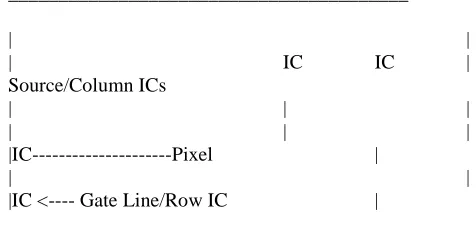
Liquid Crystal Displays (LCDs) are categorized as none missive display devices, in that respect, they do not produce any form of light like a Cathode Ray Tube (CRT). LCDs either pass or block light that is reflected from an external light source or provided by a back/side lighting system. There are two modes of operation for LCDs during the absence of an electric field (applied Power); a mode describes the transmittance state of the liquid crystal elements. Normal White mode: the display is white or clear and allows light to pass through and Normal Black Mode: the display is dark and all light is diffused. Virtually all displays in production for PC/Workstation use are normal white mode to optimize contrast and speed. In this system LCD is used for display direction of motion of wheelchair. A simplified description of how a dot matrix LCD display works is as follows: A twisted nematic (TN) LC display consists of two polarizer, two pieces of glass, some form of switching element or electrode to define pixels, and driver Integrated Circuits (ICs) to address the rows and columns of pixels. To define a pixel (or sub pixel element for a color display), a rectangle is constructed out of Indium Tin Oxide -- a semi-transparent metal oxide (ITO) and charge is applied to this area in order to change the orientation of the LC material ( change from a white pixel to a dark pixel). The method utilized to form a pixel in passive and active matrix displays differs and will be described in later sections. Figure 3 illustrates a cross sectional view of a simple TN LC display. Figure 4 depicts a dot matrix display as viewed without its metal module/case exposing the IC drivers.
Viewer
///////////////////////////////////// Polarizer
_____________________________________ Glass ~~~~~~~~~~~~~~~~~~~~~~~~~~~~~~~~~~~~~ Liquid Crystal
_____________________________________ Glass \\\\\\\\\\\\\\\\\\\\\\\\\\\\\\\\\\\\\ Polarizer
Backlight
Figure 3: Cross Section of a Simple LC Display ________________________________________
| |
| IC IC |
Source/Column ICs
| | |
| | |
|IC---Pixel |
| |
|IC <---- Gate Line/Row IC |
Figure 4: LCD panel and IC driver locations
ISSN 2348 – 7968
512
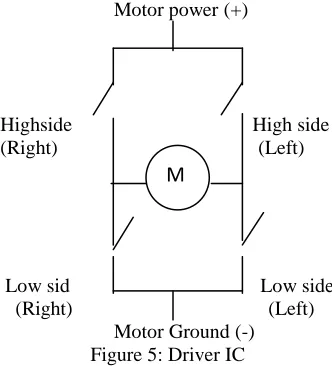
In this system two motors have been used. For the drivingof motors L293D is used as a driver [8]. It is a dual H-Bridge driver IC, so only one IC can drive two DC motors. Motors can be rotate in both clockwise and anti-clockwise direction. Motors are connecting with input/outputs of IC. L293D has output current of 600mA and peak output current of 1.2A per channel. Moreover for protection of circuit from back EMF output diodes are included. Due to wide range of output supply from 4.5V to 36V L293D is a best choice for DC motor driver.
Motor power (+)
Highside High side (Right) (Left)
Low sid Low side (Right) (Left) Motor Ground (-)
Figure 5: Driver IC
Driver IC has four switching elements within the bridge. These four elements are often called, high side left, high side right, low side right, and low side left (when traversing in clockwise order).
The switches are turned on in pairs, either high left and lower right, or lower left and high right, but never both switches on the same "side" of the bridge.
Table 2: Truth Table of L293D (One Channel) INPUT ENABLE(*) OUTPUT
H L H L
H H L L
H L Z Z
Z=High Output Impedance (*) Relative to consider
channel
VII. WORKING
The accelerometer is attached to a glove which is wear by the patient. On the movement of hand a tilt has been produced by the accelerometer. The tilt corresponds to the analog voltage. This analog voltage will be converted into
digital using AVR ATmega16 microcontroller. Based on accelerometer value the controller will generate control signals, which will drive the motors fitted to wheelchair. Thus the wheelchair can be driven in any of the four directions according to tilt of accelerometer. The direction of motion will be displayed on the intelligent LCD.
VIII. ANALYSIS
Performance of the system can be seen on the movement
of MEMS 3-axis accelerometer.The goal of this project is
the use of a three-dimensional accelerometer sensor system for measuring hand motion and provides movement to the wheelchair according to the tilt sense by the 3-axis accelerometer. The system includes the physical sensor, microcontroller that converts the analog voltage signal into digital signal, rotate the motor and display the direction of motion of wheelchair on LCD. Based on the goal of measuring involuntary hand motion, target parameters for the accelerometer system can be specified and are listed in Table 3. To measure complex hand motion occurring in three dimensions, the sensor needs to measure acceleration along three mutually perpendicular axes to reconstruct the total acceleration of the system. The bandwidth of the sensor needs to be from a fairly low frequency of about 0.1 Hz to the highest frequency possible for hand motion, about 25 Hz. The highest acceleration amplitude for hand
motion is about ±5 g, so this amplitude specifies the
acceleration range required. Higher acceleration amplitudes are possible with shock, but measuring this type of acceleration isn’t the goal of the project. However, the physical sensor should be able to withstand higher accelerations without being permanently damaged a maximum of ±50 g’s is reasonable. A resolution of 1 mg is appropriate for resolving very small involuntary accelerations in a normal human hand.
Table 3: Target Accelerometer System Parameters Parameter Target
Value
Number of Axes 3
Frequency Range
0.1 to 25 Hz Maximum
Acceleration Amplitude
+/- 5 g
Maximum Acceleration w/o
Damage
+/- 20 g
Acceleration Resolution
0.001 g
ISSN 2348 – 7968
513
frequency of finger tremor decreases 0.85 Hz for everygram of additional mass, and the peak frequency of hand tremor decreases by 0.018 Hz for every gram of additional mass. The amplitude of acceleration is also affected, but no solid data is presented. The physical target parameters are listed in Table 4
Table 4: Target Physical Accelerometer Sensor Parameters
One accelerometer sensor can sense the three different tilts. Based on the ground position each tilt will generate an output as a voltage. The sensor used in this automatic system generates an output voltage which varies between 2.5V to 3.5V is given to microcontroller as an analog input. Then it converted into digital signal using ADC of controller.
IX. RESULT
When a person wears a glove fixed with accelerometer and tilts his hand the wheelchair moves in corresponding direction based on the hand movement and LCD shows the direction of motion.
X. CONCLUSION
As the accelerometer sensor glove based robot system has been presented which will be very helpful for physically challenged persons who can move their all parts of body accept legs and for the persons who suffer with involuntary
disease. The 3-axis accelerometer sensor is calibrated such that it produces particular analog voltage for a corresponding tilt. AVR is programmed for analog to digital conversion as well sending data to LCD using AVR C compiler (AVR studio.4).
REFERENCES
1. International Tremor Foundation website
2. Stiles RN, Randall JE; Mechanical factors in
human tremor frequency; J Appl Physiol 1967-23(3):324-30.
3. Boose A
4. Website specifically concerning pediatric tremors
5. Lemkin MA, Boser BE, Auslander D, Smith JH; A
3-axis force balanced accelerometer using a single proof-mass; IEEE Transducers ’97, June 1997 Chicago.
6. Martin R., Pike W., Silicon micromachined
accelerometer/seismometer, NASA TechBriefs, Nov 98
7. Data sheet of AVR ATmega16 microcontroller.
8. Datasheet of L293D.
9. Data sheet of ADXL335
Parameter Target Value
Mass 5 grams