Wind Energy Stabilization Using SVPWM Based Modulated Power Filter Compensator
Page 433
Wind Energy Stabilization Using SVPWM Based Modulated
Power Filter Compensator
Fatehbir Singh
1, Shakti Singh
2Abstract:
During the last two decades, renewable wind energy has become increasingly popular as a consequence of strong ecological concerns and appealing advantages with regard to economical energy solutions in remote communities. However, the integration of dispersed renewable wind energy will pose a great challenge to the power quality in the distribution networks A Modulated power filter compensator is one of the FACTS devices used to improve the voltage profile of wind energy conversion system against changing wind condition and varying load condition. In this paper a SVPWM MPFC controller is designed .This SVPWM MPFC Controller is used to stabilize the varying wind energy output. The proposed controller is tested on system using Matlab Simulink Environment. The results are compared with conventional PWM based MPFC controller and found that results obtained with SVPWM controller are better than that of the results with PWM based controller.Index Terms: - FACTS, SVPWM based controller, MPFC, PWM
Wind energy
I. INTRODUCTION
The demand for the renewable energy sources increases as industrial sector become more aware about fossil fuel shortages and their environmental impacts [1]. Wind energy has become one of the most important alternative renewable energy resources because of its plentiful nature and the strong thrust for its commercialization. Most large size wind turbines in the world (50-2000kw) employ three phase asynchronous (squirrel cage) induction generator [2]. Induction generator has been most commonly used in wind energy conversion system. Due to its constant speed operation and variable wind speed, the power fluctuations are main problem in standalone system or in hybrid system [3]. Voltage stability is main problem for standalone wind energy conversion scheme using induction generator, under severe wind gusting and dynamic load variation. So a novel stabilization scheme is used that ensures voltage stability is required for a stand-alone wind energy conversion scheme[4]. MPFC controller is utilized to provide voltage stabilization against gusting wind condition and varying load condition.
FB. Singh is perusing M.E from EIED, Thapar University Patiala, Punjab, India (e-mail: [email protected]).
S. Singh is working as Assistant Professor in EIED , Thapar University Patiala, Punjab, India (e-mail: [email protected]).
In order to improve the power quality problem in the distribution systems that are merged with renewable energy sources (RES),a switched modulated power filter compensator (MPFC) which is driven by a tri-loop error controller is employed.
Fig.1 MPFC Controller [5].
Wind Energy Stabilization Using SVPWM Based Modulated Power Filter Compensator
Page 434
keep a near maximum energy utilization under load and wind varying conditions [1].
II. WIND INDUCTION GENERATOR TEST SYSTEM
Fig.2. shows sample study system of WCES. Sample study system has wind turbine with a gearbox which is coupled to induction generator which produces electrical energy output, this electrical energy output is being stepped up using step up transformer and is transmitted to distribution system via transmission line ,on this end level of voltage is stepped down using step down transformer which is then fed to the consumers. Due to the presence of non linear load and varying wind conditions, voltage profile became worsen so modulated power filter compensator is being employed to stabilize the wind energy output.
Fig. 2 Sample Wind Induction Generator Test System [1].
The sample study system is tested for serve electric load excursion. From Starting to 0.2 sec both linear and non linear load are connected. From 0.2 sec to 0.4 sec, only linear load is connected. The dynamic performance of system is compared with controller using PWM technique and SVPWM based technique.
III. SVPWM TECHNIQUEBASEDMPFCCONTROLLER
Space vector modulation technique was first introduced by German researchers in 1980s. This technique has showed several benefits over the traditional PWM technique and has been prove to be inherently generating superior PWM waveforms. The concept of space vector is obtained from the rotating field of AC machine which is used for modulation of the output voltage of the inverter. In this modulation technique the three phase quantities can be changed to their equivalent two phase quantity either in synchronously rotating frame (or) stationary frame. From these two-phase components, the reference vector is be found and it can be used for modulating the output of inveter [7] The basic difference between SVM technique and PWM technique is that it treats the inverter as a whole unit, which is not the case when compared to PWM
technique. This technique
is
based on the decaying of areference vector of voltage into voltage vector dependable on a six pulse inverter [8].In SVPWM Technique, Let the three phase sinusoidal voltage component be,
Va =Vm sin ωt (1)
Vb =Vm sin (ωt-2π/3) (2) Vc =Vm sin(ωt-4π/3) (3)
When this voltage is applied to the AC machine it produces a flux which is rotating in the air gap of the machine. The rotating flux component could be represented as single rotating voltage vector. The magnitude and angle of the rotating vector could be found by mean of Clark’s Transformation. The representation of rotating vector in complex plane is shown in Fig. 3.
Fig.3 Space vector Representation of Inverter output Voltage [7].
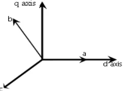
Space vector PWM implementation require, voltage equations in the abc reference frame to be transformed into the stationary dq reference frame that consists of the horizontal (d) and vertical (q) axes as shown in Fig.4
Fig.4 The relationship of abc reference frame and stationary dq reference frame
Wind Energy Stabilization Using SVPWM Based Modulated Power Filter Compensator
Page 435
f k f (4) Where
K 2/3 10 √3/21/2 √3/21/2 1/2 1/2 1/2 f f f f
f f f f
f =denotes either voltage or current variable This transformation is identical to an orthogonal projection of
onto the two-dimensional vertical to the vector
1 1 1 (the equivalent d-q plane) in a three-dimensional system. As a result of which, two zero vectors and six non zero vectors are possible. Six non-zero vectors V V! shape the axes of a hexagonal as depicted in Fig 2.1 and supplies power to the load. The two adjacent two non-zero vectors have an angle of 60 degrees. Meanwhile, two zero vectors (V,V# ) are at the origin and apply zero voltage to the load [8]. For 180° mode of operation of inverter, six switching states and additionally two more states are there, all three switches of either upper arms or lower arms make ON. For these eight states to be coded in binary (one-zero representation), three bits are required (2$ 8) and also, as always upper and lower switches are turned off in complementary fashion, it is sufficing to represent the status of either upper or lower arm switches. Status of the upper bridge switches will be given and the lower switches will it’s opposite. Let "1" denote the switch is ON and "0" denote the switch in OFF.
Let us assign each switching states as vector in complex plane:
V = 000 (Q , Q$ and Q& OFF and Q', Q( and Q ON)
V = 100 (Q ON Q$ and Q& OFF)
V' = 110 (Q and Q$ ON; Q& OFF) V$= 010 (Q$ ON; Q and Q& OFF)
V( = 011 (Q$ and Q& ON; Q OFF)
V& = 001 (Q& ON; Q and Q$ OFF) V= 101 (Q and Q& ON; Q$ OFF)
V# = 111 (Q , Q$ and Q& ON and Q', Q(and Q OFF) [9]. The reference V)*+ is rotating space-vector type of three-phase voltage. The estimation of V)*+ in the α-β plane at any period will lie in the area of any one of the sector [7]. Two vectors edge each sector and each of them link to a fixed period of time. The time integral value of V)*+ , can be approximated by the sum of the products of the two of vectors and their time widths.For example, in figure 1, reference, V)*+ lie in a sector which is edged by vector V and V' . Starting from time , , V)*+ moves to t1 and an approximation for the time integral can then written as
- V0/ )*+ T V 1 T'V' (5)
Where T and T' represent the time widths for vectors V and
V' respectively and the integration time interval t to t are the sampling period (much less than period corresponding to one sector). By regulating T and T', right hand side of this expression can be made close to left-hand side value .Thus, by keeping the inverter-switching mode as V for a time period
T and V' for a time period T', the pulse pattern during the period t to t is found .The same approximation (by V and
V') is repeated for all samplings of this sector [9].Table 1 shows Switching Vector and Corresponding Voltage.
Table 1 Switching Vector and Corresponding Voltage [8].
Time duration for different sector can be determined as follows as shown in Fig.5
Fig.5 Reference vector as combination of neighbouring vector at sector 1
- 378 456 - 37/ 1 -77//9:;3'1 -77/;<7;3 (6)
=>3456 = 3 1 ='3' (7)
=> ?3456@ Acos Esin EH = I2J K33 LMA10H 1 ='I2 3J K3LMN cosO$ sinO$P (8)
(Where 0≤α≤ QJ3)
Therefore Voltage
Vector
Switching
Vectors
Line to Neutral
Voltage
Line to Line
Voltage
A B C VR VR VR V V V
V 0 0 0 0 0 0 0 0 0
V 1 0 0 2/3 1/3 1/3 1 0 -1
V' 1 1 0 1/3 1/3 2/3 0 1 -1 V$ 0 1 0 1/3 2/3 1/3 -1 1 0 V( 0 1 1 2/3 1/3 1/3 -1 0 1 V& 0 0 1 1/3 1/3 2/3 0 -1 1
V 1 0 1 1/3 -2/3 1/3 1 -1 0
Wind Energy Stabilization Using SVPWM Based Modulated Power Filter Compensator
Page 436
= => sinIQ 3J EK / sin SO
$T (9)
=' => sin E! / sin SO$T (10)
= => = 1 =' ! (11)
Where
=> 1/UV and a= WXYZ
'/$W[\
Where=, = , =' represent the time widths for vectors3,3 , 3'. = is the period in a sampling period for zero vectors. As each switching period (half of sampling period) Tz starts and ends with zero vectors i.e. there will be two zero vectors per => or four null vectors per Ts, duration of each null vector is =/4 [7].
IV. SIMULATION MODEL
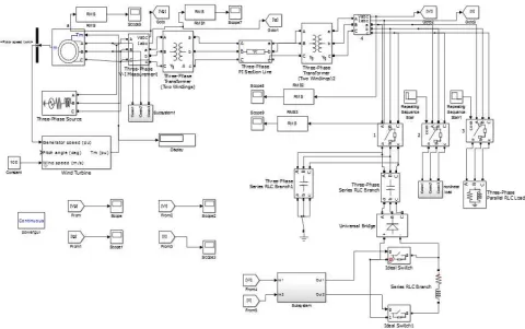
Simulink Model of wind energy conversion system as shown in appendix Fig. 14. The induction machine equipped with wind turbine act as induction generator. The output of induction generator has fluctuating nature due to variable wind speed and series of load excursion that are there on the system. Different types of loads that are present on the system are linear load of 100 MVA and non linear load of 100 MVA. SVPWM based MPFC controller is used for voltage improvement and the results obtained through simulation is compared with PWM MPFC controller. Given simulation model run under continuous mode.
V. SIMULATIONRESULTS
Simulation results are obtained by employing two controllers on the given system as shown in Fig.14.Firstly a SVPWM based MPFC controller is employed on the system and then afterwards PWM based controller is applied and it s found that results obtained with Chaos based SVPW controller is better than that of results obtained with PWM based controller.
Case a). SVPWM based MPFC controller:
With Matlab/Simulink environment variation of load end voltage v/s time shown in Fig 6, load end current v/s time shown in Fig.7, sending end voltage v/s time shown in Fig.8 and sending end current v/s time shown in Fig.9 are obtained.
Fig.6 variation of load voltage v/s time of SVPWM based MPFC controller
Fig.7 variation of load current v/s time of SVPWM based MPFC controller
Wind Energy Stabilization Using SVPWM Based Modulated Power Filter Compensator
Page 437
Fig.9 variation of sending end current v/s time of SVPWM based MPFC controller
Case b).PWM based MPFC controller:
With Matlab/Simulink environment variation of load end voltage v/s time shown in Fig 10, load end current v/s time shown in Fig.11, sending end voltage v/s time shown in Fig.12 and sending end current v/s time shown in Fig.13 are obtained.
Fig.10 variation of Load end current v/s time of PWM based MPFC controller
Fig.11 variation of load end current v/s time
of PWM based MPFC controller
Fig.12 variation of sending end voltage v/s time of PWM based MPFC controller
Fig.13 variation of sending end current v/s time of PWM based MPFC controller
Wind Energy Stabilization Using SVPWM Based Modulated Power Filter Compensator
Page 438
Table 2. Results obtained with different controllers used
VI. CONCLUSION
In This Paper, based SVPWM based MPFC controller is successfully designed for providing dynamic voltage stabilization in wind energy conversion system. This control strategy is compared with conventional PWM based MPFC controller for the system as shown in Fig 14. Simulation results indicate that SVPWM based MPFC controller provides better voltage stabilization as compared PWM based MPFC controller.
VII. APPENDIX
A. Data
Data for various components used in matlab simulink model of Fig are as follows:
1. System per unit base: S^ 3.6MVA
3c 11KV/25KV/600V (Generation/Transmission/Load end) 2. Induction Generator Parameters: Sd 3.6MVA
3e 11f3
a. Stator: R 0.016 pu LI 0.06 pu b. Rotor: Rl) 0.015 pu LIl) 0.06 pu 3. Transformer Parameters:
a) 11KV/25KV (L-L) Transformer (T1)
Generation side: 11KV/3.6MVA,R=.002 pu L=.08 pu Load side: 25KV/3.6MVA, R=.002 pu L=.08 pu
b) 25KV/600V(L-L) Transformer(T2)
Generation side: 25KV/3.6MVA R=.002 pu L=.08 pu Load side: 600V/3.6MVA R=.002 pu L=.08 pu 4. Transmission Line/Feeder: Length: 10km
Positive Sequence parameters: n 0.01273ohms/km
L .93373e 3 H/km, C 12.74e-9 F/km 5. The SVPWM based switching power filter: Filter
capacitor bank:C+=1.7 mF/phase Filter inductance: L+=30mH Filter resistance: R+ .25ohms
6. Tri loop error driven PID Controller:γw γx
1, γy .5,PID Controller Gains :Kz 0.5, Kx
.05, K .01
7. Load sequence excursions:
From 0s to 0.2s: linear load 200KVA (50%) Non linear load 200KVA (50%) From 0.2s to 0.5s: linear load 200 KVA (50%) only
S.No. Controller With
different PWM technique used
Voltage profile on load end side
Harmonics content in
output voltage and
current
1 PWM based
Controller
Distorted Large
2. SVPWM based
Controller
Wind Energy Stabilization Using SVPWM Based Modulated Power Filter Compensator
B. Simulation diagram
Fig. 14Simulation Diagram for Wind ener
Wind Energy Stabilization Using SVPWM Based Modulated Power Filter Compensator
Simulation Diagram for Wind energy conversion system using SVPWM based MPFC controllerWind Energy Stabilization Using SVPWM Based Modulated Power Filter Compensator
Page 439
Wind Energy Stabilization Using SVPWM Based Modulated Power Filter Compensator
Page 440
C. Subsystem for SVPWM based MPFC controllerFig. 15 Subsystem for SVPWM based MPFC controller
VIII. REFERENCES
[1] A. M. Sharaf, “A Low-Cost Voltage Stabilization and Power Quality Enhancement Scheme for a Small Renewable Wind Energy Scheme,” IEEE International Symposium on Industrial Electronics, Vol. 3, pp. 1949-1953, 2006.
[2] A. E. Fitzgerald, “Electric Machinery,” McGraw-Hill Book Company, New York, 2002.
[3] W. Huang, “Direct voltage control for standalone wind energy conversion system using induction generator and energy storage,” IEEE Electric Power conference, pp 1-8, 2008.
[4] A. M. Sharaf, “Wind energy system voltage and energy enhancement using low cost dynamic capacitor compensation scheme,” IEEE international conference on Electric, Electronics and Computer engineering, pp 804-807, 2004.
[5] T. Aboul, “A novel modulated power filter compensator scheme for standalone wind energy utilization systems,” Canadian conference on Electrical and Computer Engineering, pp 390-393,2009
[6] A.M. Sharaf, “An novel modulated power filter compensator for distribution network with distributed wind energy,” International journal of emerging electric power system, Vol 8, pp 549-555,2007. [7] D. Rathnakumar, “A new Software Implementation of space vector
PWM,”
IEEE Proceedings SoutheastCon, pp. 131-136, April 2005.
[8] Zhenya Yu, “A Review of Three PWM Techniques,” Proceedings of American control conference, New Mexico, Vol 1, pp. 257-261, june1997.
[9]
[10]
B.K. Bose; "Power electronics and ac drives,” Prentice Hall Inc., Englewood Cliffs, New Jersey, 1986.
John K. Kaldellis, “Comprehensive Renewable Energy,” Vol. 2, Elsevier Ltd., 2012.