Sequential Algorithm for Convert Fractional
Radix 10 to Radix 2
Gelacio Castillo C1, M. Patricia Jiménez V2., M. del Rosario Rocha B3
Titular Professor of University, DEPTO. ISC,Escuela Superior de Cómputo del Instituto Politécnico Nacional1
Titular Professor of University, DEPTO. FB, Escuela Superior de Cómputo del Instituto Politécnico Nacional2
Titular Professor of University, DEPTO. CIC Escuela Superior de Cómputo del Instituto Politécnico Nacional3
ABSTRACT:A sequential algorithm to convert from fractional decimal number to fractional radix 2 (binary) is proposed here. This algorithm describes only the procedure to carry out conversion of Fractional part. Then, a condition for stop converting and one for approximation are not discussed here, but in the Standard IEEE 754 2008. The procedure of conversion many times is taken for granted, however, this algorithm is so very useful for design and implementation of units of floating point, in ASIC design for sensors applications with floating point unit. Moreover, that are not tacitly and clearly settled down, in the state of the art, how do you can introduce from keyboard, digitize, and normalize.Therefore, the main contribution in this article is release it,so that itcan be used in design of customized cores of Floating Point, from the level of registers and logic gate.
KEYWORDS:Binary, conversion, decimal, Fractional number, Sequential algorithm.
I.INTRODUCTION
II. IEEE FORMAT
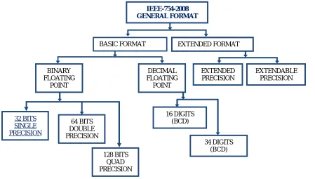
We can make a tree like a map for a graphical view of IEEE 754 2008. That is shown in the Fig. 1. In order to put in context, the contribution of this article, analyse us in which branch we are located (underlined words in the map).
Fig 1.- Graphical representation of IEEE 754 2008 [1]
In our approach we will focused in the branch “32 BITS SINGLE PRESISION”, to the left in the map Fig. 1. Assume that user can write a real number on anyof the following equivalent ways.
Table 1
Different ways that user can type a real number
1 = 735.864 3 = +7.35864∗10 5 = +735864.0∗10
2 = 7.35864∗10 4 = +0.735864∗10 6 = +7358.64∗10
Expression 2 in the Table 1 is as humans write real number in standard way called “Scientific Notation”. The expression 1 is one case in which a human can type a real number from keyboard [11, 12], as Fig. 2. It has clearly an “Integer part” and one “Fractional part”.
32 BITS SINGLE PRECISION
64 BITS DOUBLE PRECISION
128 BITS QUAD PRECISION
16 DIGITS (BCD)
34 DIGITS (BCD) BINARY
FLOATING POINT
DECIMAL FLOATING POINT
EXTENDED PRECISION
EXTENDABLE PRECISION BASIC FORMAT EXTENDED FORMAT
Fig. 2.
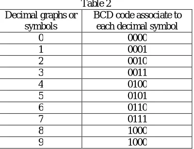
Table 2 shows BCD code. Assuminga number is typed like expression 1 in the Table 1, that is, = 735.864. It is saved in two registers as in the Table 3, a register called “Integer part” and other called “Fractional part”.
Table 2 Decimal graphs or
symbols
BCD code associate to each decimal symbol
0 0000
1 0001
2 0010
3 0011
4 0100
5 0101
6 0110
7 0111
8 1000
9 1000
Immediately a number is typed, it is caught in BCD, as in the Table 3. Each symbol of decimal system has associated a binary code and it is the BCD code.
Table 3
Equivalent form a decimal number
Integer part Fractional part
Decimal symbols 735 864
BCD code symbols 0111 0011 0101 1000 0110 0100
This article is focused only the conversion of Fractional decimal part to Fractional binary. Other works have focused in the conversion of “Integer part” [8, 9 10]. In this case Fractional Decimal 1000 0110 0100, Table 3, is equivalent to symbol 864. In any other case of Table 1, we would have a Fractional part, except in expression 5 (Table 1). Option followed here is consider a general way, which is reserve a register for sign, one for integer part, one for Fractional Part and the last one for exponent. After each of this field have been converted to binary, integer part and Fractional part register would be concatenated. Then shift this new register[5, 6] which will be called mantissa in order to get IEEE format as is shown in the Table 4.
1 2 3
4 5 6
7 8 9
0 * + - ÷ A
Table 4
IEEE format 32 bit. Single precision sign exponent mantissa One bit 8 bits 24 bits
III. FLOWCHART ALGORITHM
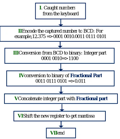
Fig.3 shows the flowchart for process of conversion of Fractional part of a real number typed by user.The steps, from introduction of a number from keyboard until that conversion has finished and gotten register mantissa.When a button, or a field of the sensitive area, as in a touch pad [13, 14, 15, 16, 17, 18] has been press on with, a process of hardware is started in for encoded each button, area, or zone of map pushed.
Fig.3Flowchart for Processing of Numbers
IV. CATCHING NUMBER FROM THE KEYBOARD
As stated before, when a button, area, or zone, as in a touch pad has been press on with, a process of hardware is started in for encoded each zone of map pressed on. Each one push inputs to an encoder and then each symbol is encoded to binary BCD code as is shown in the Tables3 and 5. User introduce Floating Point number, in general in the following format:
VConcatenate integer part with Fractional part
VIIend
VIShift the new register to get mantissa IIIConversion from BCD to binary: Integer part
0001 0010=> 1100
IVconversion to binary of Fractional Part 0011 0111 0101 => 0.011
IIEncode the captured number to BCD: For example,12.375 => 0001 0010.0011 0111 0101
∗ ∗ ∗10 (1) In the Table 5we will pay attention just in Fractional part.
Table 5
Decimal graph (symbol) BCD code of each symbol captured
Sign*Integer∙Fract*10exp Source Register (Store number floating point encoded on BCD)
D U P NB1 NB2 NBm
3.425 0000 0011 point 0100 0010 0101 8.771 0000 1000 point 0111 0111 0001 3.946 0000 0011 point 1001 0100 0110 5.732 0000 0101 point 0111 0011 0010
We will assume that SR is the Source Register, where at the beginning Fractional field has been caught as in the Table 5, organized in nibbles, NB1, NB2, NBm. And we will focus only in the Fractional Part.
= 1 2 3 ⋯ (2)
In the process of conversion, we will use a target registry (TR) to pick up result.
= (3)
V. POLINOMIAL REPRESENTATION OF A REAL NUMBER
2 + 2 + 2 +⋯+ 2 + 2 + 2 +⋯+ 2 (4)
Coefficients a belong to symbols of radix 2, that is, 0’s and 1’s. Exponents numbers n and k be-long to radix 10 integers [2, 5]. The first weights of fractional part are shows on the Table 6 as follow.
Table 6
Fractional position
weight
2 0.5
2 0.25
2 0.125
2 0.0625
2 0.03125
2 0.015625
2 0.0078125
2 0.00390625
VI. ALGORITHM FOR CONVERT FRACTIONAL DECIMAL TO FRACTIONAL BINARY
The algorithm is very simply. Consist in multiply by 2. This operation is does by shifting SR to the left, move to the left one bit at a time, by each iteration. The bit which go out by the left is saved in the TR. It is outlined as follow: In the Table 7 the numbers Ds are digit (radix 10) encoded in BCD, four bit each one. Numbers Br are binary units (radix 2), bits ‘0’ or ‘1’. We will assume that subscript S is the amount of captured digit in the fractional part. Subscript R is the resolution defined on IEEE 754 2008 [1].
Table 7
Source Register (SR) Target Register (TR)
… …
FIRST ITERATION
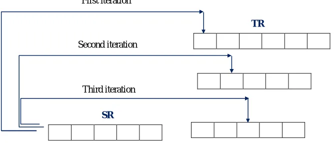
STEP 1.- Compare each digit encoded in BCD (DS) with the number four whose representation on radix 2 is 0100. If D is larger than 0100 then add 0011, else nothing.
STEP 2.- Shift Source Register (SR) to the left. There is a binary unit (bit), or binary number, what go out by the left. It will be the first binary number saved in the Target Register (TR).
STEP 3.- Replace the binary number (bit) in the first position (B1) at the left in the Target Register (TR) by the bit which came out from the left in the SR. In other word, in the first iteration, in the position B1 put the binary number which came out at the left in the SR.
SECOND ITERATION
Repeat steps as in the first iteration. Now de second bit which come out from the left in the SR it will put in the second position (B2) from the left to the right in the TR as it is indicated in the Figure 4.
THIRD ITERATION
Repeat steps as in the first iteration. Now de third bit which come out from the left in the SR it will put in the third position (B3) from the left to the right in the TR, as it is shown in the Figure 4.
The process finish when or where the criterion of resolution R is defined [IEEE].
Fig 4. Graphical description of steps 2 to 3
∙∙∙
∙∙∙
∙∙∙ ∙∙∙
SR Third iteration Second iteration
First iteration
As example take the real number (Table 1) = 735.864, and by applying the previous algorithm we get as result
= 1011011111.11011101000111 … (5)
We stop the process when reach the IEEE single precision format, which is of 32 bits (see Fig. 1), with mantissa of 24 bit. However, in the Fractional part, the process yet not finish. Then, it must be applied the "rounding-direction attributes to nearest" [1], or, truncation by rounding [2, 5]. Our goal finish in expression (5). But, furthermore, we can say that the mantissa is:
= 01101111111011101000111 (6)
Where the first ‘1’ to the left is implicit. The point or dot has be shifted to the left.
VII.CONCLUSION
There is case where conversion not finish, as in the example of expression (5). However, it must be stop as is states by IEEE selected format., single precision 32 bits, double precision 64 bits or other. Then truncation by rounding.
This proposal imply divide in fields, a real number, to facilitate the processes implicitly contents of floating-point, and thus later, its standard implementation.
We recommend modular develop for its implementation. Registers of shifting, substitutions, unsigned adds in four bit, comparations, counters, are elementary operations, which must be arranged inside of FPGA.
The algorithm is feasible. Many books have it inside of his pages. But no one have given description how it can catch from keyboard with programmable Logic Device (PLD), as a FPGA, and how process it. Suppose the following Floating-Pointnumber:
=−826∗09123∗10 (7)
Users typically introduce a number from the keyboard by through expression (7). Here the number must be caught by registers. Then to apply the process for conversion and then normalization in IEEE format.In the practice each field must be caught by registers called sign, integer part, fractional part, and exponent. The evaluation is not part of this article.
REFERENCES
[1] IEEE Computer Society (2008). IEEE Floating-Point Arithmetic. IEEE Std. 754. Revision 29 August 2008.
[2] Patterson D. A., Hennessy J. L.(2012). Computer Organization and Design. The hardware/Software Interface. University of California, Berkeley. Stanford University. 2012 Elsevier.
[3] Antelo E., Bóo M., Bruguera D. J., Zapata L. E. (1998). A novel Design of a Two Operand Normalization Circuit. IEEE Transaction on Very Large Scale Integration (VLSI) systems. Vol. 6, No. 1, March 1998. Page 173-176.
[4] Hossam H. A. F with permission of Flynn J. Michael (1982). Computer Arithmetic. Page 33.
[5] Joseph Cavanagh (2013). X86 Assembly Languaje and C Fundamentals. Santa Clara University, SantaClara, CRC Press Taylor and Francis Group. Boca Raton London New York. California.Page 446.International Standard Book Number-13: 978-1-4665-6825-9 (eBook - PDF). [6] Cavanagh J (2008). Digital Design and Verilog HDL Fundamentals. Santa Clara University. California, USA. CRC Press. Taylor and Francis
Group. Page 24.
[7] Sivarama P. Dandamudi (2005). Guide to RISC Processors. For Programmers and Engineers. Sringer. School of Computer Science. Carleton University. Ottawa, ON K1S 5B6. Canada. [email protected]. 2005 Springer Science+Business Media, Inc.
[8] P. Alfke and B. New (1997). Serial Code conversion between BCD and binary. Applica-tion Note XAPP 029. Xilinx.
[9] Castillo C. G., Lomelí G. A. A., Aviña G. J., Mata B. L. E. (2017). Convertidor mixto de decimal entero (BCD) a binario entero. XVIII Simposium Internacional. Escuela Superior deCómputo, Instituto Politécnico Nacional. 2017.
[10] Priya H. A. (2015). A High Performance Binary to BCD converter. International Journal ofAdvanced Research in Electrical, Electronics and Instrumentation Engineering. 2015, Vol. 4,Issue 8, August 2015.
[11] AN0040 Silicon Labs (2013). Hardware Design for Capacitive Touch. EFM32. www.silab.com.
[12] R01AN3825EU0101 Application Note(2017). Renesas. Capacitive Touch Hardware Design and Layout Guidelines for Synergy, RX200, and RX100. Renesas Synergy TM Platform. Jun 14, 2014.
[14] OxkarRönnqvisit. Touch sensitive user interface module for ARM Cortex-M3. Master of Science Thesis MMK 2011:24 MDA403. KTH Industrial Engineering and Management. Machine Design. SE-100 44 STOCKHOLM. 2011-03-23.
[15] Hotelling et al. Multipoint Touchscreen. United States. Patent Application Publication. Patent US 2006/0097991 A1. May 11, 2006.
[16] Kim H. K., Lee S., Yun K. S.(2011). Capacitive tactile sensor array for touch screen application. Sensor and Actuators A: Physical. 165 (2011) 2-7. Elsevier.
[17] Wigdor D. (2012). Invited Paper: The Bread-Depth Dichotomy: Opportunities and Crises in Expanding Sensing Capabilities. Pages 845-848. First Published: 16 August 2012. Wiley Online Library. Society for Information Display (SID). International Symposium. Digest of Technical Papers. Volume 42, Issue 1. June 2011.