Page | 627
Performance Improvement of Wireless communication System of
DSCDMA with Rake Receiver
1Mr. Khaire Ganesh B
.& 2Prof. R.B. Sonawane
Dept.ofElectronics AVCOE, Sangamner India, Affiliated to university of Pune.
[email protected] ; [email protected]
Abstract—
This paper develops a performance of DS-CDMA wireless communication system over a multipath fading channel is examined. The analysis is related to DS-CDMA with Rake Receiver. BER is a strategic parameter that is used in evaluating systems that transfer digital data from one place to another. Rake receiver having many fingers also called sub-receiver. In which received signal get multiplied with time delayedforms of locally generated code sequence.To takings advantage of the SNR and minimize the BER the CDMA Rake receiver is used. Using rake receiver we have better signal than without rake receiver. It is used in CDMA as effectual multipath signal reception, where several receptors are able to reconstruct the same signal with different time codes, amplitude & phase. A Fading Channel is well-known as communications channel. In this paper different fading systems also briefly explained. BER simulation is done using MATLAB as software tool.
IndexTerms—
BER (Bit Error Rate); DS-CDMA (DirectSequence-CDMA); Error Control Coding; Fading; Multipath Fading Channels; Rake Receiver
1. INTRODUCTION
Many modern communication systems, like wirelesscellular systems, operate in environments that areinterference and
bandwidth limited, where
propagationcharacteristics are more problematic
and multipath-inducedfading and shadowing are a common problem. Rake receiver consists of multiple fingers or correlators, in which the receive signal multiplied with time-delayedforms of a nearbyformed code series. To maximize the SNR and minimize the BER the CDMA Rake receiver is used. In a wireless mobile communication system, a signal can travel from transmitter (TX) to receiver (RX) over multiple paths; this phenomenon is referred to as multipath propagation. There are many systems that define the method of fading either small or large scale. Out of these replicas, Rayleigh fading, Rician fading and Nakagami fading replicas are most widely used. It is important to calculate the performance of wireless devices by considering the transmission characteristics, wireless channel parameters and device structure. The performance of data transmission is well calculated by observing BER [3] at the receiver. In wireless channels, several models have been proposed and investigated to calculate SNR. Nowadays We are using three modeling techniques which depends on characteristics of signal.The techniques are Additive White Gaussian Noise (AWGN), Rayleigh and Rician models. The signal is found and recover by employing several models of the received signal. So, structure with multilink we have considered. The physical layer is used particular modulation technique.
Page | 628
Error Control coding is a technique where redundancy is added to the original bit sequence to increase the reliability of the communication [4].
Rake Receiver isused in CDMA cellular systems which can combine multipath mechanism, which are time delayed forms of the original signal transmission. This combining is done to improve SNR at receiver [1], [2].
2.WIRELESSCHANNELMODELING Wireless communication is one of the majoritylively areas of today‟s life. Wirelesschannels have to be simulate accurately and itis very important for the implementing the system. Performance of system totally depends on accuracy of design and simulation results. Multipath phenomenon is important also to considerthat loss of signals. Fading is another major and challenging issue that leads us to the design fading models accurately depends upon different environments and conditions. Even though no model can „accurately‟ describe an environment, they struggle to obtain as much exactness as possible. The better fading model is that it can compensated with other signal. At receiver end we get totally noise free signal with high voice quality.
FADING AND MULTIPATH
Carrier-modulatedcommunication signal experiencesdistortion over certain propagation media. Fading is occur due multipath propagation referred as multipath induced fading. Multipath means that more than one signal receiving
at the Receiving antenna. Causes of multipath include reflections, refractions, scattering & Doppler shift. Fading is mainly due to distortions at the receiving end. The phenomenon of reflection, diffraction and scattering all give increase to added radio propagation paths ahead of the direct optical Line Of Sight (LOS) path between the radio transmitter and receiver [14].
3. RAKE RECEIVER
The block diagram of DS-CDMA with Rake Receiver is as shown in figure 2. In multipath channel, delayed reflections interference with the direct signal in a DS-CDMA can be detected by rake receiver, a RAKE receiver uses several baseband correlates to individual multipath components. The correlators or fingers are combined to increase SNR (Signal To Noise Ratio). RAKE receiver, used particularly in CDMA systemthat combine multipath signals, which are time-delayed forms of the transmitted original signal.At transmitting end many signals are transmitted because of reflections it causes each signal having different amplitude, phase and delays. At the receiving end RAKE receiver is used to combine multipath signals & recovered them. This combination is done for toincrease the performance of the system i.e. to increase signal to noise ratio (SNR) at the receiver. RAKE receiver efforts to accumulate the time shifted forms of the unique signal throughprovided that a separate sub-receiver for each of the multipath signals those are coming from transmitting side. It uses a multiple path diversity principle. It is similar a rake that degenerates the energy from the multiple signals which are propagated.
Page | 629
i.e. main component of signal. The spread code have to be selected with a very small autocorrelation value because for any non-zero time counterbalance that avoids crosstalk between fingers or sub receivers. It does not determine a full periodic autocorrelation which shows that the crosstalk between signals in dissimilar fingers, but rather than this two partial correlations have to be considered with influences from two uninterrupted bits or symbols. It is necessary to find sequence that have at least satisfactory partial correlation values, but the cross talk due to non periodic correlations leftoversconsiderablyadditional difficult.The rake receiver is designed to optimally detect as DS-CDMA signal transmitted over dispersive multipath channel. Like a garden rake, the rake receiver collects the energy received from the different delayed propagation paths. According to theb principle of maximum ratio, the SNR at the output side or receiver end is the sum of SNR‟s in the distinct divisions, delivered that, We assume that only AWGN channel is present and codes with time offset are truly orthogonal.
Fig. 2. Simple Block Diagram of DS-CDMA with RAKE Receiver.
4 .FADING CHANNELS
A Fading Channel also named as communications channel which has to go through different fading phenomenon‟s, during communication communication channels has to go through many different distortions i.e. fading. In today‟s world surroundings, the many propagation effects combine together and multipath is created by these communication channels. All received signal is added at the receiver. Some signal have direct path so these
signal get subtracted. In wireless communication channel, transmitted signal can travel transmitter mobile station to receiver station over many paths.There are two types of fading slow fading / fast fading and frequency -selective
4.1TYPES OF SMALL SCALE FADING
Figure 3.Types of small scale fading 4.1.1Rayleigh fading model
The Rayleigh fading is primarilycaused by multipath reception [6]. Rayleigh fading is a statisticalmodel for the effect of a propagation environment on a radiosignal. It is a reasonable model for troposphere and ionospheres’ signal propagation as well as the effect of heavily built-up urbanenvironments on radio signals. Rayleigh fading [7] is mostapplicable when there is no line of sight between the transmitterand receiver.
4.1.2 Rician fading model
The Rician fading model [6] is similarto the Rayleigh fading model, except that in Rician fading, astrong dominant component is present. This dominantcomponent is a stationary (non fading) signal and is commonlyknown as the LOS (Line of Sight Component).
Page | 630
wheres(t) is transmitted signal and n(t) is background noise.
4. MULTIPATH FADING CHANNEL MODEL
A tapped-delay line model shown in figure 1 demonstrates both the properties of flat and frequency selective fading. Each multipath signal has a different time delay (τ), amplitude level (α) and phase shift (Ǿ), which will interfere with one another at the receiver, producing a totally distorted version of the original transmitted signal with the additive of noise [5].
Figure 4: Tapped delay line model of a multipath fading channel.
5.BINARY PHASE SHIFT KEYING MODULATION
The phase of a constant amplitude carrier signal is switched between two values according to the two possible signals m1 and m2 corresponding to binary 1 and 0, respectively. Normally, the two phases are separated by 180°. If the sinusoidal carrier has an amplitude Ac and
energy per bit Eb, then the transmitted BPSK signal for 0≤ t ≤Tb is either:
For binary 1input (Signal m1)
𝑆𝐵𝑃𝑆𝐾 𝑡 = 2𝐸𝑏
𝑇𝑏 cos(𝜋2fct + θc)(1)
For binary 0 input(Signal m1)
𝑆𝐵𝑃𝑆𝐾 𝑡 = − 2𝐸𝑏
𝑇𝑏 cos(𝜋2fct + θc) (2)
Where, 𝐸𝑏 =
1
2𝐴𝑐
2𝑇 𝑏
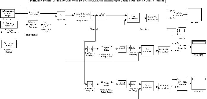
6. SIMULINK MODELS
Figure 5 shows a single-user system Simulink model in which the signal is transmitted over multiple paths. This is similar to a mobile channel environment where the signals are received over multiple paths, each of which has different amplitudes and delays. To take advantage of the multipath transmission, the receiver employs diversity reception which combines the independent paths coherently. The model uses random binary data which is BPSK modulated (real), spread by PN codes of and then transmitted over different channel. The receiver consists of a despreader followed by a BPSK demodulator.
Page | 631
As shown in figure 6 , Multi-user data transmission system with the multi data streams being independently spread by different PN codes Note, to keep the system simple, no fading effects are
considered here and the receiver assumes knowledge of the number of paths and their respective delays.
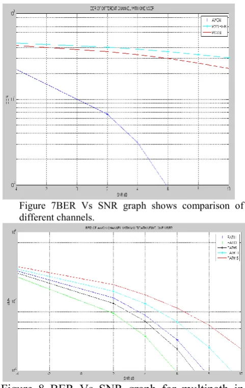
7. RESULTS AND DISCUSSION
BER of DS-CDMA with Rake Receiver measured through MATAL Simulink Model using BPSK in baseband. CDMA is technology for digital transmission of radio signal in telecommunication systems. In this technology, multiple users can transmit the data simultaneously in a channel using same frequency. Each user is assigned a distinguished code for transmission; the data was transmitted to receiver in AWGN and Fading channels. During transmission, SNR values of signal changes to calculate BER value to plot BER vs. SNR graph in AWGN and Fading channel.
SNR in dB
BER in AWGN (%)
BER in Rayleigh
(%)
BER in Rician (%)
-10 0.3529 0.4762 0.4621 -4 0.2231 0.4515 0.4252 2 0.0673 0.4065 0.3603 4 0.0313 0.3845 0.3305 6 0.0094 0.3593 0.3002 8 0.00145 0.3325 0.2691 10 0.000125 0.3052 0.2393
Table 1 BER in AWGN, Rayleigh and Rician fading channels over BPSK.
SNR Only USER 1
present USER 1 & 2 present USER 1, 2 &3 present
-10 0.3529 0.3526 0.3525
-4 0.2231 0.225 0.2268
2 0.0673 0.0704 0.0730
4 0.0313 0.0356 0.03731
6 0.0094 0.0121 0.0136
8 0.0014 0.0026 0.0046
10 0.0001 0.0002 0.0006
Table 2 BER for AWGN Channel with Multipath and Rake fingers 3.
I. CONCLUSIONS
This paper presents a DS-CDMA cellular system using theRAKE receiver. Rake receiver is used for CDMA technique rather than conventional CDMA with matched filter. The added advantage of this technique is to minimize the BER with maximize SNR.
Page | 632
Adding multiuser degrade the performance of system. BER increases as number of user increases, it has been observed due to adding user causes interference which is distributed (share) among existing users equally and SNR decreases slightly. it has observed by simulink model with three users.
APPENDIX
Results that have been observed are shown below
Figure 7BER Vs SNR graph shows comparison of different channels.
Figure 8 BER Vs SNR graph for multipath in AWGN channel.
REFERENCES
[1] J. S Proakis, “Digital Communications”, McGraw-Hill, New- York, 1995.
[2] Tommi Heikkila, Rake Receiver, Postgraduate Course in Radio Communications Autumn 2004.
[3] Diversity Techniques in Wireless Communication Systems, 16:332:546 Wireless Communication Technologies Spring 2005.
[4] Wideband DS-CDMA for Next-Generation Mobile Communications Systems, IEEE Communication Magazine September, 1998.
[5] IEEE standard for wireless LAN: Medium Access Control and Physical Layer Specification, P802.11, January 1999.
[6] Mohammaed Slim Alouini and Andrea J. Goldsmith “ Capacity of Rayleigh fading channels under different Adaptive Transmission and Diversity combining Techniques”, IEEE Transactions on Vehicular Technology, Vol. 48, No. 4, July 1999.
[7] Gary Breed, High Frequency Electronics, 2003 Summit, Technical Media LLC “Bit Error Rate: Fundamental Concepts and measurement issues”.
[8] Fumiyaki Adachi, “error Rate Analysis of Differentially Encoded and detected 16-APSK under Rician fading”, IEEE Transactions on Vehicular Technology, Vol. 45, No. 1, February 1996.
[9] Jiho Ryu, Jeong Keun Lee, Sung-Ju Lee and Taekyoung Kwon, “Revamping the IEEE 802.11a PHY Simulation Models”, MSWim‟
08, October 27-31, 2008, Vancouver, BC, Canada.
[10] A. Alimohammad, S.F.Fard, B.F.Cockburn and C.Schlegal, “Compact Rayleigh and Rician fading simulation based on random walk processes”, IET Communications, 2009, Vol. 3, Issue 8, pp 1333-1342.
[11] Yahong Rosa Zheng and Chengshan Xiao, “Simulation models with correct statistical properties for Rayleigh fading channels”, IEEE Transactions on communications, Vol. 51, No. 6, June 2003.
[12] “Quadrature Amplitude Modulation”, digital Modulation Techniques”
www.digitalmodulation.net/qam.html
Page | 633
[14] James E. Gilpy, Transcript International Inc., August 2003, “Bit Error Rate Simulation using Matlab”
[15] A. Sudhir Babu “Evaluation of BER for AWGN, Rayleigh and Rician Fading Channels under Various Modulation Schemes”,
International Journal of Computer Applications (0975 – 8887) Volume 26– No.9, July 2011
[16] “Performance and Analysis of DS-CDMA Rake Receiver” by Y Mohan Reddy, M Nanda Kumar, K Manjunath, International Journal of Advanced Research in Computer Engineering & Technology, Volume 1, Issue 3, May 2012
[17] “Performance analysis of DS-CDMA rake receiver over AWGN channel for wireless communications” by N.Anand Ratnesh, K.Balaji, J.V.Suresh, L.Yogesh, International Journal of Modern Engineering Research (IJMER) Vol.2, Issue.3, May-June 2012 pp-859-863
[18] Performance and Analysis of DS-CDMA Rake Receiver and Analyzing the BER Performance in Presence of Nonlinear Distortion in DS-CDMA System by Y Mohan Reddy, K Manjunath, K Yogaprasad. “International Journal of Advanced Research in Computer Science and Electronics Engineering Volume 1, Issue 5, July 2012”
[19] Performance Evaluation of Rake and Pre-Rake Receiver for a Wireless DS-CDMA System. “International Journal of Engineering and Technology Volume 2 No. 7, July, 2012” [20] Improved BER Detection of CDMA IS95A
Forward Traffic Channel.” International Journal of Computer Information Systems, Vol. 4, No.4, 2012”
[21] BER Improvement of DS-CDMA with Rake Receiver Using Multipath Fading Channel .
Mr. Khaire Ganesh B. Received B E degree in
Electronics &
Telecommunication from university of Pune, currently
he is doing M Ein Dgital System from Amrutvahini College of Engineering, Sangamner. His area of interest is wireless communication.