ISSN (Print) : 2320 – 3765 ISSN (Online): 2278 – 8875
I
nternational
J
ournal of
A
dvanced
R
esearch in
E
lectrical,
E
lectronics and
I
nstrumentation
E
ngineering
(An ISO 3297: 2007 Certified Organization)
Vol. 4, Issue 4, April 2015
Simulation and Magnetic Analysis of Switched
Reluctance Motor with Various Rotor Pole
Shapes Using Finite Element Method
Jisha Kuruvila
1, Abhijith P
2, Mathew Jacob
3, Ramesh Babu
4, Swathy Mohan V
5, Varun Jo Abu
6Assistant Professor, Dept. of Electrical Engineering, M A College of Engineering, Kothamangalam, India1
UG Student, Dept. of Electrical Engineering, M A College of Engineering, Kothamangalam, India2
UG Student, Dept. of Electrical Engineering, M A College of Engineering, Kothamangalam, India3
UG Student, Dept. of Electrical Engineering, M A College of Engineering, Kothamangalam, India4
UG Student, Dept. of Electrical Engineering, M A College of Engineering, Kothamangalam, India5
UG Student, Dept. of Electrical Engineering, M A College of Engineering, Kothamangalam, India6
ABSTRACT: Optimum design of Switched Reluctance Motor (SRM) and it control circuits require a knowledge of its parameters, such as inductance, flux linkage and torque. A model of SRM has been developed and analysed with COMSOL Workbench. The variation of flux density and directional force with respect to stator position for different rotor pole shapes has been analysed. From the results of analysis the variation of flux density and directional force of the models can be predicted. This study can be used for further modification of physical size of the motor to get more
improved performance and to manufacture the SRM
.
KEYWORDS: Switched Reluctance Motor, COMSOL, Finite element analysis, Flux density, Torque.
I.INTRODUCTION
Recently, many industrial application fields are adopting the switched reluctance motor (SRM) for its number of advantages such as easy control, simple structure and low cost. In particular, the SRM is mainly applied to wind turbines and high-speed equipment because it can be operated in a wide speed range. To complement the existing permanent magnet machine with the issue of reliability and price, the SRM has been applied especially in the field of wind power. The theory of motor with variable reluctance has been started to be used since 1980’s for the variable or adjusted speed application and the use of these motors started to be very popular in engineering applications. The simulation and experimental investigations of the electromagnetic field distribution are one of critical topics for developing electromagnetic products. Although the FEM was a time-consuming and difficult method in the past, with contemporary high speed computers with large memory, the method can be used properly in analysis of electric machines. In addition, various commercial finite-element packages COMSOL Workbench have been so far developed for this purpose.
ISSN (Print) : 2320 – 3765 ISSN (Online): 2278 – 8875
I
nternational
J
ournal of
A
dvanced
R
esearch in
E
lectrical,
E
lectronics and
I
nstrumentation
E
ngineering
(An ISO 3297: 2007 Certified Organization)
Vol. 4, Issue 4, April 2015
RMxprt. The efficiency of the motor with the proposed slot is significantly improved. Da-Woon Choi et.al [3] describes the simulation of a 6/4 SRM. All simulations are completely documented by their block diagram and corresponding special matlab functions and parameters quickly develop its model to the reader. Based on the developed model, simulation studies are performed and compared with measured phase currents either for hysteresis and voltage control strategies to validate the model. Dr. M. Balaji et.al [4] deals with the design of wind generator with the aim of reducing the torque ripple. Initially generator is mathematically designed and then simulation is performed in order to obtain the optimum design. Saphir Faid et.al [5] deals with the design of switched reluctance motor based on the aim of reducing the torque ripple. This paper presents a comparative study on torque ripple minimization in SRM with modified pole shapes such as stator pole taper, stator pole face with non-uniform air gap and pole shoe attached to rotor pole. Further this paper presents a detailed sensitivity analysis of the effect of different geometrical parameters that alter the pole face shapes on the performance of SRM. The analysis is performed using finite-element method considering average torque and torque ripple as performance parameters
II.PARAMETRIC SIMULATION MODEL
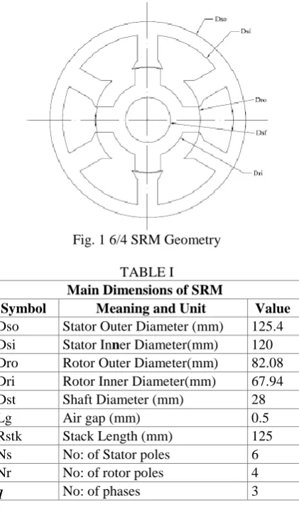
In order to analyze the SRM by COMSOL Workbench, the geometrical model of the motor should be plotted at first and appropriate materials are assigned to different regions. With a reasonable approximate, the whole geometric structure of SRM can be generated by geometric parameters, including radius of different parts of the motor, stator and rotor pole arc lengths. The values of physical changes of SRM with 6/4 pole are shown in the table 1. The 2D cross section, size variables and values of 6/4 SRM are given is shown in fig. 1. More geometrical models are plotted varying the rotor parameters keeping the stator shape constant as shown in fig. 2.
Fig. 1 6/4 SRM Geometry
TABLE I
Main Dimensions of SRM
Symbol Meaning and Unit Value
Dso Stator Outer Diameter (mm) 125.4
Dsi Stator Inner Diameter(mm) 120
Dro Rotor Outer Diameter(mm) 82.08
Dri Rotor Inner Diameter(mm) 67.94
Dst Shaft Diameter (mm) 28
Lg Air gap (mm) 0.5
Rstk Stack Length (mm) 125
Ns No: of Stator poles 6
Nr No: of rotor poles 4
ISSN (Print) : 2320 – 3765 ISSN (Online): 2278 – 8875
I
nternational
J
ournal of
A
dvanced
R
esearch in
E
lectrical,
E
lectronics and
I
nstrumentation
E
ngineering
(An ISO 3297: 2007 Certified Organization)
Vol. 4, Issue 4, April 2015
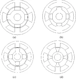
So as to perform a comparative analysis of Switched Reluctance Motor, four different SRM structures are drawn keeping the above mentioned dimensions constant and varying the rotor shapes as shown in figs. 2.
(a) (b)
(c) (d)
Fig 2. Configurations of SRM
III. FINITE ELEMENT ANALYSIS
The 3D Finite Element Method (FEM) Analysis of SR motor is carried out with help of COMSOL workbench. The simulation and experimental investigations of the electromagnetic field distribution of SR motor are analyzed with help of what-if analysis for different rotor shapes under constant stator shapes and excitation. Torque characteristic is one of the most important electromagnetic characteristics of SRM, which can be used in calculation of average torque and torque ripple. Direct calculation of torque in SRM with analytical method is impossible. Usually, torque is derived from the flux-linkage characteristic of phase. However, analytical methods cannot model precisely the region in where the stator and rotor poles begin to overlap, so prediction of the static torque is faced with a problem in this region. Using COMSOL Workbench, it is possible to predict the torque directly. The torque is computed in COMSOL using the Maxwell’s stress tensor method given by
T =
ʃ
B (r-ro) x (n1 T2) dSwhere ro is the point on the axis of rotation and n is the unit vector to the surface of S.
IV. SIMULATION OUTPUTS
The cadd drawings are imported to the software COMSOL and simulation procedures are performed so as to obtain the static and transient characteristics.
1. Static characteristics
ISSN (Print) : 2320 – 3765 ISSN (Online): 2278 – 8875
I
nternational
J
ournal of
A
dvanced
R
esearch in
E
lectrical,
E
lectronics and
I
nstrumentation
E
ngineering
(An ISO 3297: 2007 Certified Organization)
Vol. 4, Issue 4, April 2015
along with the flux linkage. The variation in magnitude of flux density can be observed. The scale of flux density is given in the characteristics and based on this; comparison of flux density of four SRM structures can be obtained. Referring to figure 3(a) V1, V6 and V4, V3 winding slots are excited therefore teeth A and D get magnetized. So rotor will align in minimum reluctance position.
Fig 3. Static characteristics of fig. 2(a)
2. Transient characteristics
Transient characteristics clearly explain the working of SRM. Periodic variation of excitation is done and rotor tries to align in the max flux density region (minimum reluctance region). The variation of flux density as per the change in excitation and the movement of rotor towards the maximum flux density position can be observed.
V. RESULT AND DISCUSSION
The torque characteristics of SRM depends on the stator rotor pole overlap angle, pole geometry, material properties, number of poles, and number of phases. The torque output and torque ripple of SRM are sensitive to stator and rotor pole arcs. Average torque and torque ripple are considered as performance measures while determining optimum pole arc. From the results of simulation, the SRM structure giving the maximum torque output and minimum torque ripple is find out giving consideration to copper loss. This chapter focuses on computational intelligence based optimization techniques combined with static finite element simulation for determination of optimal pole shapes of SRM.
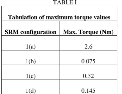
1. Analysis of Torque characteristics
TABLE I
Tabulation of maximum torque values
SRM configuration Max. Torque (Nm)
1(a) 2.6
1(b) 0.075
1(c) 0.32
1(d) 0.145
ISSN (Print) : 2320 – 3765 ISSN (Online): 2278 – 8875
I
nternational
J
ournal of
A
dvanced
R
esearch in
E
lectrical,
E
lectronics and
I
nstrumentation
E
ngineering
(An ISO 3297: 2007 Certified Organization)
Vol. 4, Issue 4, April 2015
Fig. 4(a) Torque characteristics of fig. 1(a)
Fig 4(a) shows the torque output of fig 1(a). The maximum torque is obtained as 2.6 Nm.
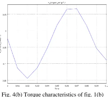
Fig. 4(b) Torque characteristics of fig. 1(b)
Fig 4(b) shows the torque output of fig 1(b). The maximum torque is obtained as 0.075 Nm. The maximum torque value is found to be reduced and this is due to the fringing effect caused due to the change in the rotor shape.
Fig. 4(c) Torque characteristics of fig. 1(c)
ISSN (Print) : 2320 – 3765 ISSN (Online): 2278 – 8875
I
nternational
J
ournal of
A
dvanced
R
esearch in
E
lectrical,
E
lectronics and
I
nstrumentation
E
ngineering
(An ISO 3297: 2007 Certified Organization)
Vol. 4, Issue 4, April 2015
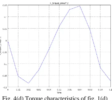
Fig. 4(d) Torque characteristics of fig. 1(d)
Fig 4(d) shows the torque output of fig 1(d). The maximum torque is obtained as 0.145 Nm
Max torque has been observed for the first structure Fig. 1(a) and is found to be 2.56 Nm. Maximum torque values been inferred from the torque curves comparison of which gives the best rotor structure which is expected to have max flux linkage and minimum fringing effect. This study can be used for further modification of physical size of the motor to get more improved performance and to manufacture the SRM.
VI.CONCLUSION
In this paper three-dimensional magnetic analysis of a switched reluctance motor has been given. From the results of analysis the variation of flux density and torque of four different srm models have been predicted. This study can be used for further modification of physical size of the motor to get more improved performance and to manufacture the SRM.
REFERENCES
[1] M Sundaram, P Navaneethan and M Vasanthakumar, “Magnetic Analysis and Comparison of Switched Reluctance Motors with Different Stator Pole Shapes Using a 3D Finite Element Method,” International Conference on control, automation, communication and energy conservation, no. 18, pp. 1-4, June 2003.
[2] M Sundaram and P Navaneethan, “On the Influence of Stator Slot shape on the Energy Conservation Associated with the Submersible Induction Motors,” American Journal of Applied Sciences, vol. 32, no. 18, pp. 393-399, 2011.
[3] F Soares and J Coasta Branco, “Simulation of a 6/4 switched reluctance motor based on matlab/simulink environment,” IEEE transactions on aerospace and electronic systems, vol. 37, no. 3, pp. 989-1008, July 2007.
[4] Da-Woon Choi, Sang-In Byun, and Yun-Hyun Cho, “A Study on the Maximum Power Control Method of Switched Reluctance Generator for Wind Turbine,” IEEE transactions on magnetics, vol. 50, no. 1, pp. 201-210, January 2014.
[5] Dr. M. Balaji, Dr. S. Ramkumar, and Dr. V. Kamaraj, “Sensitivity Analysis of Geometrical Parameters of a Switched Reluctance Motor with Modified Pole Shapes,” J Electr Eng Technol, vol. 8, no. 1, pp. 1983-1997, 2011.
[6] Saphir Faid, Patrick Debal , and Steven Bervoets, “Development of a Switched Reluctance Motor for Automotive Traction Applications,” The 25th World Battery, Hybrid and Fuel Cell Electric Vehicle Symposium & Exhibition, vol. 1, no. 5-9, 2013.