ISSN (Print) : 2320 – 3765 ISSN (Online): 2278 – 8875
I
nternational
J
ournal of
A
dvanced
R
esearch in
E
lectrical,
E
lectronics and
I
nstrumentation
E
ngineering
(An ISO 3297: 2007 Certified Organization) Vol. 5, Issue 3, March 2016
PLC Based Industrial Timer Controller for
Multiple Machines
Dattu B.Shinde1, Reshma S.Waghamare2, Vijayalaxmi C.Kalal3
UG Student, Dept. of E&TC, S.M.S.M.P.I.T.R, Akluj, Maharashtra, India1& 2
Assistant Professor, Dept. of E&TC, S.M.S.M.P.I.T.R, Akluj, Maharashtra, India3
ABSTRACT: An automated machine is increased in this globalised world. This project outlines the timer controller for multiple machines. Over the years, the demand increases for high quality, greater efficiency and automatic machines. In this project, the main application is control of Oven operation and movement of conveyer using PLC. The initial phase of the project focuses on passing the inputs to the oven at a required temperature, so as to constantly maintain a particular temperature in the ovens. The project mainly focuses on level, pressure and flow control at the various stages of the project plant. Thus the temperature in the ovens is constantly monitored and brought to a constant temperature as required by the project plant. The automation is further enhanced by constant monitoring using SCADA screen which is connected to the PLC by means of communication cable. By means of tag values set to various variable in SCADA the entire process is controlled as required. This project has proved to be very efficient practically as the need for automation grows day by day. SCADA (Supervisory Control and Data Acquisition) system monitors the plant and helps reduce the errors caused by humans. While the SCADA is used to monitor the system, PLC (Programmable Logic Controller) is also used for the internal storage of instruction for implementing function such as logic, sequencing, timing, counting and arithmetic to control through digital or analog input/output modules and various types of machines processes. Systems are used to monitor and control a plant or equipment in industries such as telecommunications, water and waste control, energy, oil and gas refining and transportation.
KEYWORDS: PLC, SCADA, Automation, Ladder diagram.
I.INTRODUCTION
Originally PLCs were designed as a replacement for hard-wired relay and timer logic control systems. PLCs have the great advantage that it is possible to modify a control system without having to rewrite the connections to the input and output devices, the only requirement being that an operator has key in a different set of instruction. The result is a flexible system which can be used to control systems which vary quite widely in their nature and complexity.
A.PLC SYSTEM
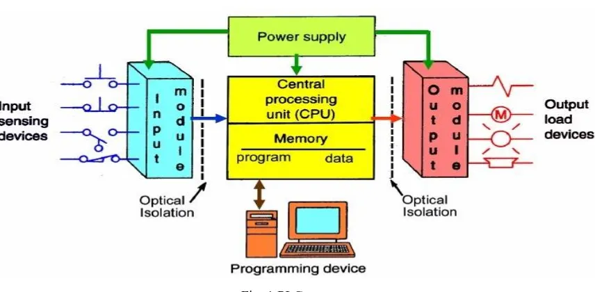
Programmable Logic Controller (PLC) is a small computer used for automation of real-world processes, such as control of machinery on factory assembly lines. The PLC usually uses a microprocessor. The program can often control complex sequencing and is often written by engineers. The program is stored in battery-backed memory and/or EEPROMs. Unlike general-purpose computers, the PLC is packaged and designed for extended temperature ranges, dirty or dusty conditions, immunity to electrical noise, and is mechanically more rugged and resistant to vibration and impact. By implementing this project we decreases man power, thus increase in production of the industry.
Fig. 1 PLC system
The basic motivation for our project is to control the industrial timer in multiple machines. Over the years the demand for high quality, greater efficiency and automated machines has increased in the industrial sector of power plants. In this project we are using PLC to control the temperature and movement of multiple ovens and conveyer.
II. SYSTEM ARCHITECTURE
This project gives the efficient way of automating the conveyor using delta series PLC along with SCADA for high reliability and fast operation without delay. It consists of hardware and software modules to identify the conveyor faults. The system consists of many functional units such as different types of detectors, temperature sensor, emergency stop etc. Figure 2.1shows system block diagram representation of system. Here delta series PLC plays vital role i.e. it is heart of this system. The PLC is burnt with program that is necessary to control the sensors and relays interfaced to it. The interfaced units are controlled by the PLC in an efficient and faster manner, thus providing the system to be reliable than the existing ones.
ISSN (Print) : 2320 – 3765 ISSN (Online): 2278 – 8875
I
nternational
J
ournal of
A
dvanced
R
esearch in
E
lectrical,
E
lectronics and
I
nstrumentation
E
ngineering
(An ISO 3297: 2007 Certified Organization) Vol. 5, Issue 3, March 2016
III. COMPONENTS OF PROPOSED SYSTEM
A. DELTA SERIES PLC
Programmable logic controller (PLC) is a control system using electronic operations. It’s easy storing procedures, handy extending principles, functions of sequential/position control, timed counting and input/output control are widely applied to the field of industrial automation control. Delta's DVP series programmable logic controllers offer high-speed, stable and highly reliable applications in all kinds of industrial automation machines. In addition to fast logic operation, bountiful instructions and multiple function cards, the cost-effective DVP-PLC also supports various communication protocols, connecting Delta's AC motor drive, servo, and human machine interface and temperature controller through the industrial network in to a complete “Delta Solution” for all users.
B. LM35
The LM35 series are precision integrated-circuit temperature sensors, whose output voltage is linearly proportional to the Celsius (Centigrade) temperature. It can be used with single power supplies, or with plus and minus supplies. As it
draws only 60μA from its supply, it has very low self-heating, less than 0.1°C in still air. The LM35 is rated to operate over a −55° to +150°C temperature range. Once it reaches the specified temperature range, which is meant for fire
Accident, the belt conveyor will give indication and stopped immediately and fire is extinguished, thus protecting fire accidents without time delay.
C. START BUTTON
To start the conveyor, the operator presses the Start button. This provides power momentarily to a relay coil. As the relay coil is energized, it closes its normally-open contact so that power is provided through the normally-open relay contact to both the relay coil and the conveyor. As long as the relay is energized, the circuit is complete and power is provided to the conveyor. This button is must for safe and reliable operation of conveyor.
D. EMERGENCY STOP
Emergency stop (E-Stop) buttons are an important safety component of many electrical circuits, especially those that control hazardous equipment such as gas pumps, moving machinery, saws, mills, and cutting tools, conveyor belts, and many other types of equipment. They are designed to allow an operator or bystander to stop the equipment in a hurry.
E. CONVEYOR
Conveyors are durable and reliable components used in automated distribution and warehousing. In combination with computer controlled pallet handling equipment this allows for more efficient retail wholesale and manufacturing distribution. It is considered a labour saving system that allows large volumes to move rapidly through a process, allowing companies to ship or receive higher volumes with smaller storage space and with less labour expense. These are used for shifting of coal from one place to other places.
Once coal is extracted from underneath the ground, there are various options available when it comes to transporting it to where it needs to go. After it's arrived at the processing facility or other commercial/industrial area, it's time to unload it onto a conveyor. Conveyors are also used to transport material into processing equipment and back out again, and thus optimize productivity.
IV. WORKING & OBJECTIVES
A.WORKING
Fig.3 PLC based industrial timer control in multiple ovens
From the above fig, it shows that the number of ovens is connected to the conveyer which is connected to the PLC. Here the mud is collected and is mixed with a special liquid. Then it is transmitted to the multiple ovens with the conveyer with their specific time and temperature. Here the temperature of the conveyer is controlled by the PLC as shown in above fig. in this way our project is works.
ISSN (Print) : 2320 – 3765 ISSN (Online): 2278 – 8875
I
nternational
J
ournal of
A
dvanced
R
esearch in
E
lectrical,
E
lectronics and
I
nstrumentation
E
ngineering
(An ISO 3297: 2007 Certified Organization) Vol. 5, Issue 3, March 2016
C.THE SOFTWARE DEVELOPMENT
The software part deals in programming the PLC. In the present work we have used Codesys software to write a program for PLC. The project also uses visual basic for interacting with the user.
D. LADDER DIAGRAM
PLC programs are typically written in a special application on a personal computer, and then downloaded by a direct-connection cable or over a network to the PLC. The program is stored in the PLC either in battery-backed-up RAM or some other non-volatile flash memory. Often, a single PLC can be programmed to replace thousands of relays Ladder logic is a programming language that represents a program by a graphical diagram based on the circuit diagrams of relay logic hardware. It was primarily used to develop software for programmable logic controllers (PLCs) used in industrial control applications. The name is based on the observation that programs in this language resemble ladders, with two vertical rails and a series of horizontal rungs between them. Fig. 4 shows simple ladder logic of the project.
Fig. 4 Ladder diagram of our project
V. RESULT AND CONCLUSION
A. RESULT
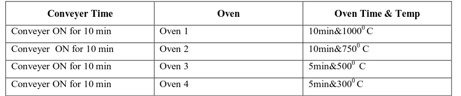
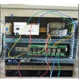
The result of this project is to control industrial timer in multiple ovens using PLC. In this project we have controlled the timing of the each ovens with different temperature and also, controlled the timing of the conveyer to carry input material as shown in table 1 with hardware implementation of the project in fig. 5.
Table 1 On timing of the conveyers with temperatures set
Conveyer Time Oven Oven Time & Temp
Conveyer ON for 10 min Oven 1 10min&10000 C
Conveyer ON for 10 min Oven 2 10min&7500 C
Conveyer ON for 10 min Oven 3 5min&5000 C
Fig. 5 Hardware Implementation of Project
B. CONCLUSION
By studying this project along with the existing system, we can conclude that this project helps to improve the output accuracy with greater efficiency by reducing the man power. As the existing systems using microcontroller increases the complexity as well as the wiring required for the system is more also we can’t rewrite the program in the microcontroller when it is already burn by the program. As we are using PLC which is reprogrammable with security and easy to use as compared to relay logic we can control multiple machines with multiple parameters with a single PLC.
REFERENCES
[1] Albert W.L. Yao, C.H. Ku, “Developing a PC-based automated monitoring and control power systems”, Electric Power Systems Research, Vol. 64, 2003, pp. 129- 136.
[2] Limin Cai. “Temperature Measurement and Control System Based on Embedded Web”, Computer and Information Science, Vol.2.No.2, May. [3] Darmstadt, “Conveyor systems”, in Proceedings of the 1st IFAC-Conference on Mechatronic Systems.” pp. 693-698, 2000.
[4] Shashank Lingappa M, V. Bongale, “PLC Controlled Low Cost Automatic Packing Machine”, ISSN 2250-3234 Volume 4, Number 7 (2014), pp. 803-811
[5] Kevin Collins,“PLC Programming for Industrial Automation”.