ISSN (Print) : 2320 – 3765 ISSN (Online): 2278 – 8875
I
nternational
J
ournal of
A
dvanced
R
esearch in
E
lectrical,
E
lectronics and
I
nstrumentation
E
ngineering
(A High Impact Factor, Monthly, Peer Reviewed Journal)
Website: www.ijareeie.com
Vol. 6, Issue 10, October 2017
A Very High Power Three Phase 15 Level
H-Bridge Inverter for Heat Treatment
L. Pattathu Rani1, Rajat Kumar Dwibedi2
Assistant Professor, Dept. of EEE, Jeppiaar Institute of Technology, Chennai, Tamilnadu, India1 Assistant Professor, Dept. of ECE, Jeppiaar SRR Engineering College, Chennai, Tamilnadu, India2
ABSTRACT: Heat treatment is a metal working processes used to alter the physical and sometimes chemical properties
of a material. It also involves the use of heating or cooling, normally to extreme temperatures, to achieve a desired results such as hardening or softening of a material. This technique includes annealing, case hardening, precipitation strengthening, tempering, normalizing and quenching. The heat depth is controlled by the system output frequency; Lower frequencies are suitable for the deeper heating while surface heating needs high frequencies.15 level cascaded H-bridge multilevel inverter is used for heat treatment in steel industries because of output voltage levels with minimal harmonic distortion, usage of minimum number of components, low switching losses, eliminate the problems of equal voltage sharing for series connected devices by connecting H bridge power cells in cascade to produce high ac voltage.The results are verified both by hardware and software.
KEYWORDS: THD(Total Harmonic Distortion), MTI(Multi Level Inverter),
I.INTRODUCTION
Cascaded H Bridge multi Level Inverter is one of the most important inverters nowadays. They can generate output voltages with extremely low distortion and lower order harmonics. They draw input current with very low distortion. In addition, using sophisticated modulation types of methods, CM voltages can be eliminated. They can operate with a less switching frequency. In this topology Cascaded H-Bridge fifteen level Inverter is used. Cascaded H-bridge multilevel converters have been applied where high power and power quality are essential, for example, static synchronous compensators active filter and reactive power compensation applications, photo voltaic power conversion, uninterruptable power supplies, and magnetic resonance imaging. The number of phase voltage levels at the converter terminals is 2N+1, where N is the number of cells or dc link voltages. In this type of inverter the diode and the capacitors are eliminated and DC sources or voltage cells are connected across each H-Bridge cells. So the pre charging of the capacitor problem is eliminated and the voltage balancing problem also eliminated. It is composed of multiple units of single-phase H bridge power cells. The cascaded H bridge multilevel inverter requires a number of isolated dc supplies, each of which feeds a H-bridge power cell.
II. MULTILEVEL INVERTER
ISSN (Print) : 2320 – 3765 ISSN (Online): 2278 – 8875
I
nternational
J
ournal of
A
dvanced
R
esearch in
E
lectrical,
E
lectronics and
I
nstrumentation
E
ngineering
(A High Impact Factor, Monthly, Peer Reviewed Journal)
Website: www.ijareeie.com
Vol. 6, Issue 10, October 2017
system. Multi-level inverters are the modification of basic bridge inverters. They are normally connected in series to form stacks of level.
A multilevel inverter can be defined as a device that is capable to produce a stepped waveform. The generalized stepped waveform is shown in figure 1.
Fig.1 Generalized stepped waveform
III. CASCADED MULTILEVEL INVERTER
The modularity of this structure allows easier maintenance and provides a very convenient way to add redundancy into the system. The multilevel inverter using cascaded-inverter with separate DC sources synthesizes a desired voltage from several independent sources of dc voltages, which may be obtained from batteries, fuel cells, or solar cells. This configuration recently becomes very popular in ac power supply and adjustable speed drive applications. This new inverter can avoid extra clamping diodes or voltage balancing capacitors.
Multilevel converters are increasingly being considered for high power applications because of their ability to operate at higher output voltages while producing lower levels of harmonic components in the switched output voltages. Two well known multilevel converter topologies are the Neutral Point Clamped (NPC) Inverter and cascaded inverters. To operate a cascade multilevel inverter using a single DC source, it is proposed to use capacitors as the DC sources for all but the first source. Consider a simple cascade multilevel inverter with two H-bridges as shown in Fig.2 Single-phase structure of a multilevel cascaded H-bridges inverter.
Fig.2 Single-phase structure of a multilevel cascaded H-bridges inverter
ISSN (Print) : 2320 – 3765 ISSN (Online): 2278 – 8875
I
nternational
J
ournal of
A
dvanced
R
esearch in
E
lectrical,
E
lectronics and
I
nstrumentation
E
ngineering
(A High Impact Factor, Monthly, Peer Reviewed Journal)
Website: www.ijareeie.com
Vol. 6, Issue 10, October 2017
multilevel inverter is v(t)=v1(t)+v2(t) By opening and closing the switches of H1 appropriately, the output voltage v1 can be made equal to - Vdc , 0, or Vdc while the output voltage of H2 can be made equal to - Vdc/2, 0, or Vdc/2 by opening and closing its switches appropriately.
The NPC inverter uses a series string of capacitors to subdivide a single high voltage DC bus into the required number of voltage levels, and each phase leg output can be switched to any one of these levels. In comparison the Cascaded inverter uses the series connection of a number of full bridge inverters to construct each multilevel phase leg. The main disadvantage of this topology is that each full bridge inverter requires its own isolated DC supply, which is generally achieved using a multi winding low frequency transformer or high frequency DC to DC converters. The need for these DC supplies has generally restricted the use of Cascaded inverters to the high power range of operation where several output voltage levels are needed and the Neutral Point Voltage balancing problem for a NPC inverter complicates the use of that structure. A further attraction of the Cascaded inverter is that the control and protection requirements of each bridge are modular.
More recently, a new inverter topology (derived from the Cascaded structure) called the Hybrid inverter has been proposed, where the cascaded series inverters have different internal DC bus voltages, use different switching devices (IGCT’s and IGBT’s) and are modulated quite differently.
IV.PROPOSED SYSTEM
The proposed system is a solar powered high power three phase 15 level inverter for heat treatment in steel industries. The 15 level inverter requires three phase DC input fed from the solar panel. The elementary concept of a multilevel inverter to achieve higher power is to use a series of power semiconductor switches with several lower voltage dc sources to perform the power conversion by synthesizing a staircase voltage waveform. The commutation of the power switches aggregate these multiple dc sources in order to achieve high voltage at output. This power electronic circuit requires a gate pulse for functioning. However, the rated voltage of the power semiconductor switches depends only upon the rating of dc voltage sources to which they are connected. Three phase H-bridge multilevel inverter is like three single phase inverter and three H-bridge inverter are connected together. Therefore the maximum number of line voltage is 2m+1, where m is a number of phases.
The proposed block diagram is a solar powered cascaded 15 level H bridge inverter used for heat treatment in steel industries. DC supply is taken from the solar panel through Maximum Power Point Tracking (MPPT) charge controller. This battery provides the DC supply for the cascaded multilevel inverter. And the output from the H bridge inverter is fed to the load that is the heat treatment of the steel.
Fig.3 Proposed block diagram.
A. PROPOSED CIRCUIT DIAGRAM
ISSN (Print) : 2320 – 3765 ISSN (Online): 2278 – 8875
I
nternational
J
ournal of
A
dvanced
R
esearch in
E
lectrical,
E
lectronics and
I
nstrumentation
E
ngineering
(A High Impact Factor, Monthly, Peer Reviewed Journal)
Website: www.ijareeie.com
Vol. 6, Issue 10, October 2017
charged with the MPPT. This circuit contains 36 number of switches. These switches are connected in H bridge shape. Each H bridge cell may have positive, negative or zero voltage. Final output voltage is the sum of all H-bridge cell voltages and is symmetric with respect to neutral point, so the number of voltage levels is odd. The cascaded H-bridges multi level inverter introduces the idea of using Separate DC Sources (SDCSs) to produce an AC voltage waveform. Each H-bridge inverter is connected to its own DC source Vdc. By cascading the AC outputs of each H-bridge inverter, an AC voltage waveform is produced. By closing the appropriate switches, each H-bridge inverter can produce three different voltages: Vdc, 0 and -Vdc. It is also possible to modularize circuit layout and packaging because each level has the same structure, and there are no extra clamping diodes or voltage balancing capacitors. Circuit consist of 36 number of switches, separate dc sources for each H bridges and the output is given to the load.
Fig.4 Proposed circuit diagram
Each H-bridge inverter is connected to its own DC source Vdc. By cascading the AC outputs of each H-bridge inverter, an AC voltage waveform is produced. By closing the appropriate switches, each H-bridge inverter can produce three different voltages: Vdc, 0 and -Vdc. It is also possible to modularize circuit layout and packaging because each level has the same structure, and there are no extra clamping diodes or voltage balancing capacitors. The number of switches is reduced using the new topology. Circuit consist of 12 number of switches, separate dc sources for each H bridges and the output is given to the load. The working of this CHBMLI is operated in different modes. Mainly 8 modes of operation only for the positive half cycle and eight modes of operation for the negative half cycle. Here shows the eight modes in the positive half cycle alone. The three voltage sources has three different low level voltages V1,V2,V3.These three voltages passes through the cascaded H bridge MLI. So the output will have fifteen voltage levels. ie –Vdc/7, -2Vdc/7, -3Vdc/7, -4Vdc/7, -5Vdc/7, -6Vdc/7, - Vdc, 0 , Vdc/7, 2Vdc/7, 3Vdc/7, 4Vdc/7, 5Vdc/7, 6Vdc/7, Vdc Because each H bridges can produce three different voltage levels. Here these three voltages passes through the CHBMLI and produces fifteen level voltage as output. Only 12 numbers of switches are used and no need of diodes and capacitors. So the voltage balancing problem and pre charging of capacitor problem all are eliminated. The switching losses and power losses also reduced. Voltage stress to a particular switch can also be eliminated.
V.SIMULATION RESULTS
ISSN (Print) : 2320 – 3765 ISSN (Online): 2278 – 8875
I
nternational
J
ournal of
A
dvanced
R
esearch in
E
lectrical,
E
lectronics and
I
nstrumentation
E
ngineering
(A High Impact Factor, Monthly, Peer Reviewed Journal)
Website: www.ijareeie.com
Vol. 6, Issue 10, October 2017
does take into account the randomness and interdependence which characterize the behavior of your real-life business environment. Using simulation, one can include randomness through properly identified probability distributions taken directly from study data. For example, while the time needed to perform an assembly may average 10 minutes, special orders may take as many as 45 minutes to complete. A spreadsheet forces the use of average time, and will not be able to accurately capture the variability that exists in reality. Simulation also allows interdependence through arrival and service events, and tracks them individually.
The simulation models are obtained for various parts of the proposed system. Solar PV, MPPT converter, three phase inverter (Using Trapezoidal PWM, Sinusoidal PWM and Space Vector PWM) and the motor load are simulated in MATLAB and the results are analyzed.
A. VOLTAGE OUTPUT:
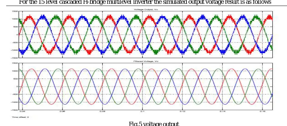
For the 15 level cascaded H-bridge multilevel inverter the simulated output voltage result is as follows
Fig.5 voltage output
B.VOLTAGE HARMONICS
ISSN (Print) : 2320 – 3765 ISSN (Online): 2278 – 8875
I
nternational
J
ournal of
A
dvanced
R
esearch in
E
lectrical,
E
lectronics and
I
nstrumentation
E
ngineering
(A High Impact Factor, Monthly, Peer Reviewed Journal)
Website: www.ijareeie.com
Vol. 6, Issue 10, October 2017
Fig.6 Voltage harmonics
C. CURRENT OUTPUT:
The simulated current output for the multilevel cascaded inverter is as follows.
ISSN (Print) : 2320 – 3765 ISSN (Online): 2278 – 8875
I
nternational
J
ournal of
A
dvanced
R
esearch in
E
lectrical,
E
lectronics and
I
nstrumentation
E
ngineering
(A High Impact Factor, Monthly, Peer Reviewed Journal)
Website: www.ijareeie.com
Vol. 6, Issue 10, October 2017
D.CURRENT HARMONICS
The FFT analysis is done and the current harmonics are determined by the simulation of 15 level cascaded multilevel inverter. And the current harmonics are represented below in a graph where the fundamental frequency 1140 at 50Hz and the total harmonics lies below 2%.
Fig.8.Current harmonics
E.SIMULATION RESULT OF 15 LEVEL INVERTER
ISSN (Print) : 2320 – 3765 ISSN (Online): 2278 – 8875
I
nternational
J
ournal of
A
dvanced
R
esearch in
E
lectrical,
E
lectronics and
I
nstrumentation
E
ngineering
(A High Impact Factor, Monthly, Peer Reviewed Journal)
Website: www.ijareeie.com
Vol. 6, Issue 10, October 2017
VI.HARDWARE RESULTS
The nine level multilevel inverter prototype model is shown in fig.10
Fig.10 Prototype model
A.HARDWARE OUTPUT
When switches (S3, S4) are ON the output voltage is as shown in fig.11 which is similar to the output of (S7, S8).
Fig.11 Switching states of (S3, S4).
ISSN (Print) : 2320 – 3765 ISSN (Online): 2278 – 8875
I
nternational
J
ournal of
A
dvanced
R
esearch in
E
lectrical,
E
lectronics and
I
nstrumentation
E
ngineering
(A High Impact Factor, Monthly, Peer Reviewed Journal)
Website: www.ijareeie.com
Vol. 6, Issue 10, October 2017
Fig.12 switching states of (S1, S2)
VII.CONCLUSION
This paper gives us the clear idea on the 15 level Cascaded H-Bridge multilevel inverter used for heat treatment in steel industries. It is observed from the output that the Total Harmonic Distortion (THD) is found to be least in the multilevel inverter. Thus the most efficient inverter for heat treatment that produces minimum harmonic distortion. The solar PV is also studied and is found to serve as an efficient source of power. Cascaded H-Bridge inverter finds its application in the steel industries for heat treatment. The hardware model built is found to be efficient in its application since its result did not deviate much from that of the simulation.
REFERENCES
[1] Kirubakaran. D, Rama Reddy. S “COMPARISON OF PARALLEL RESONANT INVERTER AND SERIES RESONANT INVERTER FOR INDUCTION HEATING”, Journal of electrical engineering.
[2] Nabil A Ahmed “Three-Phase High Frequency AC Conversion Circuit with Dual Mode PWM/PDM Control Strategy for High Power IH Applications”, World Academy of Science, Engineering and Technology International Journal of Electrical, Computer, Energetic, Electronic and Communication Engineering Vol:2, No:9, 2008
[3] M.S. Saravanan and R. Jeyabharath “Three Phase 15 Level Cascaded H-Bridges
Multilevel Inverter for Motor Drives ” American-Eurasian Journal of Scientific Research 11 (1): 21-27, 2016 ISSN 1818-6785 © IDOSI Publications, 2016
[4] Sanu Thomas P, Arun Xavier “Cascaded H Bridge Fifteen Level Inverter” International Journal of Engineering Research & Technology (IJERT) ISSN: 2278-0181 Vol. 4 Issue 09, September-2015.
[5] R.Anand, M.Kamatchi “A Fifteen Level Cascaded H-Bridge Multilevel
Inverter with Reduced Number of Switches” International Journal of Advanced Engineering Research and Science (IJAERS) Vol-2, Issue-11 , Nov- 2015] ISSN: 2349-6495.
[6] Jesline Naveena .A, Mr.B.Ramraj “An Advanced Topology for Cascade Multilevel Inverter Based on Developed H-Bridge” International Journal of Engineering Research and General Science Volume 2, Issue 6, October-November, 2014 ISSN 2091-2730.
[7] Hossein khoun jahan, Mohamad reza banaei, Saeedollah Talaei Mobaraki, “Combined H bridge Cells Cascaded Transformers Multilevel Inverter”
[8] O. Lucia, P. Maussion, E. J. Dede, and J. M. Burdio, “Induction heating technology and its applications: Past developments, current technology, and future challenges,” IEEE Trans. Ind. Electron., vol. 61, no. 5, pp. 2509–2520, May 2014.
[9] J. M. Burdio, L. A. Barragan, F. Monterde, D. Navarro, and J. Acero, “Asymmetrical voltage-cancellation control for full-bridge series resonant inverters,” IEEE Trans. Power Electron., vol. 19, no. 2, pp. 461–469, Mar. 2004.