MULTIFUNCTIONAL MEANDER LINE POLARIZER J.-C. Zhang, Y.-Z. Yin, and J.-P. Ma
National Laboratory of Antennas and Microwave Technology Xidian University
Xi’an, Shaanxi 710071, P. R. China
Abstract—A multifunctional meander line polarizer is described. The polarizer is capable of effecting conversions between linear and circular polarization and between left-hand and right-hand circular polarization. It can also cause arbitrary rotation of linear polarization, including converting a wave from horizontal polarization to vertical. The polarizer is analyzed by the spectral domain approach.
1. INTRODUCTION
Multilayered meander line polarizers are widely used due to their broadband, low insertion loss, and ease of manufacturing. In the past, meander line polarizers for linear to circular polarization (CP) conversion are discussed by many authors, and different methods for analyzing the meander line structures have been established [1–3]. In many cases, it is still necessary to have an antenna system with polarization diversity. In [4], a four layered meander line polarizer, converting horizontal polarization (HP) to vertical polarization (VP), is designed. In [5], an eight layered meander line polarizer is designed to effect arbitrary rotation of linear polarization (LP). In [6], a tunable polarizer is designed using photonic bandgap structures. In this letter, a multifunctional meander line polarizer, which can perform both of the above-mentioned conversion, as well as left-hand circular polarization (LHCP) to right-hand circular polarization (RHCP) conversion, is described.
2. THEORETICAL BACKGROUND OF MULTIFUNCTIONALITY
As shown in Fig. 1(b), the incident electric field Einc can be
decomposed into a horizontal componentEh and a vertical component
Ev. Obviously
Eh = Einccosφ (1)
Ev = Eincsinφ (2)
where φ is the angle of the meander line axis with respect to the incident electric field.
The mechanism of the meander line polarizer is that the field component horizontal to the meander line axis is delayed by the inductive character of the grating and the vertical component is advanced by the capacitive character of the grating, which results in a transmission coefficient differential phase shift ∆θ between the two orthogonal components of the incident electric field. By adjusting the values of ∆θ and φ, any input polarization may be converted to any output polarization. ∆θ is determined by the dimensions of the meander lines, the thickness and relative permittivity of the dielectric layers, the spacing between the sheets. φ can be altered by a mechanical rotation of the polarizer. When the polarizer is used for conversion between LP and CP, the angle φ should be set as 45◦ or 135◦ to make the two orthogonal components of the incident electric field be of the same amplitude, while the phase shift ∆θshould be 90◦. When used for arbitrary rotation of LP and conversion between LHCP and RHCP, the phase shift ∆θ should be 180◦. Fig. 1(b) shows the principle of the polarizer. As a reference to horizontal component, the phase shift of the vertical component is 180◦, which means a reverse. As a result, the wanted rotation angle or conversion between LHCP and RHCP is achieved. Obviously, the angle φ should be set as half of the wanted rotation angle ψ. If ψ = 90◦, the polarizer can effect conversion between HP and LP.
3. SPECTRAL DOMAIN APPROACH
can be written as
−Exinc(x, y) = 1
TxTy +∞
m,n=−∞
˜
GxxJ˜x+ ˜GxyJ˜y
ej(αmx+βny)
−Eyinc(x, y) = 1
TxTy +∞
m,n=−∞
˜
GyxJ˜x+ ˜GyyJ˜y
ej(αmx+βny) (3)
whereExinc, Eyincare the incident field when the conducting sheet does not exist, ˜Gxx,G˜xy,G˜yx,G˜yy are components of the Green’s function,
and ˜Jx,J˜y are the electric current induced on the sheets. Tx, Ty are
periodicities, and αm, βn are known as Floquet harmonics, which is
given as
αm =
2πm Tx
+α0 βn=
2πn Ty
+β0
and α0 =k0sinθcosφ, β0 =k0sinθsinφ, and k0 is the wave number
in free space,θ, φare elevation and azimuth angle of the incident wave, respectively (see Fig. 1). The script ‘∼’ means the Fourier form, which is defined as
˜
F(α, β) =
∞
F(x, y)e−j(αx+βy)dxdy (4)
It is noted that a rectangular array alignment is supposed.
Galerkin’s moment method is applied to solve the EFIE, while rooftop basis function is used to expand the electric current. After the electric current is solved, the scattering matrix is ready to know. Multilayered structures are analyzed by the cascading technique of the scattering matrix.
4. EXPERIMENTAL RESULTS AND DISCUSSION
1
w a
b
x y
h
2
w
inc E
h E v
E
out E v
E'
φ
ψ
(a) (b)
→ →
→
→ →
Figure 1. (a) Geometry of a meander-line sheet and the coordinate system. (b) Operation principle of a polarizer for arbitrary rotation of LP.
θ
z incident wave
meander line
dielectric layer
spacer
Figure 2. Side view of a four-layered meander-line structure.
5 6 7 8 9 10 11 12
0 1 2 3 4 5
frequency (GHz)
axial ratio (dB)
calculated measured
Figure 3. Axial ratio of the polarizer used as a converter between LP and CP.
First, we study one part of the polarizer. The side view of the structure is shown in Fig. 2, and the relative parameters are given in Table 1, where ld denotes the thickness of the dielectric layer with εr = 2.65, and l0 is the thickness of the spacer with εr = 1.1 . It is
noted that all the dimensions in the table are given in millimeter. This functional part was fabricated with the size of 200mm*100mm, and placed in front of a rectangular horn antenna. To measure the insertion loss, the polarizer was first moved away for calibration. The axial ratio and insertion loss as a function of frequency for normal incidence and
the fabricated errors, the cross polarization of the rectangular horn antenna, and the finite size of the polarizer. It is clear that the axial ratio is less than 2 dB while the insertion loss is less than 0.5 dB from 5.6 GHz to 10.4 GHz. About 60% of relative bandwidth is obtained.
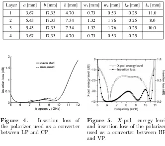
When two identical above-mentioned parts work together with the same meander line axial direction, a phase shift of nearly 180◦ is expected. Therefore, the polarizer can effect conversion between LHCP and RHCP, and can also cause arbitrary rotation of LP by rotating both parts simultaneously. As an example, an application of the polarizer to converting a wave from vertical polarization to horizontal is demonstrated. In this application, the angle φ is set as 45◦, and an air gap of 12 mm thick is inserted between the two parts. Fig. 5 shows the insertion loss and cross polarized (X-pol.) energy level of the polarizer for normal incidence. At the above-mentioned frequency band, i.e., from 5.6 GHz to 10.4 GHz, the insertion loss is less than 0.3 dB, as well as theX-pol. energy level less than−15 dB.
Table 1. Dimensions of the polarizer.
Layer a[mm] b[mm] h[mm] w1[mm] w2[mm] ldi[mm] l0i[mm]
1 3.67 17.33 4.70 0.73 0.53 0.25 11.0
2 5.43 17.33 7.34 1.32 1.76 0.25 8.0
3 5.43 17.33 7.34 1.32 1.76 0.25 10.0
4 3.67 17.33 4.70 0.73 0.53 0.25
5 6 7 8 9 10 11 12
0 0.5 1 1.5 2
frequency (GHz)
insertion loss (dB)
calculated measured
Figure 4. Insertion loss of the polarizer used as a converter between LP and CP.
5. CONCLUSION
A multifunctional polarizer is designed. The polarizer consists of two independent parts. when only one part is at work, the polarizer can effect conversion between LP and CP. When both parts work together, the polarizer can cause arbitrary rotation of linear polarization, and effect left-hand to right-hand circular polarization conversion.
REFERENCES
1. Young, L., L. A. Robinson, and C. A. Hacking, “Meander-line polarizer,” IEEE Trans. Antennas Propag., Vol. 21, 376–378, 1973.
2. Chu, R. S. and K. M. Lee, “Analytical model of multilayered meander-line polarizer plate with normal and oblique plane-wave incidence,” IEEE Trans. Antennas Propag., Vol. 35, 652–661, 1987.
3. Bhattacharyya, A. K. and T. J. Chwalek, “Analysis of multilay-ered meander line polarizer,” Int. J. Microwave Millimeter-wave CAE, Vol. 7, 442–454, 1997.
4. Burger, H. A. and A. Division, “A dual polarized antenna system using a meanderline polarizer,”IEEE Antennas Propag. Soc. Int. Symp. Dig., Vol. 16, 55–58, 1978.
5. Wu, T. K., “Meander-line polarizer for arbitrary rotation of linear polarization,”IEEE Microwave Guided Wave Lett., Vol. 4, No. 6, 199–201, 1994.
6. Awasthi, S. K., U. Malaviya, S. P. Ojha, N. K. Mishra, and B. Singh, “Design of a tunable polarizer using a one-dimensional nano sized photonic bandgap structure,”Progress In Electromagnetics Research B, Vol. 5, 133–152, 2008.