Conference Chair:Prof.Dr.G.ManojSomeswar, Director General, Global Research Academy, Hyderabad,
Design & Development of Error Minimizing Based Framework to
Obtain Better Jammer Location Estimation and Better
Performance
N.Ranga Reddy
1; A. Sravanthi
2& Prof.Dr.G. Manoj Someswar
31
M.Tech.(CSE) from Narasimha Reddy Engineering College, Affiliated to JNTUH, Hyderabad,
Telangana, India
2
M.Tech. (CSE), Assistant Professor, Department of CSE, Narasimha Reddy Engineering College,
Affiliated to JNTUH, Hyderabad, Telangana, India
3
B.Tech., M.S.(USA), M.C.A., Ph.D., Principal & Professor, Department Of CSE, Anwar-ul-uloom
College of Engineering & Technology, Affiliated to JNTUH, Vikarabad, Telangana, India
ABSTRACT:
Jammers can severely disrupt the communications in wireless networks, and jammers’ position information allows the defender to actively eliminate the jamming attacks. Thus, in this research paper, we aim to design a framework that can localize one or multiple jammers with a high accuracy. Most of existing jammer-localization schemes utilize indirect measurements (e.g., hearing ranges)affected by jamming attacks, which makes it difficult to localize jammers accurately. Instead, we exploit a direct measurement—the strength of jamming signals (JSS). Estimating JSS is challenging as jamming signals may be embedded in other signals. As such, we devise an estimation scheme based on ambient noise floor and validate it with real-world experiments. To further reduce estimation errors, we define an evaluation feedback metric to quantify the estimation errors and formulate jammer localization as a nonlinear optimization problem, whose global optimal solution is close to jammers’ true positions. We explore several heuristic search algorithms for approaching the global optimal solution, and our simulation results show that our error-minimizing-based framework achieves better performance than the existing schemes. In addition, our error-minimizing framework can utilize indirect measurements to obtain a better location estimation compared with prior work.
KEYWORDS: Wireless Sensor Networks (WSNs); Jamming Signals (JSS); Ambient Noise Floor (ANF);
Least-Squares (LSQ)
INTRODUCTION
Distributed computing is a field of computer science that studies distributed systems. A distributed system is a software system in which components located on networked computers communicate and coordinate their actions by passing messages. The components interact with each other in order to achieve a common goal. There are many alternatives for the message passing mechanism, including RPC-like connectors and message queues. Three significant characteristics of distributed systems are:
concurrency of components, lack of a global clock, and independent failure of components. An important goal and challenge of distributed systems is location transparency. Examples of distributed systems vary from SOA-based systems to massively multiplayer online games to peer-to-peer applications.
Conference Chair:Prof.Dr.G.ManojSomeswar, Director General, Global Research Academy, Hyderabad, Distributed computing also refers to the use of
distributed systems to solve computational problems. In distributed computing, a problem is divided into many tasks, each of which is solved by one or more computers, which communicate with each other by message passing.[1]
The word distributed in terms such as "distributed system", "distributed programming", and "distributed algorithm" originally referred to computer networks where individual computers were physically distributed within some geographical area. The terms are nowadays used in a much wider sense, even referring to autonomous processes that run on the same physical computer and interact with each other by message passing. While there is no single definition of a distributed system, the following defining properties are commonly used:
There are several autonomous computational entities, each of which has its own local memory.
The entities communicate with each other by message passing.
In this article, the computational entities are called computers or nodes.
A distributed system may have a common goal, such as solving a large computational problem.] Alternatively, each computer may have its own user with individual needs, and the purpose of the distributed system is to coordinate the use of shared resources or provide communication services to the users.[2]
Other typical properties of distributed systems include the following:
The system has to tolerate failures in individual computers.
The structure of the system (network topology, network latency, number of computers) is not known in advance, the system may consist of different kinds of computers and network links, and the
system may change during the execution of a distributed program.
Each computer has only a limited, incomplete view of the system. Each computer may know only one part of the input.
Distributed systems are groups of networked computers, which have the same goal for their work. The terms "concurrent computing", "parallel computing", and "distributed computing" have a lot of overlap, and no clear distinction exists between them. The same system may be characterized both as "parallel" and "distributed"; the processors in a typical distributed system run concurrently in parallel. Parallel computing may be seen as a particular tightly coupled form of distributed computing, and distributed computing may be seen as a loosely coupled form of parallel computing[3]. Nevertheless, it is possible to roughly classify concurrent systems as "parallel" or "distributed" using the following criteria:
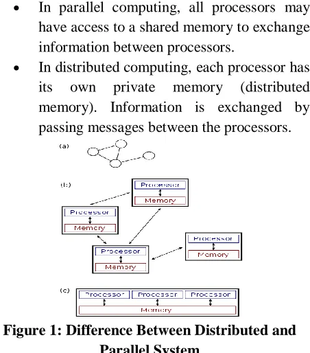
In parallel computing, all processors may have access to a shared memory to exchange information between processors.
In distributed computing, each processor has its own private memory (distributed memory). Information is exchanged by passing messages between the processors.
Figure 1: Difference Between Distributed and Parallel System
Conference Chair:Prof.Dr.G.ManojSomeswar, Director General, Global Research Academy, Hyderabad, as usual, the system is represented as a network
topology in which each node is a computer and each line connecting the nodes is a communication link. Figure (b) shows the same distributed system in more detail: each computer has its own local memory, and information can be exchanged only by passing messages from one node to another by using the available communication links. Figure (c) shows a parallel system in which each processor has a direct access to a shared memory.[4]
The situation is further complicated by the traditional uses of the terms parallel and distributed algorithm that do not quite match the above definitions of parallel and distributed systems; see the section Theoretical foundations below for more detailed discussion. Nevertheless, as a rule of thumb, high-performance parallel computation in a shared-memory multiprocessor uses parallel algorithms while the coordination of a large-scale distributed system uses distributed algorithms.[5]
LITERATURE SURVEY
Jamming attacks are especially harmful when ensuring the dependability of wireless communication. Finding the position of a jammer will enable the network to actively exploit a wide range of defense strategies. In this paper, we focus on developing mechanisms to localize a jammer by exploiting neighbor changes. We first conduct jamming effect analysis to examine how the communication range alters with the jammer's location and transmission power using free-space model.[6] Then, we show that a node's affected communication range can be estimated purely by examining its neighbor changes caused by jamming attacks and thus, we can perform the jammer location estimation by solving a least-squares (LSQ) problem that exploits the changes of communication range. Compared with our previous iterative-search-based virtual force algorithm, our LSQ-iterative-search-based algorithm exhibits lower computational cost (i.e., one step instead of iterative searches) and higher localization accuracy. Furthermore, we analyze the
localization challenges in real systems by building the log-normal shadowing model empirically and devising an adaptive LSQ-based algorithm to address those challenges. The extensive evaluation shows that the adaptive LSQ-based algorithm can effectively estimate the location of the jammer even in a highly complex propagation environment.[7] Jamming attacks and unintentional radio interference are one of the most urgent threats harming the dependability of wireless communication and endangering the successful deployment of pervasive applications built on top of wireless networks. Unlike the traditional approaches focusing on developing jamming defense techniques without considering the location of jammers, we take a different viewpoint that the jammers' position should be identified and exploited for building a wide range of defense strategies to alleviate jamming.[8] In this paper, we address the problem of localizing multiple jamming attackers coexisting in wireless networks by leveraging the network topology changes caused by jamming. We systematically analyze the jamming effects and develop a framework that can partition network topology into clusters and can successfully estimate the positions of multiple jammers even when their jamming areas are overlapping. Our experiments on a multi-hop network setup using MicaZ sensor nodes validate the feasibility of real-time collection of network topology changes under jamming and our extensive simulation results demonstrate that our approach is highly effective in localizing multiple attackers with or without the prior knowledge of the order that the jammers are turned on.[9]
Conference Chair:Prof.Dr.G.ManojSomeswar, Director General, Global Research Academy, Hyderabad, collaborative jamming attacks. We develop an
x-rayed jammed-area localization (X-ray) algorithm which skeletonizes jammed areas and estimates the jammer locations based on bifurcation points on skeletons of jammed areas. Our extensive simulation results demonstrate that with one run of the algorithms, X-ray is efficient in localizing multiple jammers in WSN with small errors.[10]
Preventing denial-of-service attacks in wireless sensor networks is difficult primarily because of the limited resources available to network nodes and the ease with which attacks are perpetrated. Rather than jeopardize design requirements which call for simple, inexpensive, mass-producible devices, we propose a coping strategy that detects and maps jammed regions.[11] We describe a mapping protocol for nodes that surround a jammer which allows network applications to reason about the region as an entity, rather than as a collection of broken links and congested nodes. This solution is enabled by a set of design principles: loose group semantics, eager eavesdropping, supremacy of local information, robustness to packet loss and failure, and early use of results.[12] Performance results show that regions can be mapped in 1-5 seconds, fast enough for real-time response. With a moderately connected network, the protocol is robust to failure rates as high as 25 percent.[13]
The proliferation of mobile computing devices and local-area wireless networks has fostered a growing interest in location-aware systems and services. In this paper we present RADAR, a radio-frequency (RF)-based system for locating and tracking users inside buildings. RADAR[14] operates by recording and processing signal strength information at multiple base stations positioned to provide overlapping coverage in the area of interest. It combines empirical measurements with signal propagation modeling to determine user location and thereby enable location-aware services and applications. We present experimental results that
demonstrate the ability of RADAR to estimate user location with a high degree of accuracy[15]
SYSTEM STUDY FEASIBILITY STUDY
The feasibility of the project is analyzed in this phase and business proposal is put forth with a very general plan for the project and some cost estimates. During system analysis the feasibility study of the proposed system is to be carried out. This is to ensure that the proposed system is not a burden to the company. For feasibility analysis, some understanding of the major requirements for the system is essential.
Three key considerations involved in the feasibility analysis are
ECONOMICAL FEASIBILITY TECHNICAL FEASIBILITY SOCIAL FEASIBILITY
ECONOMICAL FEASIBILITY
This study is carried out to check the economic impact that the system will have on the organization. The amount of fund that the company can pour into the research and development of the system is limited. The expenditures must be justified. Thus the developed system as well within the budget and this was achieved because most of the technologies used are freely available. Only the customized products had to be purchased.
TECHNICAL FEASIBILITY
This study is carried out to check the technical feasibility, that is, the technical requirements of the system. Any system developed must not have a high demand on the available technical resources. This will lead to high demands on the available technical resources. This will lead to high demands being placed on the client. The developed system must have a modest requirement, as only minimal or null changes are required for implementing this system.
SOCIAL FEASIBILITY
Conference Chair:Prof.Dr.G.ManojSomeswar, Director General, Global Research Academy, Hyderabad, the process of training the user to use the system
efficiently. The user must not feel threatened by the system, instead must accept it as a necessity. The level of acceptance by the users solely depends on the methods that are employed to educate the user about the system and to make him familiar with it. His level of confidence must be raised so that he is also able to make some constructive criticism, which is welcomed, as he is the final user of the system.
SYSTEM DESIGN SYSTEM ARCHITECTURE:
Figure 2 : System Architecture DATA FLOW DIAGRAM:
1. The DFD is also called as bubble chart. It is a simple graphical formalism that can be used to represent a system in terms of input data to the system, various processing carried out on this data, and the output data is generated by this system.
2. The data flow diagram (DFD) is one of the most important modeling tools. It is used to model the system components. These components are the system process, the data used by the process, an external entity that interacts with the system and the information flows in the system.
3. DFD shows how the information moves through the system and how it is modified by a series of transformations. It is a graphical technique that depicts information flow and the transformations that are applied as data moves from input to output.
4. DFD is also known as bubble chart. A DFD may be used to represent a system at any level of abstraction. DFD may be partitioned into levels that represent increasing information flow and functional detail.
UML DIAGRAMS
UML stands for Unified Modeling Language. UML is a standardized general-purpose modeling language in the field of object-oriented software engineering. The standard is managed, and was created by, the Object Management Group.
The goal is for UML to become a common language for creating models of object oriented computer software. In its current form UML is comprised of two major components: a Meta-model and a notation. In the future, some form of method or process may also be added to; or associated with, UML.
The Unified Modeling Language is a standard language for specifying, Visualization, Constructing and documenting the artifacts of software system, as well as for business modeling and other non-software systems.
The UML represents a collection of best engineering practices that have proven successful in the modeling of large and complex systems.
The UML is a very important part of developing objects oriented software and the software development process. The UML uses mostly graphical notations to express the design of software projects.
GOALS:
The Primary goals in the design of the UML are as follows:
1. Provide users a ready-to-use, expressive visual modeling Language so that they can develop and exchange meaningful models. 2. Provide extendibility and specialization
mechanisms to extend the core concepts. 3. Be independent of particular programming
Conference Chair:Prof.Dr.G.ManojSomeswar, Director General, Global Research Academy, Hyderabad, 4. Provide a formal basis for understanding the
modeling language.
5. Encourage the growth of OO tools market. 6. Support higher level development concepts
such as collaborations, frameworks, patterns and components.
7. Integrate best practices.
USE CASE DIAGRAM:
A use case diagram in the Unified Modeling Language (UML) is a type of behavioral diagram defined by and created from a Use-case analysis. Its purpose is to present a graphical overview of the functionality provided by a system in terms of actors, their goals (represented as use cases), and any dependencies between those use cases. The main purpose of a use case diagram is to show what system functions are performed for which actor. Roles of the actors in the system can be depicted.
Server
Router
Client
FileTransfer
Locate Jammer
Find Jammed Nodes, Boundary Nodes, UnAffected Nodes
IP Address
Select Recieving Path
Recieve File
Figure 3 : Use Case Diagram CLASS DIAGRAM:
In software engineering, a class diagram in the Unified Modeling Language (UML) is a type of static structure diagram that describes the structure of a system by showing the system's classes, their attributes, operations (or methods), and the relationships among the classes. It explains which class contains information.
Figure 4 : Class Diagram SEQUENCE DIAGRAM:
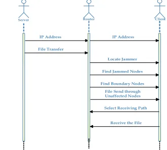
A sequence diagram in Unified Modeling Language (UML) is a kind of interaction diagram that shows how processes operate with one another and in what order. It is a construct of a Message Sequence Chart. Sequence diagrams are sometimes called event diagrams, event scenarios, and timing diagrams.
Server Client
IP Address
Router
Receive the File IP Address
File Transfer
Locate Jammer
Find Jammed Nodes
Find Boundary Nodes File Send through Unaffected Nodes
Select Receiving Path
Figure 5 : Sequence Diagram
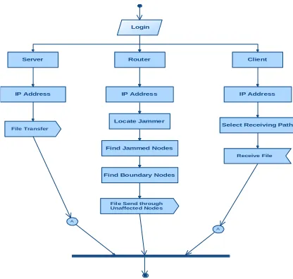
ACTIVITY DIAGRAM:
Conference Chair:Prof.Dr.G.ManojSomeswar, Director General, Global Research Academy, Hyderabad,
A
A Login
IP Address IP Address
Router Client
Server
Find Jammed Nodes Locate Jammer
IP Address
Select Receiving Path File Transfer
Find Boundary Nodes
File Send through Unaffected Nodes
Receive File
Figure 6 : Activity Diagram INPUT DESIGN
The input design is the link between the information system and the user. It comprises the developing specification and procedures for data preparation and those steps are necessary to put transaction data in to a usable form for processing can be achieved by inspecting the computer to read data from a written or printed document or it can occur by having people keying the data directly into the system. The design of input focuses on controlling the amount of input required, controlling the errors, avoiding delay, avoiding extra steps and keeping the process simple. The input is designed in such a way so that it provides security and ease of use with retaining the privacy. Input Design considered the following things:
What data should be given as input? How the data should be arranged or
coded?
The dialog to guide the operating personnel in providing input.
Methods for preparing input validations and steps to follow when error occur.
OBJECTIVES
1.Input Design is the process of converting a user-oriented description of the input into a computer-based system. This design is important to avoid
errors in the data input process and show the correct direction to the management for getting correct information from the computerized system.
2.It is achieved by creating user-friendly screens for the data entry to handle large volume of data. The goal of designing input is to make data entry easier and to be free from errors. The data entry screen is designed in such a way that all the data manipulates can be performed. It also provides record viewing facilities.
3.When the data is entered it will check for its validity. Data can be entered with the help of screens. Appropriate messages are provided as when needed so that the user will not be in maize of instant. Thus the objective of input design is to create an input layout that is easy to follow.
OUTPUT DESIGN
A quality output is one, which meets the requirements of the end user and presents the information clearly. In any system results of processing are communicated to the users and to other system through outputs. In output design it is determined how the information is to be displaced for immediate need and also the hard copy output. It is the most important and direct source information to the user. Efficient and intelligent output design improves the system’s relationship to help user decision-making.
1. Designing computer output should proceed in an organized, well thought out manner; the right output must be developed while ensuring that each output element is designed so that people will find the system can use easily and effectively. When analysis design computer output, they should Identify the specific output that is needed to meet the requirements.
2.Select methods for presenting information.
Conference Chair:Prof.Dr.G.ManojSomeswar, Director General, Global Research Academy, Hyderabad, The output form of an information system should
accomplish one or more of the following objectives. Convey information about past activities,
current status or projections of the Future.
Signal important events, opportunities, problems, or warnings.
Trigger an action. Confirm an action.
SYSTEM ANALYSIS EXISTING SYSTEM:
Jammer-localization schemes utilize indirect measurements (e.g., hearing ranges) affected by jamming attacks, which makes it difficult to localize jammers accurately. The emergence of software-defined radios has enabled adversaries to build intentional jammers to disrupt network communication with little effort. Unintentional interference or malicious jamming, one or multiplejammers/interferers may coexist and have a detrimental impact on network performance—both can be referred as jamming. To ensure the successful deployment of pervasive wireless networks, it is crucial to localize jammers, since the locations of jammers allow a better physical arrangement ofwireless devices that cause unintentional radio interference, or enable a wide range of defence strategies for combating malicious jamming attackers.
DISADVANTAGES OF EXISTING SYSTEM:
Indirect measurements (e.g., hearing ranges) affected by jamming attacks.
Difficult to localize jammers.
Disruption of network communication.
PROPOSED SYSTEM:
In proposed system, we focus on localizing one or multiple stationary jammers. Our goal is to extensively improve the accuracy of jammer localization. Current jammer-localization approaches mostly rely on parameters derived from the affected network topology, such as packet
delivery ratios, neighbour lists, and nodes’ hearing ranges. The use of these indirect measurementsderived from jamming effects makes it difficult to accurately localize jammers’ positions. Furthermore, they mainly localize one jammer and cannot cope with the cases that multiple jammers are located close to each other and their jamming effects overlap.
ADVANTAGES OF PROPOSED SYSTEM:
JSS utilizing the measurement of the ambient noise floor (ANF), which is readily availablefrom many commodity devices (e.g., MicaZ motes).
Avoid disturbance of network communication
Accuracy of the estimated locations.
SYSTEM TESTING
The purpose of testing is to discover errors. Testing is the process of trying to discover every conceivable fault or weakness in a work product. It provides a way to check the functionality of components, sub assemblies, assemblies and/or a finished product It is the process of exercising software with the intent of ensuring that the
Software system meets its requirements and user expectations and does not fail in an unacceptable manner. There are various types of test. Each test type addresses a specific testing requirement.
TYPES OF TESTS Unit testing
Conference Chair:Prof.Dr.G.ManojSomeswar, Director General, Global Research Academy, Hyderabad, ensure that each unique path of a business process
performs accurately to the documented specifications and contains clearly defined inputs and expected results.
Integration testing
Integration tests are designed to test integrated software components to determine if they actually run as one program. Testing is event driven and is more concerned with the basic outcome of screens or fields. Integration tests demonstrate that although the components were individually satisfaction, as shown by successfully unit testing, the combination of components is correct and consistent. Integration testing is specifically aimed at exposing the problems that arise from the combination of components.
Functional test
Functional tests provide systematic demonstrations that functions tested are available as specified by the business and technical requirements, system documentation, and user manuals.
Functional testing is centered on the following items:
Valid Input : identified classes of valid input must be accepted.
Invalid Input : identified classes of invalid input must be rejected.
Functions : identified functions must be exercised.
Output : identified classes of application outputs must be exercised.
Systems/Procedures: interfacing systems or procedures must be invoked.
Organization and preparation of functional tests is focused on requirements, key functions, or special test cases. In addition, systematic coverage pertaining to identify Business process flows; data fields, predefined processes, and successive processes must be considered for testing. Before functional testing is complete, additional tests are identified and the effective value of current tests is determined.
System Test
System testing ensures that the entire integrated software system meets requirements. It tests a configuration to ensure known and predictable results. An example of system testing is the configuration oriented system integration test. System testing is based on process descriptions and flows, emphasizing pre-driven process links and integration points.
White Box Testing
White Box Testing is a testing in which in which the software tester has knowledge of the inner workings, structure and language of the software, or at least its purpose. It is purpose. It is used to test areas that cannot be reached from a black box level.
Black Box Testing
Black Box Testing is testing the software without any knowledge of the inner workings, structure or language of the module being tested. Black box tests, as most other kinds of tests, must be written from a definitive source document, such as specification or requirements document, such as specification or requirements document. It is a testing in which the software under test is treated, as a black box .you cannot ―see‖ into it. The test provides inputs and responds to outputs without considering how the software works.
Unit Testing:
Unit testing is usually conducted as part of a combined code and unit test phase of the software lifecycle, although it is not uncommon for coding and unit testing to be conducted as two distinct phases.
Test strategy and approach
Field testing will be performed manually and functional tests will be written in detail.
Test objectives
All field entries must work properly.
Pages must be activated from the identified link.
Conference Chair:Prof.Dr.G.ManojSomeswar, Director General, Global Research Academy, Hyderabad,
Features to be tested
Verify that the entries are of the correct format
No duplicate entries should be allowed All links should take the user to the correct
page.
Integration Testing
Software integration testing is the incremental integration testing of two or more integrated software components on a single platform to produce failures caused by interface defects.
The task of the integration test is to check that components or software applications, e.g. components in a software system or – one step up – software applications at the company level – interact without error.
Test Results: All the test cases mentioned above
passed successfully. No defects encountered.
Acceptance Testing
User Acceptance Testing is a critical phase of any project and requires significant participation by the end user. It also ensures that the system meets the functional requirements.
Test Results: All the test cases mentioned above
passed successfully. No defects encountered.
IMPLEMENTATION MODULES:
Server Client
Jammer or Router Attack Analysis
MODULES DESCRIPTION: Server
In this module, we formulate the jammer localization problem under an error minimizing framework, aiming to achieve high localization accuracy. Our work localizes a jammer by utilizing the strength of jamming signals directly y through measuring the readily available ambient noise floor using commodity wireless devices.
Client
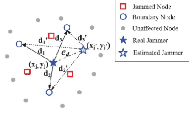
We first discuss which nodes can participate in jammer localization. . The network nodes can be classified into three categories according to the impact of jamming: unaffected node, jammed node, and boundary node:
Unaffected node: A node is unaffected if it can
receive packets from all of its neighbors after jamming is present. This type of node is barely affected by jamming and may not yield accurate JSS measurements.
Jammed node: A node is jammed if it
cannot receive messages from any of the unaffected nodes. We note that this type of node can measure JSS, but cannot report their measurements.
Jammed node: A node is jammed if it
cannot receive messages from any of the unaffected nodes. We note that this type of node can measure JSS, but cannot report their measurements.
Jammer or Router
The idea of incorporating features from gradient optimization into network operations has been used in the past for routing. In particular, Faruque et al. propose the use of a gradient based algorithm for the efficient forwarding of queries in sensor networks. Poor presents an on demand routing protocol for ad hoc networks, which uses a gradient descent logic in order to forward the packets based on the cost to destination. In particular, the source broadcasts the message along with the cost, and only the nodes that have a smaller cost relay the packet. In a similar fashion, Ruhil et al. forward the message to the neighbor node that is closer to the direction of the destination.
Attack Analysis
Conference Chair:Prof.Dr.G.ManojSomeswar, Director General, Global Research Academy, Hyderabad, The fuzzy logic-based localization scheme is
implemented in a simulator and compared to state-of-the-art solutions.
RESULTS &CONCLUSION
In this work, we addressed the problem of localizing jammers in wireless networks, aiming to extensively reduce estimation errors. The jammers could be several wireless devices causing unintentional radio interference or malicious colluding jamming devices who coexist and disturb the network together. Most of the existing schemes for localizing jammers rely on the indirect measurements of network parameters affected by jammers, for example, nodes’ hearing ranges, which makes it difficult to accurately localize jammers. In this work, we localized jammers by exploiting directly the JSS. Estimating JSS is considered challenging because they are usually embedded with other signals. Our estimation scheme smartly derives ANFs as the JSS utilizing the available signal strength measuring capability in wireless devices. The scheme samples signal strength regardless of whether the channel is busy or idle and estimates the ANF by filtering out regular transmission (if any) to obtain the JSS. We implemented an estimation scheme on MicaZ motes. Our experiment involving three jammers show that our estimation scheme can accurately derive the JSS from the measurements of ANF under various traffic scenarios.
To further improve the estimation accuracy, we designed an error-minimizing-based framework to localize jammers. In particular, we defined an evaluation feedback metric that quantifies the estimation errors of jammers’ positions. We studied the relationship between the evaluation feedback metric and estimation errors, and showed that the locations that minimize the feedback metric approaches jammers’ true locations and greedy algorithms may not find the global optimal solutions. Thus, we treated the evaluation feedback metric as the objective function for the error-minimizing purpose. We examined several heuristic
search algorithms (GA, GPS, and SA) under various network conditions: node densities, jammer’s transmission power, the propagation irregularity, and number of jammers. Besides, we examined our error-minimizing framework utilizing an indirect measurement—a hearing range. Our extensive simulation results show that our error minimizing- based search algorithms utilizing both the direct and indirect measurements outperform the existing algorithms in all experiment configurations. In particular, among the three searching algorithms, we found that GPS can find the best estimation of multiple jammers’ positions in the shortest duration.
REFERENCES
[1] K. Pelechrinis, I. Koutsopoulos, I. Broustis, and S.V. Krishnamurthy, ―Lightweight Jammer Localization in Wireless Networks: System Design and Implementation,‖ Proc. IEEE GLOBECOM, 2009.
[2] H. Liu, Z. Liu, Y. Chen, and W. Xu, ―Determining the Position of a Jammer Using a Virtual-Force Iterative Approach,‖ Wireless Networks, vol. 17, pp. 531-547, 2010.
[3] Z. Liu, H. Liu, W. Xu, and Y. Chen, ―Exploiting Jamming-Caused Neighbor Changes for Jammer Localization,‖ IEEE Trans. Parallel and Distributed Systems, vol. 23, no. 3, pp. 547-555, Mar. 2012.
[4] H. Liu, Z. Liu, Y. Chen, and W. Xu, ―Localizing Multiple Jamming Attackers in Wireless Networks,‖ Proc. 31st Int’l Conf. Distributed Computing Systems (ICDCS), 2011.
Conference Chair:Prof.Dr.G.ManojSomeswar, Director General, Global Research Academy, Hyderabad, [6] A. Wood, J. Stankovic, and S. Son, ―JAM: A
Jammed-Area Mapping Service for Sensor Networks,‖ Proc. 24th IEEE Int’l Real-Time Systems Symp., 2003.
[7] W. Xu, W. Trappe, Y. Zhang, and T. Wood, ―The Feasibility of Launching and Detecting Jamming Attacks in Wireless Networks,‖ Proc. ACM MobiHoc, 2005.
[8] A. Goldsmith, Wireless Communications. Cambridge Univ. Press, 2005.
[9] T. Rappaport, Wireless Communications— Principles and Practice. Prentice-Hall, 2001.
[10] P. Bahl and V.N. Padmanabhan, ―RADAR: An In-Building RFBased User Location and Tracking System,‖ Proc. IEEE INFOCOM, 2000.
[11] J. Yang, Y. Chen, and J. Cheng, ―Improving Localization Accuracy of RSS-Based Lateration Methods in Indoor Environments,‖ Ad Hoc and Sensor Wireless Networks, vol. 11, nos. 3/4, pp. 307-329, 2011.
[12] D. Goldberg, Genetic Algorithms in Search, Optimization and Machine Learning. Addison-Wesley, 1989.
[13] E. Polak, Computational Methods in Optimization: A Unified Approach. Academic Press, 1971.
[14] P.V. Laarhoven and E. Aarts, Simulated Annealing: Theory and Applications. Springer, 1987.