LTE Physical Layer Analysis with
Conventional and RCIC Turbo Codes
Anju Mariam Abraham
1, Binu Mathew
2PG Student, Dept. of ECE, Amal Jyothi College of Engineering, Kanjirapally, Kerala, India1
Assistant Professor, Dept. of ECE, Amal Jyothi College of Engineering,Kanjirapally, Kerala, India2
ABSTRACT: Long Term Evolution is the new standard specified for the wireless mobile communication by the 3rd Generation Partnership Project(3GPP).With the advancements in the field ofmobile communication the demand for better services also started growing. LTE with itsadvanced features like high spectral efficiency,better coverage and low latency meets therequirements of the users. It gained its advanced features with the introduction of thephysical layer(PHY). It is a new protocol specified by the LTE Radio Access Network(RAN).The PHY handles coding,modulation,mapping,demodulation and decoding processes. Inthis work, the downlink physical layer is analyzed in detail. Turbo coding along with ratematching forms the important part in the downlink shared channel processing. The LTEdownlink physical layer with its conventional turbo coding as the channel coding technique issimulated. Next, the turbo coding is replaced by its counterpart Rate Compatible InsertionConvolutional (RCIC) Turbo coding. The different PSD plots show that RCIC coded physicallayer gives a better performance compared to the conventional turbo coded system.
KEYWORDS: LTE, PHY, PDSCH, RCIC
I.INTRODUCTION
LTE is the acronym for Long Term Evolution. It is a new standard specified by the 3rdGeneration Partnership Project
(3GPP) for the modern wireless communication[1] and itis currently marketed as 4G LTE. It provides a major advancement in the field of cellulartechnology. LTE is continuously being developed so that future requirements are being metin the best possible way. It allows high peak data rates, improved system capacity andcoverage, multiple antenna support, low latency and reduced operating cost. The design ofLTE infrastructure is simple so that it is easy to deploy and operate, with flexible technologythat can be deployed in a wide variety of frequency bands. The performance of LTE is much better when compared to the previous technologies such as High speed Packet Access (HSPA) and Universal Mobile Telecommunications system (UMTS). It is achieved by the introduction of a physical layer and redefining the core network. The Physical Layer (PHY) of LTE is one of the protocol entities of LTE Radio Access Network (RAN). The PHY is responsible for transferring information to and from the MAC layer. It also performs the function of transfer of data between the base station and user equipments. It carries out various operations such as coding, decoding, modulation, demodulation, mapping etc.
encoding. These codes can be decoded using the same decoder used for mother codes. In [5] and [6], the rate compatible insertion convolutional (RCIC) codes are discussed. These codes achieved lower code rates by inserting dummy bits into the information sequence before turbo encoding. These codes were capable of giving better frame error rate as well as improved convergence speed.
III.LTE DOWNLINK PHYSICAL LAYER
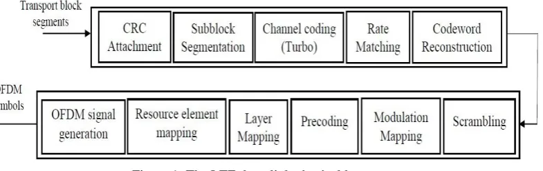
The physical layer was included in the LTE architecture so as to improve its performance compared to the previous technologies. Here, the downlink section of the physical layer is analysed in detail. The LTE downlink physical layer processing consists of two sections: downlink shared channel (DL-SCH) processing and physical downlink shared channel (PDSCH) processing. The LTE downlink transmitter section is shown in Figure 1. The various steps involved in the DL-SCH processing [2] are given below.
Transport Block CRC Attachment: The cyclic redundancy check (CRC) is performed for error checking. For each block CRC will be performed separately. A 24 bit CRC is performed. A cyclic generator polynomial, described as gCRC24Ais used for dividingthe transport block. Afterperforming the CRC, the parity bits are
appended at the end of the transport block.
Figure 1: The LTE downlink physical layer
Subblock Segmentation: When the size of the transport block is too large, then it is segmented into smaller blocks. The minimum block size is 40 bits and the maximum is 6144 bits. So, when the size of the block is larger than 6144 bits, it is segmented according to the equation, C = [B / (Z - L)] where Z= 6144, L=40 and B is the size of the transport block. If the size of transport block is smaller than 40 bits, then filler bits are appended along with the transport block.
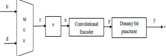
Figure 2: The turbo encoder
Rate Matching: The main function of the rate matching block is to give a single output stream that satisfies the desired code rate. The three output bit streams from the turbo encoder are interleaved. A circular buffer is created by performing bit collection. These bits are selected and then pruned from the buffer to create a single output bitstream.
Code Block Concatenation: The code blocks are serially concatenated together to form code words. The steps involved in PD-SCH processing [2] are:
Scrambling: The code words are multiplied by an orthogonal user specific scrambling sequence. This scrambling sequence is generated using a 31 length Gold code sequence. The main idea behind scrambling is to provide intercell interference rejection.
Modulation: Modulation can be performed by QPSK, 16QAM or 64QAM. This provides the flexibility for the scheme to transmit the information most effectively.
Layer Mapping: The complex symbols are mapped to one, two or four layers depending on the number of transmit antennas.
Precoding: In LTE, precoding is of three types: spatial multiplexing, transmit diversity and single antenna port transmission.
Resource Element Mapping: The complex symbols are mapped to the resource elements not occupied by the reference and synchronization signals. The number of resource elements mapped depends on the number of resource blocks allocate to the PDSCH.
OFDM Modulation: The symbols undergo OFDM modulation on different orthogonal subcarriers. It offers high spectral efficiency, robustness to multipath fading, interference rejection and MIMO transmission.
IV.LTE PHY WITH RCIC TURBO CODE
The RCIC encoder consists of a multiplexer, an interleaver, a convolutional encoder anda dummy bit puncturer. The information bits b and dummy bits dare multiplexed together to obtain a vector 𝑥 . The multiplexed stream undergoes interleaving.The interleaver assigns the dummy bits equidistantly within the information sequence. This is achieved by a dummybit insertion algorithm[6].
Dummy bit insertion
Initialize: xk = 0 for 1 ≤ k ≤ lx
for all m such that 1 ≤ m ≤ lb do
xk = bm with k= round ((m - 1). (lb+ld) / lb ) + 1
end for.
where, lb is the length of information bit sequence b and ld is the length of dummy bitsequence d.
The interleaved sequence x then undergo convolutional encoding to obtain a stream y. Itinvolves the use of shift registers and a logic that uses modulo two additions. If the encoded sequence is found to be non-systematic then the dummy bits are punctured using a dummybit puncturer. If it is found to be a systematic code, then no puncturing is employed.
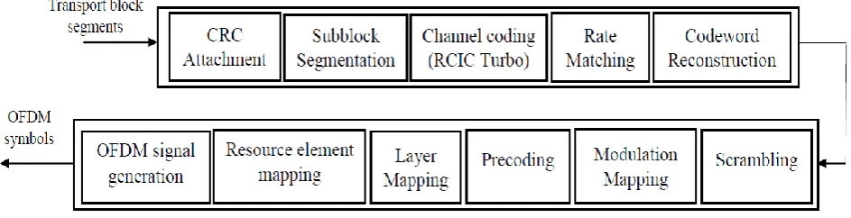
Figure 4: The LTE downlink PHY with RCIC turbo encoder
The LTE downlink physical layer with RCIC turbo encoder is shown in Figure 4. The turbo encoder is replaced with the RCIC turbo encoder. The remaining blocks are all the same as explained in section III.
V. RESULTS AND DISCUSSION
The LTE downlink physical layer with both turbo coding and RCIC turbo coding are simulated.Matlab is used as the simulation platform. The simulation progresses in the orderof blocks as explained in section III and IV. In the second case, i.e., LTE downlink physical layer with RCIC turbo coding, the difference comes in the channel coding part. Here, the conventionalturbo encoder is replaced by a new RCIC turbo encoder. An RCIC turbo encoder iscomposed of two RCIC encoders separated by an interleaver. In this work, power spectral density is used for analyzing the performance of both systems. Three types of PSDs are used.
1. PSD using Periodogram
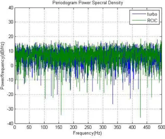
Figure 5: The Periodogram PSD
When the power spectra are computed for the entiresignal at once, it becomes a periodogram. The periodograms of segments of the time signalare averaged to form the power spectral density. The Periodogram PSD plots for turbo andRCIC coded systems are shown in Figure 5. The plot gives only a vague idea of the powerlevels of the two cases
.
2.PSD using Welch’s Method
Figure 6: The Welch PSD
The Welch PSD obtained for both the systems under study is shown in Figure 6.Even though the plot shows that RCIC coded signalshave a higher peak compared to turbo coded signals, it is difficult to distinguish between thetwo signals.
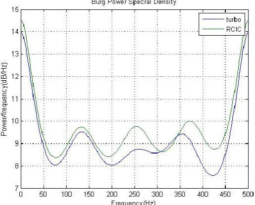
3. PSD using Burg Method
In this method, an autoregressive model is applied to the signal. It minimizes the forwardand backward prediction errors when the AR parameters are defined to satisfy Levinson-Durbin recursion. Hence, as a result it generates a harmonic mean of the partial correlation coefficients of the forward and backward linear prediction error.It produces estimates of very high resolution as it uses linear prediction to estimate the signal outside of its known data record. This in turn removes all the sidelobes present.
This method helps in resolving closely spaced sinusoids with low noise levels. It is also an efficientmethod for estimating short data records. It is computationally efficient also. The Burg PSDplots for turbo and RCIC is shown in Figure 7
.
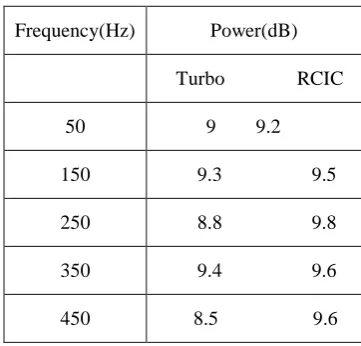
Table 1: The power across different frequency ranges for turbo and RCIC turbo coded signals
From Table 1, it can be observed that the RCIC coded LTE system signals have more power over the different frequency ranges when compared to the turbo coded system
VI.CONCLUSION
In this work, LTE physical layer is analyzed with conventional turbo coding and RCIC turbocoding as the channel coding scheme in downlink. The turbo coding which is a forward errorcorrection scheme is replaced by the RCIC turbo code which has better convergence speedand frame error rate. The power spectral density was used as the parameter for analysis. Three different PSDs were plotted. The periodogram PSD plot gives a vague differenceamong the turbo and RCIC coded signals. In the Welch PSD, the noise in the power spectrais considerably reduced. Still, clear distinction between the two signals is a difficult task.The third PSD method, the Burg PSD plot shows the two signals separately. The values of the signal power obtained at different ranges of frequencies show that the RCIC turbo coded
LTE physical layer achieved a better performance than the conventional turbo coded LTEphysical layer in terms of the signal power.
REFERENCES
[1] Temitope O Takpor and Francis E. Idachaba, “Analysis and Simulation of LTE Downlink and Uplink Transceiver”, Proceedings of the World
Congress on Engineering2014 Vol I, July 2 - 4, 2014, London, U.K.
[2] Houman Zarinkoub, “Understanding LTE with Matlab”, Wiley Publications, 2014.
[3] O. M. Collins and M. Hizlan, “Determinate State Convolutional Codes”, IEEE Trans. Commun., vol. 41, no. 12, pp. 1785–1794, 1993.
[4] W. Xu and J. Romme, “A Class of Multirate Convolutional Codes by Dummy Bit Insertion”, in Proc. 2000 IEEE Global Telecommun. Conf.
[5] Tobias Breddermann and Peter Vary, “Rate-Compatible Insertion Convolutional Turbo Codes: Analysis and Application to LTE”, IEEE Transactions on Wireless Communications 2014.
[6] T. Breddermann, “On Rate-Compatible Insertion Convolutional Turbo Codes and HARQ for Mobile Communications”, Ph.D. dissertation, RWTH Aachen University, 2013.
Frequency(Hz) Power(dB)
Turbo RCIC
50 9 9.2
150 9.3 9.5
250 8.8 9.8
350 9.4 9.6