ISSN 2286-4822 www.euacademic.org
Impact Factor: 3.4546 (UIF) DRJI Value: 5.9 (B+)
Beamforming in Massive MIMO
MOHAMMED FAROOQ University of Sudan of Science and Technology Electronic and Communication Engineering Department Sudan Prof. RASHID ABDELHALEEM SAEED University of Sudan of Science and Technology Electronic and communication Engineering Department Sudan ABDULLAH THAIER ABDALSATIR
University of Diyala, Iraq
Abstract:
Beamforming is a type of spatial filtering and a process of signal processing techniques that is used in sensor arrays or antenna array for directing the signal transmission or reception. This is achieved by combining elements that in a phased array in such as a way that signals at specific angles face constructive interference while others facing destructive interference. Beamforming is used at both the transmitting end and receiving end in order to realize spatial selectivity.
Key words: LMS;RLS;Massive MIMO; Beamforming
1. PREFACE
The Diversity Coding is a type of spatial coding techniques for used for MASSIVE MIMO system in wireless channels. Usually wireless channels severely affected from many factors such as fading that causes unreliability in data decoding. Fundamentally, in diversity coding multiple copies of codes is send through multiple transmitter antennas, so as to improve the QoS of the data in the reception. If one of channels fails to deliver, the others channel used for data decoding. Beamforming is required achieves spatial diversity and spatial multiplexing for Massive MIMO. Beamforming is used in radio signals or sound waves. It has found a various applications in many radar systems, sonar systems, wireless communications, radio astronomy, acoustics and biomedicine. an adaptive bamforming is used to detect/ estimate a spacific signal at the output of a sensor-array by means of optimal spatial filtering and interference rejection.
The beamforming algorithms applied at digital baseband can get very complex procedure, if all beamforming is done at baseband, each antenna requires a unique radio frequency feed. With the high frequencies while using large number of antenna elements, it causes a very costly and increase loss also increase the complexity in the system. in order to solve these issues, a hybrid beamforming was used analog components and not digital components.
There are many different functionality that can be performed based on analog components compared with the digital baseband.
advantages of multiple Antenna at the receiver, such as gain and spatial diversity.
The advantages of MASSIVE MIMO communication, which distribute the physical channel between many transmiters and receivers antenna.
The MASSIVE MIMO systems provide many advantages compared to single-antenna-to-single-antenna communication such as the sensitivity to fading is reduced by using spatial diversity that is provided by multiple-channels or pathes under varity of environmental conditions, the power that is required for a high spectral-efficiency communication can be theoratically reduced by avoiding the compressive region of the information-theoretic capacity bound. and the spectral efficiency can be defined as the total number of in formation bits/second / Hertz transmitted from one array to the other array.
2. PROBLEM DEFINITION:
The increase demand on system capacity, requires the usage of array antenna with a dedicated quality of service parameters (QoS), thus the development of the multi antenna transmission and receiving require a beam forming in order to focus on the target. The main problem is non beamforming in MASSIVE MIMO can results a decreasing quality of service parameter order.
3. OBJECTIVE:
A- Study and analysis to multiple in multiple out MMO system of Antenna.
B- Study and analysis MASSIVE MIMO of beamforming techniques.
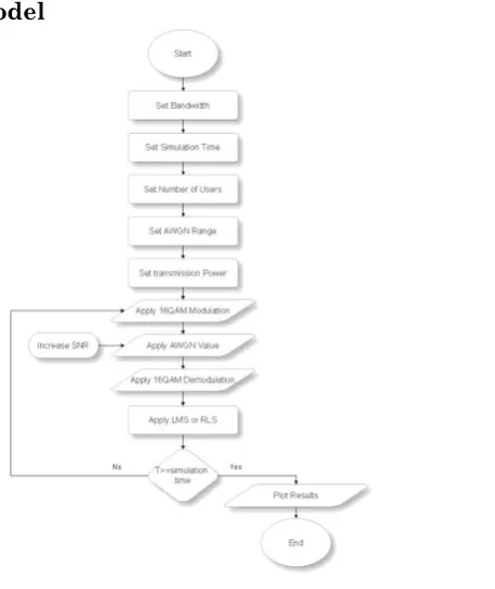
4. METHODOLOGY:
A- Descriptive analysis. B- Mathematical model. C- Implement codes.
D- Design of computer model. E- Implement Matlab simulation.
5- PROJECT SCENARIO
In order to get results from the simulation some parameters should be figured out as assumption based on related works such as the reference bandwidth and the power on the transmitter site and the optimal value of the noise value. In this results ten users was configured into the simulation in order to evaluate the performance of beamforming, each user has a distance and different parameters, thus a randomized function was used to generate random values.
The following table represents the parameters used in the simulation.
Table.1: simulation parameters
No. Parameter Value
1 Simulation time 20 seconds
2 bandwidth 20 MHz
3 No. of Users 10 users 4 Attenuation 1.4553e+03
6 Transmission power 1.029671474965957e+02 7 Power Ratio 0.332675171227804
6- Mathematical Confederations and Equations
1- LMS Algorithm
In to c the LMS algorithm there are some initial calculations is required. Such as the received signal at the nth element can be given as:
The least mean squares algorithm is a gradient based optimization technique. The reference signal used to update the weights at each iteration is given by
W (n+1) =w (n) + μx (n) e*(n)
The constant μ is called the step size. It determines how close the weights are moving to optimum value. The convergence of the algorithm depends on the step size. Typical values for the step size are 0 < μ < λmax.
2- NLMS Algorithm
The normalized LMS algorithm was modified form of the standard LMS algorithm. It uses a time varying adaptive step size μ (n).
RLS Algorithm
Computer Model
Accumulated Throughput Comparison
Figure 4.2 illustrates the accumulated throughput before and after RLSs the X axis represent the simulation time in ms and the Y axis represents Accumulated Throughput in Kbit/sec. The accumulated throughput has been improved by 47%. and this improvement was occurred due to the amplification of the RLS to the signal and the ability to establish new communication channel that increases the throughput of the system.
Figure (3) Accumulated throughput LMS vs. RLSs
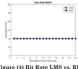
Bit Rate Comparison
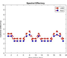
Spectral Efficiency
Figure 4.4 shows the compression of the spectral efficiency before and after RLSs the X axis represent the simulation time in ms and the Y axis represents the Spectral Efficiency in db. It’s very clear that the spectral efficiency has been improved by 40% The value of spectral efficiency depends on amount of bite rate and the bandwidth. When the bit rate increases the spectral will increase too.
Figure (5) Spectral Efficiency LMS vs. RLSs
Transmission Delay Comparison
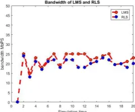
Bandwidth Comparison
Figure 4.6 represent the bandwidth before and after adding RLSs the X axis represent the simulation time in ms and the Y axis represents the Bandwidth in MHz show the variation of Bandwidth in LMS and RLS. It’s clear that the value of Bandwidth increased in RLS case applied by 11.3 % and this improvement was occurred due to the new communication channel that is provided by the RLS increases the bandwidth of the system.
Figure (7) Bandwidth LMS vs. RLSs
7-CONCLUSION
In this project a focus on the increase demand on system capacity, that requires the usage of array antenna with a dedicated quality of service parameters (QoS), based on beamforming in order to focus on the target. With a main problem is non beamforming in MASSIVE MIMO can results a decreasing quality of service parameter.
The aim of the project focus on the study and analysis to multiple in multiple out MMO system of Antenna, study and analysis MASSIVE MIMO of beamforming techniques and Study and analysis the mathematical model.
A compare the performance of Adaptive beam forming algorithms LMS & RLS for smart antenna. First we will implement three different geometries: Linear, Circular & Planer, in next stage we will implement the different algorithms for updating the weights of smart antenna system. Circular geometry not used for practical applications. Planar array geometry gives good array factor compare to other geometries. LMS algorithm used for fixed step size.
REFERENCES
[1] Advanced 3G and 4G wireless communication systems video lecture series by Prof. Adithya k. Jagannatham. [Online]. Available: http://www.nptel.iitk.ac.in
[2] Andrea Goldsmith, wireless communications, Stanford university,
[3] Md. Mejbaul Haque, Mohammad Shaifur Rahman and Ki-Doo Kim, Performance Analysis of MASSIVE MIMO-OFDM for 4G wireless systems under Rayleigh Fading channel, International Journal of Multimedia and Ubiquitous Engineering vol. 8, No. 1, Jan 2013.
[4] Prof. Monica Khanore, Ms. Quanitah shaikh, An overview of MASSIVE MIMO-OFDM system, International Journal of Engineering Research and Applications (IJERA) ISSN : 2248-9622 National Conference on Emerging Trends in Engineering & Technology (VNCET-30 Mar’12)
[5] http://www.flarion.com/OFDM for Mobile data communication