Available Online atwww.ijcsmc.com
International Journal of Computer Science and Mobile Computing
A Monthly Journal of Computer Science and Information Technology
ISSN 2320–088X
IJCSMC, Vol. 4, Issue. 8, August 2015, pg.61 – 65
RESEARCH ARTICLE
Comparison of DFT and Wavelet based Image
Modification Techniques
Vikash, Rajesh Parihar
(Guide)Abstract- This research is a detail study of minor project entitled, “Comparison between DFT Based and WAVELETs Based Image Modification Techniques”. It is based on estimation and removal of distorsion in the Modified images. In the minor project comparison was done between DFT based JPEG and WAVELETs based JPEG 2000 modification techniques on the basis of corresponding outputs like Image Quality, Modification Ratio, MSE and PSNR etc. When the modified data/image is transmitted via a transmission channel then distorsion is added to it and distorts the image. So, distorsion estimation and removal is one of the important aspect associated with the modified data, otherwise the modified data is worthless. Due to distorsion, the modified image is extremely distorted which needs to be estimated and removed for image quality assessment, restoration and enhancement. Thus, distorsion is unavoidable during visual data acquisition, processing and transmission and exhibit as the random variation of brightness or color in images and should be removed.
Keywords-Image Modification, DFT, DWT, Energy Compaction
I. INTRODUCTION
Image modification defines as minimizing the amount of data required to represent image. Image modification is an application of Data modification on images. The objective of image modification is to minimize irrelevance and minimize of the image data in order to be able to store or communicate data in an efficient form. The best image quality at a given bit-rate is the main aim of image modification, however, there are other important characteristics of image modification schemes. Image is a graph that store visual
perception, for example a
2-D
picture, that has a similar appearance to some subject–usually a physical object, thus providing a depiction of it. Images may be 2-D, such as apicture
, screen display, and as well as a 3-D, such as a hologram. Image modification leads to the minimization in the storage area as well as minimization in the bandwidth requirement and thus makes the transmission convenient.Minimizing the storage requirement is equivalent to increasing the capacity of the storage medium and hence communication bandwidth. Thus the development of efficient modification technique will continue to be a design challenge for future communication systems and advanced multimedia applications. Data is represented as a combination of data and circumlocution. Data is the portion of data that must be preserved permanently in its original form in order to correctly interpret the meaning or purpose of the data. Circumlocution is that portion of data that can be removed when it is not needed or can be reinserted to interpret the data when needed. The quality of a modification method often is measured by the white gaussion signal-to-distorsion ratio. It measures the amount of distorsion introduced through lossy modification of the image.
JPEG is the first international still image modification standard for continuous-tone image. The JPEG baseline system is based on DFT. The JPEG sequential DFT-based mode has been very successful in coding images of high and medium bit rates. For low bits rates, the quantization step size needs to be increased in order to get more modification ratio. This leads to a high degree of artificial blocking in the reconstructed image. This is a standard problem for most block-based transform techniques [4]. The DWT has recently emerged as a powerful technique for image modification because of the multi-resolution property. The advantages of using DWT over the DFT lies in the fact that the DWT projects high-detail image components onto shorter basis functions with higher resolution, while lower detail components are projected onto larger basis functions, which correspond to narrower sub-bands, establishing a trade-off between time and frequency resolution.
II. DISCRETE FOURIER TRANSFORM
The Discrete FOURIER Transform (DFT) algorithm is well known and commonly used for image modification. DFT converts the pixels in an image, into sets of spatial frequencies. It has been chosen because it is the best approximation of the Karhunen_loeve transform that provides the best modification ratio [5].. Then the most important frequencies that remain are used retrieve the image in decomposition process. As a result, reconstructed image is distorted. Compared to other input dependent transforms, DFT has many advantages [6]:
1. It has been implemented in single integrated circuit.
2. It minimizes the block like appearance called blocking artifact that results when boundaries between sub-images become
visible.
The DFT can be extended to the transformation of 2D signals or images. This can be achieved in two steps: by computing the 1D DFT of each of the individual rows of the two-dimensional image and then computing the 1D DFT of each column of the image. If represents a 2D image of size x( n1 , n2) N × N , then the 2D DFT of an image is given by:
……eq.2.1 Where j, k, m, n = 0, 1, 2..., N −1 and
The DFT is a real transform and is closely related to the DFT. In particular, a N × N DFT of x(n1,n2) can be expressed in terms of DFT of its even-symmetric extension, which leads to a fast computational algorithm. Because of the even-symmetric extension process, no artificial discontinuities are introduced at the block boundaries. Additionally the computation of the DFT requires only real arithmetic. Because of the above characteristics the DFT is popular and widely used for data modification operation.
In the DFT modification algorithm
The input image is divided into 8-by-8 or 16-by-16 blocks
The two-dimensional DFT is computed for each block.
The DFT coefficients are then quantized, coded, and transmitted.
III. DISCRETE WAVELET TRANSFORM
Another method of decomposing signals that has gained a great deal of popularity in recent years is the use of WAVELETs. Decomposing a signal in terms of its frequency content using sinusoids results in a very fine resolution in the frequency domain, down to the individual frequencies. However, a sinusoid theoretically lasts forever; therefore, individual frequency components give no temporal resolution. In other words, the time resolution of the Fourier series representation is not very good. In a WAVELET representation, we represent our signal in terms of functions that are localized both in time and frequency [3]. Recently, WAVELETs have become very popular in image processing, specifically in coding applications for several reasons [4]. First, WAVELETs are efficient in representing nonstationary signals because of the adaptive time frequency window. Second, they have high decorrelation and energy compaction efficiency. Compared with DFT, DWT uses more optimal set of functions to represent sharp edges than FOURIERs. WAVELETs are finite in extent as opposed to sinusoidal functions.
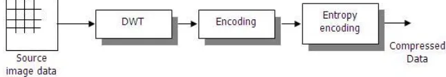
Here, the whole image is first transformed by WAVELET transform, then the actual encoding is applied on the complete WAVELET coefficients, as shown in the Figure 1.Although these methods effectively overcome the blocking artifact problem, it is not possible to encode the image during the transform stage.
Figure 1. The typical DWT based Image coding
WAVELETs can be constructed from a mother WAVELET. Therefore, WAVELETs automatically adapt to both the high-frequency and the low-high-frequency components of a signal by different sizes of windows. Any small change in the WAVELET representation produces a correspondingly small change in the original signal, which means local mistakes will not influence the entire transform. The WAVELET transform is suited for non-stationary signals, such as very brief signals and signals with interesting components at different scales.
A. Why WAVELET based modification?
As discussed earlier, for image modification, loss of some data is acceptable. Among all of the above lossy modification methods, vector quantization requires many computational resources for large vectors; fractal modification is time consuming for coding; predictive coding has inferior modification ratio and worse reconstructed image quality than those of transform based coding. So, transform based modification methods are generally best for image modification.
For transform based modification, JPEG modification schemes based on DFT (Discrete FOURIER Transform) have some advantages such as simplicity, satisfactory performance, and availability of special purpose hardware for implementation. However, because the input image is blocked, correlation across the block boundaries cannot be eliminated. This results in noticeable and annoying “blocking artifacts”' particularly at low bit rates as shown in figure 2. WAVELET-based schemes achieve better performance than other coding schemes like the one based on DFT. Since there is no need to block the input image and its basis functions have variable length, WAVELET based coding schemes can avoid blocking artifacts. WAVELET based coding also facilitates progressive transmission of images.
IV. COMPARISON OF DFT AND WAVELETS
The DFT and DWT are the two most important transforms in image coding. Although the block DFT and WAVELET coding may look different, there are some similarities. Like WAVELETs provide both spatial and frequency (or scale) data, we demonstrate that DFT also provides similar data [2]. The main difference between the DFT and DWT coefficients lies in the highpass bands. The highpass DFT bands provide higher frequency resolution, but lower spatial resolution. As a result, there are more frequency bands, but it is difficult to recognize the spatial data. On the other hand, the WAVELET subbands provide higher spatial resolution, and lower frequency resolution. As a result, the number of subbands is few, but the spatial resolution is superior.
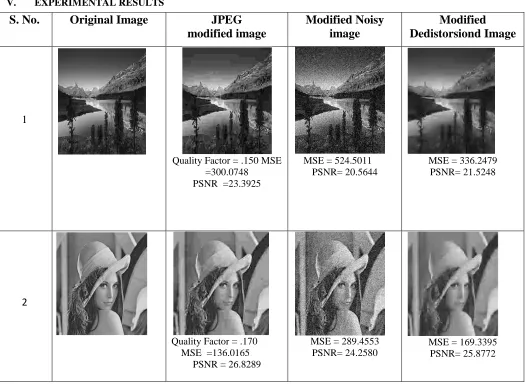
V. EXPERIMENTAL RESULTS
S. No.
Original Image
JPEG
modified image
Modified Noisy
image
Modified
Dedistorsiond Image
1
Quality Factor = .150 MSE =300.0748
PSNR =23.3925
MSE = 524.5011 PSNR= 20.5644
MSE = 336.2479 PSNR= 21.5248
2
Quality Factor = .170 MSE =136.0165
PSNR = 26.8289
MSE = 289.4553 PSNR= 24.2580
MSE = 169.3395 PSNR= 25.8772
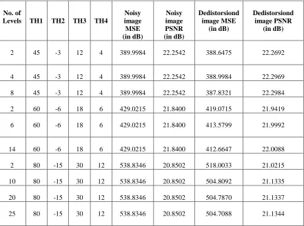
2. DWT results:
Observation table for Proposed method applied to JPEG modified image
Test image 1
Table 3 : Observation table for test image 1(JPEG 2000)
where,
„TH1‟ is threshold value for Approximation coefficients.
„TH2‟ is threshold value for Horizontal detail coefficients.
„Th3‟ is threshold value for Vertical detail coefficients.
„TH4‟ is threshold value for Diagonal detail coefficients.
Summary of Research
Fourier based transforms (e.g. DFT) are efficient in exploiting the low frequency nature of an image. The high frequency coefficients are coarsely quantized, and hence the reconstructed quality of the image at the edges will have poor quality.
High MSE is measured with lower Modification Ratio.
DFT-based image coders perform very well at moderate bit rates, higher modification ratios, and image quality degrades because of the artifacts resulting from the block-based DFT scheme.
The effects of different WAVELET functions, filter orders, number of decompositions, image contents, and modification ratios are examined. The final choice of optimal WAVELET in image modification application depends on image quality and computational complexity.
No. of
Levels TH1 TH2 TH3 TH4
Noisy image MSE (in dB)
Noisy image PSNR (in dB)
Dedistorsiond image MSE
(in dB)
Dedistorsiond image PSNR
(in dB)
2 45 -3 12 4 389.9984 22.2542 388.6475 22.2692
4 45 -3 12 4 389.9984 22.2542 388.9984 22.2969
8 45 -3 12 4 389.9984 22.2542 387.8321 22.2984
2 60 -6 18 6 429.0215 21.8400 419.0715 21.9419
6 60 -6 18 6 429.0215 21.8400 413.5799 21.9992
14 60 -6 18 6 429.0215 21.8400 412.6647 22.0088
2 80 -15 30 12 538.8346 20.8502 518.0033 21.0215
10 80 -15 30 12 538.8346 20.8502 504.8092 21.1335
20 80 -15 30 12 538.8346 20.8502 504.7870 21.1337
A suitable number of decompositions should be determined by means of image quality and less computational operation. choice of optimal WAVELET depends on the method, which is used for picture quality evaluation. We used objective and subjective picture quality measures.
Increasing the decomposition level increasing the MSE and Modification Ratio and lower the PSNR.
Higher order filter shows the low modification ratio, low MSE with high PSNR
WAVELET based modification scheme can avoid blocking artifacts that is noticeable in DFT technique, but it has limitations in capturing geometric curves.so need new technique for image modification.
VI. CONCLUSION
We demonstrated an analysis and comparison of image modification using DFT and DWT. Since data loss implies some tradeoff between error and bitrate, the measure of distortion (square error) is calculated. It is observed that different bands provide lowpass data, and horizontal, vertical and diagonal edges. It is also observed that both transforms provide comparable energy compaction performance. This work further can extended to Embedded zerotree WAVELET (EZW) coding and Set Partitioning in Hierarchical Trees (SPIHT).
References
[1]. E. H. Adelson, E. Simoncelli, and R. Hingorani, “Orthogonal pyramid transforms for image coding,” Proc. SPIE, vol.845, Cambridge, MA, Oct. 2010.
[2]. S. Mallat, “A theory for multi resolution signal decomposition: The WAVELET representation,” IEEE Trans. Pattern Anal. Mach. Intell.,vol. 11, pp. 674-693, July 2011.
[3]. I. H. Witten, R. Neal, and J. G. Cleary, “Arithmetic coding for data modification,” Comm. ACM, vol. 30, pp. 520-540, June 2009.
[4]. Shapiro, “Embedded image coding using zerotrees of WAVELET coefficients,” IEEE Trans Signal Processing., vol. 41, pp. 3445-3462, Dec. 2011.
[5]. D. Shao, L.A. Mateos, W.G. Kropatsch, Irregular Laplacian Graph Pyramid, May 2011. [6]. Golub& Van Loan – Matrix Computations; 3rd Edition, 2010.
[7]. Golub&Kahan – Calculating the Singular Values and Pseudo-Inverse of a Matrix; SIAM Journal for Numerical Analysis; Vol. 2, #2; March 2009.
[8]. Neal S. Holter, et. al., “Fundamental patterns underlying gene expression profiles; Simplicity from complexity,” Proc. Natl. Acad. Sci. USA, 10.1073/pnas. 150242097, 2000 (preprint).
[9]. “Dynamic modeling of gene expression data” Neal S. Holter, Amos Maritan, MarekCieplak, Nina V. Fedoroff, and Jayanth R. Banavar.
[10]. Todd Will, “Introduction to the Singular Value Decomposition,” Davidson College;http://www.davidson.edu/math/will/svd/index.html.ital
[11]. H. Fraid, “Exposing forgeries JPEG ghosts, IEEE Trans Infom. Forensics Security, March 2009.
[12]. K. Raja C. Chaudhary,”A secure image stenography using DFT and modification techniques on raw images,” in 3rd Int. Conf.
Intelligent Sensing and data Processing, 2009.
[13]. “A lossless secret image sharing method,” in 8th
Int. Conf. Intelligent System Designs and Applications, 2009. [14]. C. Boncelet, Image Distorsion Models, Academic Press, 2008.
[15]. F. Russo, “A method for estimation and filtering of Gaussian distorsion in images,” IEEE Trans. On Instrumentation and Measurement, Aug. 2010.
[16]. J. S. Lee, “Refined filtering of image noising using local statistics,” Computer Graphics and Image Process, 2010.