R E S E A R C H
Open Access
Performance evaluation of variable
transmission rate OFDM systems via
network source coding
Te-Lung Kung
*and Keshab K Parhi
Abstract
Studies related to the network source coding have addressed rate-distortion analysis in both noiseless and noisy channels. However, to the best of authors’ knowledge, no prior work has studied network source coding in the context of orthogonal frequency division multiplexing (OFDM) systems. In addition, the system performance using network source coding schemes also remains unknown. In this article, we first propose two variable transmission rate (VTR) OFDM systems by utilizing network source coding schemes, and then evaluate the system performance of these two proposed VTR-OFDM systems. For the proposed VTR single-input single-output OFDM system, we employ the concept of a network with intermediate nodes to develop a 3-stage encoder/decoder, and the proposed encoder provides three different coding rates from 0.5 to 0.8. As for the proposed VTR multi-band OFDM system, two correlated sources are simultaneously transmitted using the multiterminal source coding schemes, and two sources are encoded by different coding rates from 0.25 to 0.5. Finally, compared with the traditional uncoded OFDM system, the proposed VTR-OFDM systems have at least 1 to 4 dB gain in signal-to-noise ratio to achieve the same symbol error rate in the additive white Gaussian noise channel.
Keywords: Network source coding, Single-input single-output OFDM, Multiterminal source coding, Multi-band OFDM, Variable transmission rate
1 Introduction
The rapid growth of communications systems for video, voice, and cellular telephone justifies great demands for mobile multimedia [1,2]. These multimedia services will require high data rate transmissions over broadband radio channels. Due to the limited spectral resource, it is impractical to increase the bandwidth for data trans-mission. In the case of wired networks, high data rate services are not a problem due to the channel charac-teristic; however, high data rate transmissions lead to an additional technical consideration for wireless communi-cations networks. Moreover, the further development of the advanced network technologies is constrained by the amount of information that can be sent through the cor-responding networks. In wired or wireless network, where
*Correspondence: [email protected]
Department of Electrical and Computer Engineering, University of Minnesota, Minneapolis, MN, 55455, USA
bandwidth is strictly limited, it is imperative to use effi-cient data representations or source codes for optimizing network system performance [3,4]. In order to transmit data stream over communications networks with limited bandwidth, network source coding can be used to solve this problem.
Network source coding expands the data compression problem for networks beyond the point-to-point net-work introduced by Shannon [5]. These include netnet-works with multiple transmitters, multiple receivers, decoder side information, intermediate nodes, and any combi-nation of these features. Thus, network source coding attempts to bridge the gap between point-to-point net-work and recent complicated netnet-work environments. Net-work source coding is a promising technique that provides many advantages, including source dependence, func-tional demands, and resource sharing [6-12]. By utilizing network source coding, the system performance can be improved by using correlated sources. This leads to an
adjustable transmission rate, and the input data streams share the entire network resource during the transmis-sion. If decoders have the information about the rela-tion of transmitted data sources, the input data sources can be reconstructed without any loss in the noiseless channel.
High data rate wireless communications are limited not only by noise but also by the inter-symbol interference (ISI) from the dispersion of the wireless communications channel. Orthogonal frequency division multiplexing (OFDM) systems have been adopted in various wire-less communications standards due to their high spec-trum efficiency and robustness against the frequency selective fading channels [1,13]. In addition, OFDM is a prominent technique suitable for high data rate transmis-sions in multicarrier communications systems, because of the potential to either partially reduce or completely eliminate the adverse ISI effect. In OFDM systems, a wideband channel is converted to a set of narrowband subchannels, and the data is transmitted using all sub-channels. Multi-band OFDM (MB-OFDM) systems group all subchannels into multiple subbands, and then trans-mit data in different subbands simultaneously [14,15]. Hence, the multi-band signal processing technique can be viewed as either a multiple access scheme that allo-cates subbands to transmit different users’ data at the same time or an approach to employ the frequency diver-sities for data transmission in order to improve the system performance.
To the best of authors’ knowledge, the following prop-erties have not been demonstrated yet [6-12,16]: (1) the variable transmission rate (VTR) OFDM communi-cations systems using network source coding, and (2) the performance improvement after applying the net-work source coding to OFDM systems. In this article, two VTR-OFDM communications systems are proposed to evaluate the performance of network source coding schemes. First, a VTR single-input single-output OFDM (VTR-SISO-OFDM) system is proposed. The proposed system generates different transmission rates using a pro-posed 3-stage encoder. Functions implemented in this 3-stage encoder determine the codebook sizes for storage and the achievable rates for data transmission. The pro-posed 3-stage encoder consists of three different mapping functions and their corresponding encoders using arith-metic coding scheme. The performance of the VTR-SISO-OFDM system based on the proposed 3-stage encoder is evaluated. Then, a VTR multi-band OFDM (OFDM) system is proposed. The proposed VTR-MB-OFDM system transmits two correlated sources using the multiterminal source coding scheme [7,17-19]. The transmission rates are adjusted based on four switch configurations at the transmitter, and 16 switch con-figurations control the information interchanges during
the entire data transmission. The performance of the proposed VTR-MB-OFDM system for these 16 switch configurations is evaluated. We then analyze the variable transmission bit rate for these two proposed systems. The advantages of the proposed systems include availability of different transmission rates, abilities of different users to share the network resource, and robustness in wire-less communications environments. Moreover, compared with the traditional uncoded OFDM systems, simula-tion results show the proposed systems obtain at least 1 to 4 dB gain in signal-to-noise ratio (SNR) to achieve the same symbol error rate (SER) in the additive white Gaussian noise (AWGN) channel. In addition, the rate factors of these two proposed systems vary from 0.55 to 0.96.
The rest of the article is organized as follows. In Section 2, a VTR-SISO-OFDM communications system is proposed. A VTR-MB-OFDM system based on the multi-terminal source coding scheme is proposed in Section 3. Performance analysis and simulation results are pre-sented in Section 4. Finally, the article is concluded in Section 5.
2 The VTR-SISO-OFDM system
We propose a VTR-SISO-OFDM system with three different transmission rates in this section. The main goal of the proposed VTR-SISO-OFDM system is to design a variable transmission rate system and to recover the source data with the help of the side informa-tion. A 3-stage encoder is proposed in Section 2.1. In Section 2.2, the feasibilities of functions used in the encoder and the variable transmission rates of the proposed VTR-SISO-OFDM system are discussed. Finally, the corresponding decoder is described in Section 2.3.
2.1 The 3-stage encoder of the VTR-SISO-OFDM system Figure 1a shows the 3-stage encoder of the proposed VTR-SISO-OFDM system. LetLsymbols be transmitted. Let aT,bT,cT, anddTbe discrete random variables, whereaT is the source data,bT,cT, anddTrepresent the side infor-mation, and aT, bT, cT, and dT are independent. Con-sider the source data{ai}is independently selected from the set {1, 2,. . .,A}, where aT =[a1,a2,. . .,aL]= {ai}, i ∈ {1, 2,. . .,L},iis the sample index, the probability of aT is
p(aT)= L
i=1
p(ai), (1)
Figure 1The 3-stage encoder/decoder of the proposed VTR-SISO-OFDM system.Figure 1 represents the proposed 3-stage(a)encoder/(b) decoder in the proposed VTR-SISO-OFDM system. The proposed 3-stage encoder in Figure 1a consists of source data, mapping functions, and the side information. We utilize a specific switch to select different transmission rates. For the proposed 3-stage decoder in Figure 1b, the source data is reconstructed using reversible mapping functions and the side information.
[d1,d2,. . .,dL]= {di}, the probabilities ofbT,cT, anddT are given by:
p(bT)= L
i=1 p(bi)
p(cT)= L
i=1 p(ci)
p(dT)= L
i=1 p(di),
(2)
and{bi},{ci}, and{di}are randomly chosen from the sets
{1, 2,. . .,B},{1, 2,. . .,C}, and{1, 2,. . .,D}, respectively. In
Figure 1a, the output symbolswT = {wi},kT = {ki}, and
eT = {ei}are
wi=f(ai,bi)∈ {min(f(i1,j1)),. . ., max(f(i1,j1))} =m ki=g(wi,ci)∈ {min(g(mi2,j2)),. . ., max(g(mi2,j2))} =y ei=h(ki,di)∈ {min(h(yi3,j3)),. . ., max(h(yi3,j3))} =o,
(3)
wheref(·),g(·), andh(·)are injective or surjective func-tions, i1 ∈ {1, 2,. . .,A}, j1 ∈ {1, 2,. . .,B}, i2 ∈
{1, 2,. . .,W}, j2 ∈ {1, 2,. . .,C},i3 ∈ {1, 2,. . .,K}, j3 ∈
elements inm,y, ando, respectively. Iff(·),g(·), andh(·) are injective functions, the probabilities ofwi,ki, andeiare given by:
p(wi)=p(f(ai,bi))=p(ai,bi)
p(ki)=p(g(wi,ci))=p(ai,bi,ci)
p(ei)=p(h(ki,di))=p(ai,bi,ci,di),
(4)
and the corresponding entropies are
H(wi)= A
i1=1 B
j1=1
−p(f(i1,j1))·log2(p(f(i1,j1)))
H(ki)= W
i2=1 C
j2=1
−p(g(mi2,j2))·log2(p(g(mi2,j2)))
H(ei)= K
i3=1 D
j3=1
−p(h(yi3,j3))·log2(p(h(yi3,j3))),
(5)
wherep(f(i1,j1))is the probability of the outcomef(i1,j1), p(ai,bi) is the joint probability of(ai,bi),mi2 means the i2th element inm, andyi3 means thei3th element iny. In addition, iff(·),g(·), andh(·)are surjective functions, the probabilities ofwi,ki, andeiare given by:
p(wi=i2)= A
i1=1 p(i1)·
⎧ ⎨ ⎩
B
j1=1
p(j1|f(i1,j1)=i2)
⎫ ⎬ ⎭
p(ki=i3)= W
i2=1 p(i2)·
⎧ ⎨ ⎩
C
j2=1
p(j2|g(i2,j2)=i3)
⎫ ⎬ ⎭
p(ei=i4)= K
i3=1 p(i3)·
⎧ ⎨ ⎩
D
j3=1
p(j3|h(i3,j3)=i4)
⎫ ⎬ ⎭,
(6)
and the corresponding entropies are
H(wi)= W
i2=1
−
⎡ ⎣A
i1=1 p(i1)·
⎧ ⎨ ⎩
B
j1=1
p(j1|f(i1,j1)=i2)
⎫ ⎬ ⎭ ⎤ ⎦
·log2
⎛ ⎝A
i1=1 p(i1)·
⎧ ⎨ ⎩
B
j1=1
p(j1|f(i1,j1)=i2)
⎫ ⎬ ⎭ ⎞ ⎠
H(ki)= K
i3=1
−
⎡ ⎣W
i2=1 p(i2)·
⎧ ⎨ ⎩
C
j2=1
p(j2|g(i2,j2)=i3)
⎫ ⎬ ⎭ ⎤ ⎦
·log2
⎛ ⎝W
i2=1 p(i2)·
⎧ ⎨ ⎩
C
j2=1
p(j2|g(i2,j2)=i3)
⎫ ⎬ ⎭ ⎞ ⎠
H(ei)= E
i4=1
−
⎡ ⎣K
i3=1 p(i3)·
⎧ ⎨ ⎩
D
j3=1
p(j3|h(i3,j3)=i4)
⎫ ⎬ ⎭ ⎤ ⎦
·log2
⎛ ⎝K
i3=1 p(i3)·
⎧ ⎨ ⎩
D
j3=1
p(j3|h(i3,j3)=i4)
⎫ ⎬ ⎭ ⎞ ⎠, (7)
where i4 ∈ {1, 2,. . .,E} and p(j1|f(i1,j1) = i2) is the conditional probability.
From Equation (4), if f(·), g(·), and h(·) are injective functions, we do not need any extra information to recon-structai,wi, andki. However, from Equation (6), iff(·), g(·), and h(·) are surjective functions, the extra infor-mation is needed to create an one-to-one relationship between each input pair and the output symbol. There-fore, the actual input symbols ai, wi, and ki could be retrieved based on the extra information. For example, considerf(·)is a surjective function, where
f(ai,bi)= |ai−bi|. (8)
AssumeA > 4,B > 4,L = 3,aT =[ 1, 3, 2], andbT = [ 2, 2, 3]. Then, we have
f(a1=1,b1=2)=f(a2=3,b2=2)
=f(a3=2,b3=3)=1 f(1, 2)=f(2, 3)= | −1| =1
f(3, 2)= |1| =1
wT =[ 1, 1, 1] .
(9)
Without any extra information,
a1=f−1(w1,b1)=f−1(1, 2)=δ1
a2=f−1(w2,b2)=f−1(1, 2)=δ1
a3=f−1(w3,b3)=f−1(1, 3)=δ2,
(10)
whereδ1could be 1 or 3 andδ2could be 2 or 4. Thus,aT is given by:
aT ∈ {[ 1, 1, 2] , [ 1, 1, 4] , [ 1, 3, 2] , [ 1, 3, 4] ,
[ 3, 1, 2] , [ 3, 1, 4] , [ 3, 3, 2] , [ 3, 3, 4]}. (11)
From Equation (9), in order to obtain the correct input symbol ai, the extra information could be chosen by satisfying:
where 1 is a set and 1 contains sample indexi that satisfies(ai−bi) <0. Based on Equation (12), we have
1= {1, 3}. (13)
Therefore, with the help of the extra information, the input symbol is reconstructed by
ai=f−1(wi,bi,1) ai=bi−wi, i∈1 ai=bi+wi, i∈1.
(14)
Based on Equation (14), we have
a1=f−1(1, 2,i∈1)=1
a2=f−1(1, 2,i∈1)=3
a3=f−1(1, 3,i∈1)=2
aT =[ 1, 3, 2] .
(15)
Moreover, if g(·) and h(·) are surjective functions, 2 and3are the corresponding extra information to obtain wi=g−1(ki,ci,2)andki=h−1(ei,di,3), respectively.
AfterwT,kT, andeT are generated, we apply the arith-metic coding scheme to encode each symbol in these data streams. First, we considerf(·),g(·), andh(·)are injective functions. Codebooks for different arithmetic encoders are Qt, where t ∈ {1, 2, 3}. In Equation (16), Qt con-tains the information of all possible input source data, side information, probabilities for each possible outcome, and the corresponding binary codeword as follows:
Q1(l1, :)=
(i1,j1),f(i1,j1),p(f(i1,j1)),xTf(i1,j1)
Q2(l2, :)=
(mi2,j2),g(mi2,j2),p(g(mi2,j2)),x T g(mi2,j2)
Q3(l3, :)=
(yi3,j3),h(yi3,j3),p(h(yi3,j3)),xTh(yi3,j3)
l1=(i1−1)×B+j1 l2=(i2−1)×C+j2 l3=(i3−1)×D+j3
(16)
where l1, l2, andl3 are the row indices, Q1(l1, :) means thel1th row inQ1,xTf(i1,j1)is the codeword corresponding to the outcomef(i1,j1), and the numbers of possible out-comes inQ1,Q2, andQ3areA×B,W ×C, andK×D. In addition, how to generate the encoded bit streamxT depends on the selected switch, where
xT ∈xTf(aT,bT),xg(TwT,cT),xTh(kT,dT)
, (17)
f(aT,bT) = {f(ai,bi), ∀i}, g(wT,cT) = {g(wi,ci), ∀i}, andh(kT,dT)= {h(ki,di), ∀i}. From Equation (16), if we introduce more and more stages in the encoder, the Ham-ming distances between any two adjacent codewords at the output of higher stages become smaller and smaller.
The encoding rates (Renc,St) of the 3-stage encoder are
Renc,S1 = A
i1=1 B
j1=1
1+ −log2p(i1,j1)
·p(i1,j1)
Renc,S2 = W
i2=1 C
j2=1
1+ −log2p(mi2,j2)
·p(mi2,j2)
Renc,S3 = K
i3=1 D
j3=1
1+ −log2p(yi3,j3)
·p(yi3,j3).
(18)
Moreover, the 3-stage encoder provides three different lengths ofxT, because the numbers of possible outcomes in wT, kT, and eT are different. These three different lengths ofxTare
LenS1= L
i=1
LenxTf(a i,bi)
=
L
i=1
1+ −log2p(ai,bi)
LenS2= L
i=1
LenxTg(w i,ci)
=
L
i=1
1+ −log2p(ai,bi,ci)
LenS3= L
i=1 Len
xTh(ki,di)
=
L
i=1
1+ −log2p(ai,bi,ci,di).
(19)
If f(·), g(·), and h(·) are surjective functions, the code-booksQt, the encoding rates (Renc,St), and three lengths of
xTare different from Equations (16), (18), and (19). There-fore, we utilize the probabilitiesp(wi = i2),p(ki = i3), andp(ei = i4)in Equation (6) to derive the correspond-ing codebooks, encodcorrespond-ing rates, and different lengths of the encoded bit streams for surjective functions. First, the codebooksQtare
Q1(l1, :)=
(i1,j1),f(i1,j1),p(wi=i2),xTwi
Q2(l2, :)=
(mi2,j2),g(mi2,j2),p(ki=i3),x T ki
Q3(l3, :)=
(yi3,j3),h(yi3,j3),p(ei=i4),x T ei
l1=(i1−1)×B+j1 l2=(i2−1)×C+j2 l3=(i3−1)×D+j3.
Then, the encoding rates (Renc,St) are given by:
Renc,S1 = W
i2=1
1+ −log2p(wi=i2)
·p(wi=i2)
Renc,S2 = K
i3=1
1+ −log2p(ki=i3)
·p(ki=i3)
Renc,S3 = E
i4=1
1+ −log2p(ei=i4)
·p(ei=i4).
(21)
Finally, three different lengths ofxT are
LenS1 = L
i=1
LenxTf(a i,bi)
=
L
i=1
1+ −log2p(wi=i2)
LenS2 = L
i=1 Len
xTg(wi,ci)
=
L
i=1
1+ −log2p(ki=i3)
LenS3 = L
i=1 Len
xTh(ki,di)
=
L
i=1
1+ −log2p(ei=i4)
.
(22)
From Equations (19) and (22), the proposed 3-stage encoder generates three different transmission rates by selecting different output signals through varying the switchSt.
In communications systems, two different ways utilized to transmit the data are continuous data transmission and packet data transmission. For the continuous data trans-mission such as voice, the transtrans-mission rate is controlled by the transport layer. In this case, the receiver knows the transmission rate during the entire data flow. As for the packet data transmission, each packet consists of the header and the data, and the information of the switch configuration can be hidden in the header of each packet. Therefore, in order to adjust the transmission rate with-out notifying the receiver, the transmitter first encodes the switch configuration and then includes the encoded bits in the header. The length of the header depends on the cod-ing rate of the error correctcod-ing codes. In this article, we consider continuous data transmission.
After the entire encoding process, we pad the input data, xT, with a certain number of zeros (Nz) to maintain the total number of bits (Nb) equal toM×NT, whereNz =
M×NT −LenSt,Mis the number of bits to represent a
symbol, andNT is the number of total subcarriers. Then, the modified bit stream, [xT 01×Nz], is transmitted using
a SISO-OFDM system.
2.2 The feasibilities of functions and variable transmission rate analysis
Choosing the proper mapping functions in the encoder provides two advantages: (1) the improvement of the system performance and (2) the adjustability of the trans-mission rate. In order to reduce the size of codebook and to reconstruct the source data perfectly at the receiver, it is necessary to choose the mapping functions that generate smaller cardinalities in the encoder. Also, the help of the extra information provides us much more feasible ways to choose the mapping functions without any constraint.
The variable transmission bit rates (Rb,St) of the
pro-posed VTR-SISO-OFDM system are
Rb,St=fs×M× Nu NT+NCP
Nu=
LenSt M
,
(23)
where fs is the sampling rate,Nu is the number of used subcarriers,NCP is the length of cyclic prefix, and·is the ceiling function. The rate factor, Nu
NT, is derived from Rb,St
Rb,raw, whereRb,rawis the raw transmission rate,Rb,raw = fs×M× NTN+TNCP, andNNuT < 1. From Equation (23), the transmission rate can be adjusted by varying the num-ber of used subcarriers,Nu. Moreover, the probability of each possible outcome affects the number of used sub-carriers. Thus, the smaller the probability of each possible outcome, the higher the transmission rate. In Figure 1a, if the maximal transmission rate is achieved from the output bit stream through the switchS3, the probability of each possible outcome isp(i1,j1,j2,j3), wheref(·),g(·), andh(·) are injective functions. Furthermore, the operation band-width of the proposed VTR-SISO-OFDM system depends on the switchSt, and the variable operation bandwidths (BWSt) for the proposed VTR-SISO-OFDM system are
BWSt =Nu×f
=
LenSt M
× BW
NT
, (24)
wheref is the subcarrier spacing,f = BWN
T, andBWis
the original operation bandwidth.
Figure 1b shows the proposed 3-stage decoder in the VTR-SISO-OFDM system. First, the receiver utilizes the switch configuration assigned by the transport layer to determine the decoding route. For example, ifS3=1, the decoder closes the switchS3, and proceeds to decodex˜T. The side informationdThelps the arithmetic decoder 3 to perform the first stage decoding process. In the first stage, the arithmetic decoder 3 decodesx˜T based on the mini-mum Hamming distance rule with the aid ofQ3anddT. Then,wˇT is generated through performingg−1(·)onkˇT, cT, and2. Finally, we obtain the estimated source data
ˇ
aT after performing the inverse functions f−1(·) on the estimated sequencewˇT, the side informationbT, and the extra information1as shown in Equation (25).
ˇ
aT =f−1(wˇT,bT,1)
=f−1(g−1(kˇT,cT,2),bT,1), (25)
where f−1(wˇT,bT,
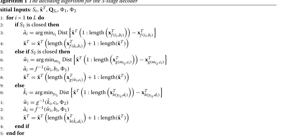
1) = {f−1(wˇi,bi,1),∀i} and g−1(kˇT,cT,2) = {g−1(kˇi,ci,2),∀i}. The entire decod-ing procedure is listed in Algorithm 1. In Algorithm 1, Dist{·}is the Hamming distance ands(i : j)means from theith sample to thejth sample ins.
3 The VTR-MB-OFDM system
In this section, a VTR-MB-OFDM system is proposed using the multiterminal source coding scheme. The main goal of the proposed VTR-MB-OFDM system is to design a variable transmission rate system and to evaluate the system performance under different conditions.
3.1 The proposed VTR-MB-OFDM system and transmission rate analysis
The proposed VTR-MB-OFDM system is shown in Figures 2 and 3. In Figure 2, correlated information sequences aT and bT are generated by repeated inde-pendent drawings of a pair of discrete random variables, whereaT =[a1,a2,. . .,aL]= {ai},bT =[b1,b2,. . .,bL]=
{bi},ai ∈ {1, 2,. . .,A},bi ∈ {1, 2,. . .,B},i ∈ {1, 2,. . .,L}, andLis the total number of drawings. In the proposed VTR-MB-OFDM system, fˆ(·) is an injective function. Thus, the entropies of fˆ(ai,S2 · bi) and fˆ(S1 · ai,bi) are
H(fˆ(ai,S2·bi))
=
⎧ ⎪ ⎪ ⎪ ⎨ ⎪ ⎪ ⎪ ⎩
A i1=1−
p(i1)·log2(p(i1)), if S2=0,
A i1=1
B j1=1−p
(i1,j1)·log2(p(i1,j1)), if S2=1,
H(fˆ(S1·ai,bi))
=
⎧ ⎪ ⎪ ⎨ ⎪ ⎪ ⎩
B j1=1−p
(j1)·log2(p(j1)), if S1=0,
A i1=1
B j1=1−
p(i1,j1)·log2(p(i1,j1)), if S1=1.
(26)
X-encoder encodesfˆ(aT,S2·bT)toxTencusing the arith-metic coding scheme, where the functionfˆ(·)maps each pair(ai,S2·bi)in(aT,S2·bT)to an unique value and the
Algorithm 1The decoding algorithm for the 3-stage decoder
Initial Inputs:St,x˜T,QSt,1,2 1: fori= 1toLdo
2: ifS1is closedthen 3: aˆi=arg mini1Dist
˜
xT
1 : lengthxTf(i 1,bi)
−xTf(i 1,bi)
4: x˜T = ˜xT
lengthxTf(aˆ
i,bi)
+1 : length(x˜T)
5: else ifS2is closedthen 6: w˜i=arg minmi2Dist
˜
xT
1 : lengthxTg(mi 2,ci)
−xTg(mi 2,ci)
7: a˜i=f−1(w˜i,bi,1)
8: x˜T = ˜xT
length
xTg(w˜
i,ci)
+1 : length(x˜T)
9: else
10: kˇi=arg minyi3Dist
˜
xT
1 : length
xTh(y
i3,di)
−xTh(y
i3,di)
11: wˇi=g−1(kˇi,ci,2) 12: aˇi=f−1(wˇi,bi,1)
13: x˜T = ˜xT
lengthxT
h(kˇi,di)
+1 : length(x˜T)
14: end if
Figure 2The transmitter in the proposed VTR-MB-OFDM communications system.Figure 2 represents the transmitter in the proposed VTR-MB-OFDM communications system. This proposed transmitter consists of a correlated source generator, a system architecture applying the multiterminal source coding, and the multi-band OFDM system.
length ofxTencdepends onS2. Codebooks,QxandQy, used to generatexTencandyTencare
Qx(γ1, :)=
(α1,β1),fˆ(α1,β1),p(fˆ(α1,β1)),xTfˆ(α 1,β1)
Qy(γ2, :)=
(α2,β2),fˆ(α2,β2),p(fˆ(α2,β2)),yTˆ
f(α2,β2)
γ1=β1×A+α1
γ2=α2×B+β2,
(27)
where γ1andγ2are the row indices,α1 ∈ {1, 2,. . .,A}, β1 ∈ {0, 1,. . .,B},α2 ∈ {0, 1,. . .,A}, β2 ∈ {1, 2,. . .,B},
xTˆ
f(α1,β1) and y T ˆ
f(α2,β2) are the codewords corresponding to the possible outcomesfˆ(α1,β1) andfˆ(α2,β2), xTenc = xTˆ
f(aT,S
2·bT), andy T
enc = yTfˆ(S1·aT,bT). In order to satisfy the
criterion of digital modulation, a zero vector is padded to the back ofxTencsuch that
xTzp= ⎧ ⎨ ⎩
xTenc,if mod(X,M)=0,
xTenc01×(M−mod(X,M))
,if mod(X,M)=0,
(28)
whereXis the length ofxTenc,Mis the number of bits to represent a symbol, mod([M− mod(X,M)] ,M) is the length of the zero padding vector, the length ofxTzpis X+ mod([M− mod(X,M)] ,M),Xis
X= ⎧ ⎪ ⎨ ⎪ ⎩ L i=1
1+ −log2p(ai), if S2=0,
L i=1
1+ −log2p(ai,bi)
, if S2=1,
(29)
and the encoding rate (Renc,x[S2]) of X-encoder is
Renc,x[0]= A
i1=1
1+ −log2p(i1)
·p(i1),
Renc,x[1]= A
i1=1 B
j1=1
1+ −log2p(i1,j1)
·p(i1,j1).
(30)
AfterxTzpis modulated, we obtainxTmod, and the bandwidth of the 1stband occupied byxT
modis
BW1st =
X M
·f. (31)
Y-encoder performs the same procedures to obtainyTenc by replacingfˆaT,S
2·bT
tofˆS1·aT,bT
. Then we pad a zero vector with length mod([M− mod(Y,M)] ,M) to the back ofyTencin order to generateyTzp. The length of yTzpisY+ mod([M− mod(Y,M)] ,M). In addition, the length ofyTenc,Y, is
Y = ⎧ ⎪ ⎨ ⎪ ⎩ L i=1
1+ −log2p(bi)
, if S1=0,
L i=1
1+ −log2p(ai,bi)
, if S1=1,
(32)
and the encoding rate (Renc,y[S1]) of Y-encoder is
Renc,y[0]= B
j1=1
1+ −log2p(j1)
·p(j1),
Renc,y[1]= A
i1=1 B
j1=1
1+ −log2p(i1,j1)
·p(i1,j1).
(33)
Thus, the bandwidth of the 2ndband is equal to
BW2nd=
Y M
·f. (34)
From Equations (30) and (33), when S1 and S2 are equal to one, the lengths of two encoded bit streams,X
andY, are identical; moreover, the allocated bandwidths of these two subbands, BW1st and BW2nd, are also the
same.
Two serial-to-parallel (S/P) convertors are applied to xTmod andyTmod before theNT-point inverse fast Fourier transform (IFFT) operation. Then, in order to perform a NT-point IFFT operation, we insert a null band occupy-ingNnullsubcarriers, where Nnull = NT − MX − MY. After theNT-point IFFT operation,sTPSis obtained using a parallel-to-serial (P/S) convertor. A cyclic prefix (CP) with lengthNCPis inserted to the front ofsTPSin order to reduce the ISI. Finally,sTis transmitted using the radio frequency (RF) components, where
sT = ⎧ ⎨ ⎩
sTPS(i+NT−NCP), i=0, 1,. . .,NCP−1
sTPS(i), i=0, 1,. . .,NT−1
.
(35)
The transmission bit rate of the proposed VTR-MB-OFDM system is related to the switches S1 and S2. Therefore, four different transmission bit rates (Rb,[S1S2]) are
Rb,[0 0]=
!L
i=1[ 1+ −log2p(ai)] M
"
+
!L
i=1[ 1+ −log2p(bi)] M
"#
× M·fs
NT+NCP ,
Rb,[0 1]=
!L
i=1[ 1+ −log2p(ai)] M
"
+
!L
i=1[ 1+−log2p(ai,bi)] M
"#
× M·fs
NT+NCP ,
Rb,[1 0]=
!L
i=1[ 1+ −log2p(ai,bi)] M
"
+
!L
i=1[ 1+ −log2p(bi)] M
"#
× M·fs
NT+NCP ,
Rb,[1 1]=
!L
i=1[ 1+−log2p(ai,bi)] M
"
+
!L
i=1[ 1+−log2p(ai,bi)] M
"#
× M·fs
NT+NCP .
Consider the data is transmitted over the AWGN channel. At the receiver as shown in Figure 3, the received signalrT is
rT =sT+nT, (37)
where nT is the AWGN noise. First, the receiver per-forms the cyclic prefix removal onrT, the S/P operation, and the NT-point FFT operation on rSP. After the FFT operation, symbols allocated in the specific subbands are extracted, and then demodulated by the corresponding signal demapper.xTdemod is generated using the informa-tion from the first MX subcarriers, and yTdemod is also generated using the information from the (MX +1)th subcarrier to the (MX + MY)th subcarrier. Then, xTzr is obtained by removing mod(M− mod(X,M),M) samples at the back of xTdemod, andyTzr is also obtained by removing mod(M − mod(Y,M),M) samples at the back of yTdemod. Let us usexTzr to explain the decod-ing process, andyTzris decoded using the same procedure. X-decoder decodesxTzr by minimizing the Hamming dis-tances between codewords in the codebookQx and the partial bit stream inxTzr with or without help of the side information through the switch S3, and then the esti-mated source data aˆT is obtained. In Algorithm 2, we
describe the overall decoding process used in X-decoder and Y-decoder.
4 Performance analysis and simulation results We evaluate the performance of two proposed VTR-OFDM systems, including the VTR-SISO-VTR-OFDM system and the VTR-MB-OFDM system. Section 4.1 demon-strates the performance of the proposed VTR-SISO-OFDM system, and then the performance of the proposed VTR-MB-OFDM system is demonstrated in Section 4.2.
4.1 Performance evaluation of the VTR-SISO-OFDM system
Assume 10000 packets are transmitted using the VTR-SISO-OFDM system and each packet contains 2000 encoded messages. Consider the source data and the side information follow the same probability distributionp(z),
p(z=λ)= !ZZ−λ+1 λ=1(Z−λ+1)
, (38)
where z is a random variable, z ∈ {1, 2,. . .,Z}, and
!Z
λ=1(Z−λ+1)is the total number of possible outcomes. The source dataaT = {ai}is fed to the 3-stage encoder in order to evaluate the system performance under three
Algorithm 2The decoding algorithm for multiterminal source decoder of the proposed VTR-MB-OFDM system
Initial Inputs:xTzr, yTzr
1: fori= 1toLdo
2: IfSτ = 1, decode the corresponding inputs with the side information; otherwise, decode the corresponding inputs without the side information, whereτ ∈ {3, 4}.
3: ifS4=0then 4: j1=0
5: (aˆi, 0)=arg min(i1,j1)Dist
$ x0zrT
%
1 : length
% xTˆ
f(i1,j1)
&&
−xTˆ
f(i1,j1)
'
6: else
7: j1∈ {0, 1,. . .,B}
8: (aˆi,j1)=arg min(i1,j1)Dist
$ xTzr
%
1 : length
% xTˆ
f(i1,j1)
&&
−xTˆ
f(i1,j1)
'
9: end if
10: ifS3=0then 11: i2=0
12: (0,bˆi)=arg min(i2,j2)Dist
$ yTzr
%
1 : length
% yTˆ
f(i2,j2)
&&
−yTˆ
f(i2,j2)
'
13: else
14: i2∈ {0, 1,. . .,A}
15: (i2,bˆi)=arg min(i2,j2)Dist
$ yTzr
%
1 : length
% yTˆ
f(i2,j2)
&&
−yTˆ
f(i2,j2)
'
16: end if 17: xTzr=xTzr
%
length
% xTˆ
f(a˜i,j1)
&
+1 : lengthxTzr&
18: yTzr=yTzr %
length
% yTˆ
f(i2,b˜i)
&
+1 : length(yTzr)
&
different transmission rates, where L = 2000. Assume A=100, and the maximum values in the side information are given byB=75,C = 50, andD=25 orD= 5. The probability density function (pdf ) of source data,p(ai), is
p(ai=i1)=
A−i1+1 Na
, (39)
whereNa=!100i1=1(100−i1+1)=5050. Then, the pdfs of the side information are
p(bi =j1)=
B−j1+1 Nb
p(ci=j2)=
C−j2+1 Nc
p(di=j3)=
D−j3+1 Nd
,
(40)
whereNb=
!75
j1=1(75−j1+1)=2850,Nc=
!50 j2=1(50− j2+1)=1275, andNd=!Dj3=1(D−j3+1)=325 or 15. The mapping functions in the proposed 3-stage encoder, f(α,β),g(α,β), andh(α,β), are
f(α,β)= mod(α+β,γ ) g(α,β)= |α−β|
h(α,β)=p(α,β),
(41)
where γ is the maximum prime number in A+B and p(α,β)is the joint probability function on (α,β). From Equation (41),f(·)andg(·) are surjective functions, and h(·) represents an injective function. After applying the mapping functions to the input symbols and the side infor-mation at each stage, the corresponding output symbols, wT,kT, andeT, are
wi= mod(ai+bi, 173) ki=|wi−ci|
ei=p(ki,di),
(42)
whereγ =173. Moreover, the cardinalities ofwT,kT, and eT areW = 173, K = 172, andE = 172×25 orE = 172×5 depending on the valueD. Thus, the transmission rate of the output signal at the 2nd stage is the smallest, becauseK is less thanW andE. In addition,1and2 are chosen by satisfying:
1= {i|(ai+bi)=175}
2= {i|(wi−ci) <0}.
(43)
Once the output symbolswT,kT, andeTare generated, we apply arithmetic code to encode each symbol to the specific codeword using the corresponding codebook at each stage. Cardinalities of different codebooksQtused to encode symbols at each stage areA×B,W×C, andE. Two bits for rate adjustment are added to the front of the output in order to construct the input bit stream. Then, we use a SISO-OFDM system with 16-QAM signal map-per/demapper, 8192-point IFFT/FFT (NT = 8192), and
NCP=256 to transmit the data over the AWGN channel. Assume the operating bandwidth of the communications system is 20 MHz, and each sample is generated by a sam-pling frequency 5 MHz. The raw transmission bit rate of this SISO-OFDM system is 19.4 Mbps. In addition, the subcarrier spacing,f, is about 2.441 MHz.
Some system parameters of the proposed VTR-SISO-OFDM system are listed in Table 1, whereS1,S2, andS3 indicate which route we choose. In Table 1, we evaluate the entropies, encoding rates, used subcarriers, occupied bandwidth, and transmission rates. First, we notice that the encoding rates are greater than the entropies at each stage. It is important that the transmission of the proposed VTR-SISO-OFDM system is admissible under this condi-tion. Furthermore, at the first two stages of the encoder, the entropies,H(wi) andH(ki), and the encoding rates, Renc,S1 andRenc,S2, are almost the same, because the car-dinality ofwT is approximately equal to the cardinality of kT. Then, the subcarriers used on average and the trans-mission rates of the output signals at the first two stages are also approximately equal because of this reason. At the third stage, Table 1 also shows that we can obtain higher encoding rates and higher entropies simply by increas-ing D; however, we can also expect that the Hamming distances between each two adjacent codewords become smaller and smaller with increasing D. In addition, we estimate the used subcarriers, the occupied bandwidths, and the transmission rates at each stage usingL·Renc,St
instead of LenSt, because the entire packet transmission is
a stochastic process which means LenStis not a constant,
andRenc,St provides the average codeword length of
pos-sible output data samples. Furthermore, the rate factors,
L·Renc,St
M ·N1T, at different stages are approximately equal
to 0.55, 0.675, and 0.8.
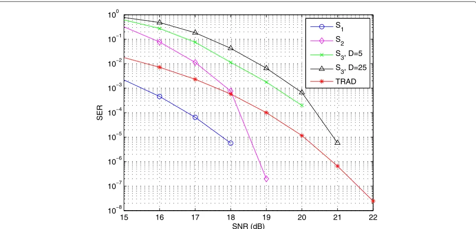
We demonstrate the performance of the proposed VTR-SISO-OFDM system in Figure 4. In Figure 4, the SERs of the proposed VTR-SISO-OFDM system at different
Table 1 System parameters of the proposed VTR-SISO-OFDM system
S1 S2 S3
D=25 D=5
Entropy 7.4346 7.3323 11.7240 9.4815
Encoding rate (bits/sample),Renc,St
9 8.8570 13.2461 11.0735
Averaged number of used subcarrier,(L·Renc,St
M
) 4501 4429 6624 5537
Approximately allocated bandwidth (MHz.),
(L·R
enc,St M
)
·f
11 10.8 16.2 13.5
Transmission bit rate (Mbps),Rb,St=
(L·R
enc,St M
)
· fs·M NT+NCP
15 16 17 18 19 20 21 22 108
107 106 105 104 103 102 101 100
SNR (dB)
SER
S1
S2
S 3, D=5 S3, D=25
TRAD
Figure 4The performance of the proposed VTR-SISO-OFDM communications system at each stage with differentD.
stages, S1, S2, and S3, are compared with the perfor-mance of traditional uncoded OFDM system (TRAD). The SER of traditional uncoded OFDM system implies how many bits are incorrect. For example, under SNR= 19 dB, there are almost four incorrect bits during each packet transmission. If we transmit the data stream using the routeS1, zero SER is achievable when SNR is greater than 19 dB. Although we can transmit data stream with higher rate using the routeS3, there are approximate two incorrect symbols under SNR= 19 dB. Reasons why we have higher SER using the routeS3are the smaller Ham-ming distances between each two adjacent codewords and the error propagation during the entire decoding process. By decreasingD, we obtain better performance with lower transmission rate as shown in Table 1 and Figure 4.
4.2 Performance evaluation of the VTR-MB-OFDM system Assume 10000 packets are transmitted using the pro-posed VTR-MB-OFDM system and each packet con-tains 2000 correlated information sequences, aT and bT. After the correlated sequences are generated, we apply the multiterminal source coding to encode aT andbT with or without the side information from each other, and then these 2000 correlated sequences are transmitted using two different subbands in MB-OFDM system. Each subband is occupied by 1000 encoded messages. In addition, the bandwidths and the transmis-sion rates of these two subbands are not necessarily the same.
LetAandBbe equal to N, and then correlated infor-mation sequences aT and bT are generated with 1000 independent drawings from(h l ), wherehTandlTare
hT = ⎡ ⎣1,* +, -. . ., 1
N
, 2,* +, -. . ., 2
N−1
,. . .,N* −1,+,N−1
-2
,*+,-N 1
⎤ ⎦
lT = ⎡ ⎣*+,-N
1
,N* −1,+,N−1
-2
,. . ., 2,* +, -. . ., 2
N−1
, 1,* +, -. . ., 1
N
⎤ ⎦,
(44)
Nis a constant, 1,* +, -. . ., 1
N
means the number of 1s isN,L=
1000, and the correlation matrix of these two sequences hTandlTwhenN=50 is
R= %
1 −0.9302
−0.9302 1
&
. (45)
From the cross-correlation coefficient R12 or R21, hT is highly correlated with lT. Each input pair (ai,bi) is obtained by independent drawing from the row of ( h l). The pdfs ofp(ai)andp(bi)are
p(ai=hi)=
N−hi+1 N·(N+1)/2
p(bi=li)=
N−li+1 N·(N+1)/2.
Moreover, the joint probability ofp(ai,bi)is
p(ai=hi,bi=li)=
OCCUR(hi,li)
N·(N+1)/2, (47)
whereOCCUR(x) is the occurrence ofx.
We evaluate the performance of the proposed VTR-MB-OFDM system using two different mapping functions, and these two mapping functions are
ˆ
f1(α,β)=p(α,β)
ˆ
f2(α,β)= mod(α+β,γ ),
(48)
where γ is the maximum prime number in 2· N and p(α,β)is the joint probability function on(α,β). Thus,
ˆ
f1(·) and fˆ2(·) are injective functions. For the mapping function ˆf1(·), we choose N to be 10, because we can achieve better performance using smallerNfrom the sim-ulation results in Section 4.1. Then,AandBare equal to 10, and the number of distinct possible outcomes(hi,li) is 17. After applying the mapping function fˆ1(·) to the input pair(ai,bi)with different information interchanges, the outputs are p(ai,S2·bi) or p(S1 ·ai,bi). As for the mapping functionfˆ2(·),Nis equal to 50,γ is 97, and the outputs of the input pair(ai,S2·bi) or (S1·ai,bi)are mod(ai+S2·bi, 97)or mod(S1·ai+bi, 97). Therefore, the maximum output of the fˆ2(ai,bi) is 51. The reason we chooseγ to be the maximum prime number in 2·N instead of the maximum prime number in max(hi+li)is that messages can be decoded whenai > 47 orbi > 47 without any loss. In addition, the cardinalities ofˆf1(ai,bi) andfˆ2(ai,bi)are greater than the cardinalities ofaT and
bT. Thus, for these two mapping functionsfˆ1(·)andfˆ2(·), the system operates in a higher transmission rate in order to fully utilize the available subcarriers.
Once the output symbolsfˆ(aT,S2·bT)andfˆ(S1·aT,bT), are generated, we apply arithmetic code to encode each symbol to the specific codeword using the correspond-ing codebook,Qx andQy, at each encoder. Cardinalities of these two codebooks used to encode symbols at each encoder are varying with respect to the mapping func-tions andN. For the mapping functionfˆ1(·), the cardinality of each codebook is 27; however, the cardinality of code-books for the mapping functionfˆ2(·)with largerN is 51. Then, we use a MB-OFDM system with 16-QAM signal mapper/demapper, 4096-point IFFT/FFT (NT = 4096), andNCP = 256 to transmit the input bit stream over the AWGN channel. Assume the operating bandwidth of the communications system is 20 MHz, and each sample is generated by a sampling frequency 5 MHz. The raw trans-mission bit rate of this MB-OFDM system is 18.8 Mbps. In addition, the subcarrier spacing,f, is about 4.882 MHz.
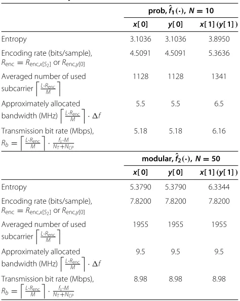
Some system parameters of the proposed VTR-MB-OFDM system are listed in Table 2, where x[ 0] means S2 = 0 andfˆ(aT, 0)are encoded,y[ 0] meansS1 = 0 and
Table 2 System parameters of the proposed VTR-MB-OFDM system
prob,ˆf1(·),N=10
x[ 0] y[ 0] x[ 1](y[ 1])
Entropy 3.1036 3.1036 3.8950
Encoding rate (bits/sample),
Renc=Renc,x[S2]orRenc,y[0]
4.5091 4.5091 5.3636
Averaged number of used subcarrier(L·Renc
M
) 1128 1128 1341
Approximately allocated bandwidth (MHz)(L·Renc
M
)
·f
5.5 5.5 6.5
Transmission bit rate (Mbps),
Rb=
(
L·Renc
M
)
· fs·M NT+NCP
5.18 5.18 6.16
modular,ˆf2(·),N=50
x[ 0] y[ 0] x[ 1](y[ 1])
Entropy 5.3790 5.3790 6.3344
Encoding rate (bits/sample),
Renc=Renc,x[S2]orRenc,y[0]
7.8200 7.8200 7.8200
Averaged number of used subcarrier(L·Renc
M
) 1955 1955 1955
Approximately allocated bandwidth (MHz)(L·Renc
M
)
·f
9.5 9.5 9.5
Transmission bit rate (Mbps),
Rb=
(
L·Renc
M
)
· fs·M NT+NCP
8.98 8.98 8.98
ˆ
f(0,bT) are encoded,x[ 1] means S2 = 1 andfˆ(aT,bT) are encoded, and the system parameters ofx[ 1] are equal to the system parameters ofy[ 1]. In Table 2, the encoding rates are greater than the entropies. It is important that the transmission of the proposed VTR-MB-OFDM sys-tem is also admissible. In addition, the used subcarriers, the occupied bandwidths, and the transmission rates are estimated usingL·Rencinstead ofXandYfor both map-ping functions, because the entire packet transmission is a stochastic process which meansXandY are not con-stants, andRenc provides the averaged codeword length of possible output data samples. Furthermore, two impor-tant issues need to be addressed in Table 2. First, if the mapping function at both encoders is fˆ1(·), the system parameters ofx[ 0] are equal to the system parameters of y[ 0]. This is because{ai}and{bi}have the same pdf. Sec-ond, the system parameters ofx[ 0],y[ 0], andx[ 1] are the same using the mapping functionfˆ2(·), becausefˆ2(·)maps the input pair(ai,S2·bi)or(S1·ai,bi)to a single value at both encoders. For the mapping functionfˆ1(·), 4 different switch configurations in [S1S2] generate different trans-mission rates to transmit correlated sequences {ai} and
The performance of the proposed VTR-MB-OFDM sys-tem over the noiseless channel is shown in Figure 5. We evaluate the effects of 16 different switch configurations to the system performance using two different mapping functions,fˆ1(·)andfˆ2(·), at both encoders in Figure 5a,b, respectively. If the mapping functionfˆ1(·)is chosen, the SER reaches to 0.5 or 1 when
⎧ ⎪ ⎨ ⎪ ⎩
[S1S2]=[ 0 0] [S3S4]=[ 1 1] [S3S4]=[S1S2] .
(49)
Moreover, if the mapping functionˆf2(·)is chosen, the SER reaches to 0.5 or 1 when
[S1S2]=[ 1 1] (50)
or
⎧ ⎪ ⎨ ⎪ ⎩
[S1S2]=[ 0 0] [S3S4]=[ 1 1] [S3S4]=[S1S2] .
(51)
For [S1 S2]=[ 0 0], the input pairs are mapped inde-pendently. Thus, decoders can decode the estimated bit stream correctly with or without the side information. In
(a)
(b)
Figure 5The performance of the proposed VTR-MB-OFDM system in the noiseless channel using two different mapping functions. (a)ˆf1(·)with switch configurations [S1S2S3S4]=[x x x x].(b)fˆ2(·)with switch configurations [S1S2S3S4]=[x x x x]. ’x’ means ’0’ or ’1’. Therefore,
(a)
(b)
(c)
(d)
(e)
(f)
(g)
(h)
Figure 6The performance of the proposed VTR-MB-OFDM communications system in the AWGN channel using two different mapping functions.(a)ˆf1(·)with switch configurations [S1S2S3S4]=[ 0 0x x].(b)ˆf1(·)with switch configurations [S1S2S3S4]=[ 0 1x x].(c)ˆf1(·)with
switch configurations [S1S2S3S4]=[ 1 0x x].(d)ˆf1(·)with switch configurations [S1S2S3S4]=[ 1 1x x].(e)ˆf2(·)with switch configurations
[S1S2S3S4]=[ 0 0x x].(f)ˆf2(·)with switch configurations [S1S2S3S4]=[ 0 1x x].(g)fˆ2(·)with switch configurations [S1S2S3S4]=[ 1 0x x].(h) ˆ
f2(·)with switch configurations [S1S2S3S4]=[ 1 1x x]. ’x’ means ’0’ or ’1’. From Figure 6a–d, effects caused by 16 different switch configurations to
the system performance using the mapping functionˆf1(·)are evaluated, and then we also evaluate the effects caused by 16 different switch
the case of [S3S4]=[S1S2] for both mapping functions, decoders decode the estimated bit stream in a way differ-ent from the way that encoders generate these encoded bit stream. In addition, for the mapping functionfˆ2(·), the reason we have the highest SER when [S1S2]=[ 1 1] is that the decoder can not map a single value back to the origi-nal input pair{ˆai,bˆi}with or without the help of the side information.
We demonstrate the performance of the proposed VTR-MB-OFDM system over the AWGN channel using two different mapping functions in Figure 6. The system per-formance using the mapping function fˆ1(·) is demon-strated in Figure 6a–d, and then the system performance using the mapping functionfˆ2(·) is also demonstrated in Figure 6e–h. From Figure 6, the system performance over the noiseless channel is the same as the system perfor-mance over the noisy channel when SNR is greater than 19 dB. Compared with the traditional uncoded OFDM system, the proposed VTR-MB-OFDM system has at least 1 to 4 dB gain in SNR to achieve the same SER. In addi-tion, the proposed VTR-MB-OFDM system achieves zero SER for some switch configurations when SNR is greater than 19 dB.
5 Conclusion
In this article, two variable transmission rate OFDM sys-tems using network coding schemes are proposed, and the performance of these two proposed systems is evaluated. For the proposed VTR-SISO-OFDM system, the trans-mission rate is adjusted by selecting the bit stream from the output at different stages with different mapping func-tions in the encoder; however, how an appropriate map-ping function is chosen is important for the system per-formance. In addition, the cardinalities of the side infor-mation also affect the system performance. The larger the codebook size, the less gain in SNR to achieve the same performance as the uncoded communications sys-tem. Thus, a trade-off between higher transmission rate and better system performance is necessary. As for the proposed VTR-MB-OFDM system, correlated sources are simultaneously transmitted using different transmission rates. Different switch configurations generate different transmission rates at the transmitter and different system performance at the receiver. Compared with the tradi-tional uncoded OFDM system, simulation results show the proposed VTR-SISO-OFDM system has at least 1 to 3 dB gain in SNR to achieve the same SER, and the pro-posed VTR-MB-OFDM system has at least 1 to 4 dB gain in SNR to achieve the same SER. In addition, for some conditions, zero SER is achievable for both proposed sys-tems when SNR is greater than 19 dB. Moreover, the rate factors of these two proposed system vary from 0.55 to 0.96.
Competing interests
The authors declare that they have no competing interests.
Acknowledgements
The authors would like to thank Emeritus Professor John C. Kieffer and anonymous reviewers for their valuable advice which substantially improved this article.
Received: 20 April 2012 Accepted: 17 January 2013 Published: 1 February 2013
References
1. J Proakis,Digital Communications. (McGraw Hill, New York, NY, 2000) 2. G Stuber,Principle of mobile communication. (Kluwer Academic Publishers,
Norwell, MA, 2000)
3. Q Zhao, Network source coding: theory and code design for broadcast and multiple access network. Ph.D. thesis, California Institute of Technology (2003)
4. S Tung, Multiterminal source coding. Ph.D. thesis, Cornell University (1978) 5. C Shannon, A mathematical theory of communication. Bell Systs. Tech. J.
27, 379-423, 623-656 (1948)
6. M Effros, Network source coding: a perspective. IEEE Inf. Theory Soc. Newslett.57(4), 15-23 (2007)
7. D Slepian, J Wolf, Noiseless coding of correlated information sources. IEEE Trans. Inf. Theory.IT-19(4), 471-480 (1973)
8. H Yamamoto, Wyner-ziv theory for a general function of the correlated sources. IEEE Trans. Inf. Theory.IT-28(5), 1788-1791 (1982)
9. H Feng, M Effros, S Savari, inProceedings of the Allerton Conference on Communication, Control, and Computing. Functional source coding for networks with receiver side information, (Monticello, IL, 2004), pp. 1419-1427
10. A Orlitsky, J Roche, Coding for computing. IEEE Trans. Inf. Theory. 47(3), 903-917 (2001)
11. R Ahlswedw, N Cai, SY Li, R Yeung, Network information flow. IEEE Trans. Inf. Theory.IT-46(4), 1204-1216 (2000)
12. T Ho, M M´edard, R Koetter, D Karger, M Effros, J Shi, B Leong, A random linear network coding approach to multicast. IEEE Trans. Inf. Theory. 52(10), 4413-4430 (2006)
13. R Nee, R Prasad,OFDM Wireless Multimedia Communication. (Artech House, Norwood, MA, 2000)
14. IEEE 802.15 Task Group, Multi-band OFDM Physical Layer Proposal for IEEE 802.15 Task Group 3a (2003)
15. J Balakrishnan, A Batra, A Dabak, inProceedings of IEEE Conference Ultra Wideband System Technology. A multi-band OFDM system for UWB communication, (Virginia, USA, 2003), pp. 354-358
16. R Zhang, L Hanzo, Multiple-source cooperation: from code-division multiplexing to variable-rate network coding. IEEE Trans. Veh. Technol. 60(3), 1005-1015 (2011)
17. A Wyner, J Ziv, The rate-distortion function for source coding with side information at the decoder. IEEE Trans. Inf. Theory.IT-22(1), 1-10 (1976) 18. T Berger,Multiterminal Source Coding. (Springer-verlag, New York, 1978) 19. J Kieffer, A method for proving multiterminal source coding theorems.
IEEE Trans. Inf. Theory.IT-27(5), 565-570 (1981)
doi:10.1186/1687-6180-2013-12
Cite this article as:Kung and Parhi:Performance evaluation of variable


![Figure 5 The performance of the proposed VTR-MB-OFDM system in the noiseless channel using two different mapping functions.(a) fˆ1(·) with switch configurations [ S1 S2 S3 S4] =[ x x x x]](https://thumb-us.123doks.com/thumbv2/123dok_us/1136983.1142607/14.595.59.536.190.691/figure-performance-proposed-noiseless-channel-dierent-functions-congurations.webp)

