University of Windsor University of Windsor
Scholarship at UWindsor
Scholarship at UWindsor
Electronic Theses and Dissertations Theses, Dissertations, and Major Papers
11-7-2015
Architecture for Extracting Data from Vehicular Sensors
Architecture for Extracting Data from Vehicular Sensors
Gaurav Sood
University of Windsor
Follow this and additional works at: https://scholar.uwindsor.ca/etd
Recommended Citation Recommended Citation
Sood, Gaurav, "Architecture for Extracting Data from Vehicular Sensors" (2015). Electronic Theses and Dissertations. 5514.
Architecture for Extracting Data from Vehicular Sensors
By
Gaurav Sood
A Thesis
Submitted to the Faculty of Graduate Studies through the School of Computer Science in Partial Fulfillment of the Requirements for
the Degree of Master of Science at the University of Windsor
Windsor, Ontario, Canada
2015
Architecture for Extracting Data from Vehicular Sensors
by
Gaurav Sood
APPROVED BY:
______________________________________________ Dr. Huapeng Wu
Department of Electrical and Computer Engineering
______________________________________________ Dr. Jianguo Lu
Department of Computer Science
______________________________________________ Dr. Ataul Bari, Co-advisor
Department of Electrical and Computer Engineering
DECLARATION OF ORIGINALITY
I hereby certify that I am the sole author of this thesis and that no part of this thesis has been published or submitted for publication.
I certify that, to the best of my knowledge, my thesis does not infringe upon anyone’s copyright nor violate any proprietary rights and that any ideas, techniques, quotations, or any other material from the work of other people included in my thesis, published or otherwise, are fully acknowledged in accordance with the standard referencing practices. Furthermore, to the extent that I have included copyrighted material that surpasses the bounds of fair dealing within the meaning of the Canada Copyright Act, I certify that I have obtained a written permission from the copyright owner(s) to include such material(s) in my thesis and have included copies of such copyright clearances to my appendix.
ABSTRACT
In this thesis we investigate an alternate source of vehicular information for
collision avoidance systems and driver assistance applications, which is more
accurate, reliable in all conditions and has minimum time lag. We have designed
and developed an architecture, which enables us to read, analyze, decode and store
the real-time vehicular data from the vehicle’s electric sensors. We have designed
two algorithms for decoding the raw data read from the vehicle’s Controller Area
Network (CAN) [7] bus, to which various electric components of the vehicle are
connected to communicate the real-time data.
We have shown that the vehicular speed which is a very important
parameter in the calculation of ‘Time to Collision (TTC)’ by collision avoidance
algorithms [22] is more accurate, reliable and has higher polling rate, when
calculated from the vehicle’s CAN bus as compare to the other source of
information i.e. GPS [6].
DEDICATION
To my father whose shower of blessings remains with me and always motivates
ACKNOWLEDGEMENTS
My ultimate gratitude goes to my supervisor Dr. Arunita Jaekel, for
providing me the opportunity to work in an exciting and challenging field of
research. Her constant support, guidance and belief in me have played a major role
towards successful completion of my thesis. Her suggestion to work as a Research
Intern at Arada Systems, Windsor proved decisive in defining my research goals
and in identifying the ways to achieve them.
I would like to acknowledge Dr. Ataul Bari, Dr. Huapeng Wu and Dr. Jianguo Lu
whose suggestions and recommendations greatly improved the quality of this
work. I would also like to thank Mr. Nazeer Shaik for his suggestions and
arrangements to complete the testing in Michigan, USA. I am thankful to my
friend and colleague Jordan Willis for his continuous support and help in this work
and learning new things. And I want to thank my best friends Arshdeep Singh
Sidhu and Manpreet Kaler for always standing besides me and motivating me in
tough times.
Finally, to three wonderful women in my life, my caring mother, my loving
and supportive wife and my sweet sister: my deepest gratitude. Their
encouragement and support are much appreciated during entire phase of my
TABLE OF CONTENTS
DECLARATION OF ORIGINALITY ... iii
ABSTRACT ... iv
DEDICATION ...v
ACKNOWLEDGEMENTS ... vi
LIST OF TABLES ...x
LIST OF FIGURES ... xi
LIST OF APPENDICES ... xiii
LIST OF ABBREVIATIONS ... xiv
CHAPTER-1 INTRODUCTION ...1
1.1 Overview ... 1
1.2 Motivation ... 2
1.3 Problem Statement ... 3
1.4 Solution Outline ... 4
1.5 Thesis Organization ... 6
CHAPTER-2 REVIEW OF LITERATURE ...7
2.1 Introduction to Intelligent Transportation Systems ... 7
2.2 Vehicle-to-Infrastructure (V2I) and Vehicle-to-Vehicle (V2V) Communication ... 9
2.2.1 Dedicated Short Range Communications Protocol ... 11
2.2.2 V2V Devices ... 13
2.2.2.1 Original Equipment Manufacturer (OEMs) ... 14
2.2.2.2 Aftermarket Devices ... 14
2.2.2.3 Infrastructure Based Devices ... 16
2.2.3 V2V Safety Applications ... 16
2.3 Controller Area Network (CAN) Bus ... 17
2.3.2 CAN Bus Data Extraction ... 22
2.4 Collision Avoidance Systems ... 24
2.4.1 Global Positioning System Data Based Systems ... 24
2.4.2 Other Novel Techniques ... 26
CHAPTER-3 ...30
THESIS OBJECTIVE AND RESEARCH METHODOLOGY ...30
3.1 Introduction ... 30
3.2 Synopsis of Problems and Limitations ... 31
3.3 Statement of Objectives ... 32
3.4 Research Methodology ... 33
3.4.1 Architecture of the System ... 35
3.4.2 Software Architecture ... 39
3.4.3 Software UML Class Structure ... 45
CHAPTER-4 RESULTS AND ANALYSIS ...52
4.1 Test Setup ... 52
4.2 Comparison of CAN Speed and GPS Speed ... 53
4.2.1 Test Results at a Parking Lot ... 53
4.3.2 Test Results at a City Road ... 55
4.3.3 Test Results on a Highway ... 57
4.3.4 Test Results at Downtown ... 58
4.3 Other Vehicular Sensor’s Data ... 59
CHAPTER-5 CONCLUSION & FUTURE WORK ...61
5.1 Conclusion ... 61
5.2 Future Work ... 62
REFERENCES ...63
LIST OF TABLES
Table I: Typical DSRC data traffic requirements………...13
LIST OF FIGURES
Figure 2.1: National ITS Architectures of America………..8
Figure 2.2: Framework for integrated transportation system………8
Figure 2.3: V2I controlled traffic situations………..9
Figure 2.4: Visual Representation of V2V Communication………...11
Figure 2.5: Examples of Crash Scenarios and Vehicle-to-Vehicle Applications…17 Figure 2.6: Structure of CAN Network………...19
Figure 2.7: Structure of CAN frame………21
Figure 2.8: USB CAN smart card………...23
Figure 2.9: CAN frames display window………23
Figure 2.10: Graphical illustration of two vehicles A and B and their collision path………..25
Figure 2.11: Graphical illustration of rear-end collision……….26
Figure 2.12: Path prediction using DS reasoning system………28
Figure 3.1: System Architecture Flow Diagram……….34
Figure 3.2: System Architecture……….35
Figure 3.3: CAN to OBD-II Cable………..36
Figure 3.4: OBU (LocoMate), Arada Systems, Windsor………37
Figure 3.5: GPS Antenna………38
Figure 3.6: CAN-Ethernet Gateway Flow Diagram………39
Figure 3.7: Screenshot of CAN DBC file………...40
Figure 3.8: Software Architecture Flow Diagram………...42
Figure 3.10: Screenshot of Sensor’s Decoded Values………....44
Figure 3.11: CAN-Ethernet Application Software UML Class Diagram………...46
Figure 4.1: Comparison CAN Speed and GPS Speed at a Parking Lot…………..54
Figure 4.2: Comparison of CAN Speed and GPS Error at a Parking Lot………...55
Figure 4.3: Comparison CAN Speed and GPS Speed at a City Road……….56
Figure 4.4: Comparison of CAN Speed and GPS Error at a City Road…………..56
Figure 4.5: Comparison CAN Speed and GPS Speed on a Highway……….57
Figure 4.6: Comparison of CAN Speed and GPS Error on a Highway…………..58
Figure 4.7: Comparison CAN Speed and GPS Speed at Downtown………..58
Figure 4.8: Comparison of CAN Speed and GPS Error at Downtown…………...59
LIST OF APPENDICES
Appendix A: Big Endian Algorithm………...69
LIST OF ABBREVIATIONS
1. ABS Anti-lock Braking System
2. ACK Acknowledge
3. ARP Address Resolution Protocol
4. ASC Automatic Stability Control
5. AT Auto Tracker
6. BSM Basic Safety Message
7. CA Constant Acceleration
8. CAN Controller Area Network
9. CRC Cyclic Redundant Check
10.CTR Constant Turn Rate
11.CTRA Constant Turn Rate and Acceleration
12.CV Constant Velocity
13.DHCP Dynamic Host Configuration Protocol
14.DLC Data Length Code
15.DS Dempster-Shafer
16.DSRC Dedicated Short Range Communications
17.ECU Engine Control Unit
18.EEBL Emergency Electronic Brake Light
23.FCC Federal Communications Commission
24.FIFO First In First Out
25.GPS Global Positioning System
26.ICMP Internet Control Message Protocol
27.IDE Identifier Extension
28.IFS Intermission Frame Space
29.IP Internet Protocol
30.IPT Inverse Perspective Transform
31.ISO International Organization for Standardization
32.ITS Intelligent Transportation System
33.LAN Local Area Network
34.LIDAR Light Detection and Ranging
35.LRR Long Range Radar
36.NHTSA National Highway Traffic Safety Administration
37.OBD On-board Diagnostics
38.OBU On Board Unit
39.OEM Original Equipment Manufacturer
40.RSE Road Side Equipment
41.RTR Remote Transmission Request
42.SoF Start of Frame
43.SpaT Signal Phasing and Timing
44.TCP Transmission Control Protocol
46.UDP User Datagram Protocol
47.UKF Unscented Kalman Filter
48.USB Universal Serial Bus
49.V2I Vehicle to Infrastructure
50.V2V Vehicle to Vehicle
CHAPTER-1
INTRODUCTION
1.1Overview
Vehicular safety technology has developed rapidly in the last two decades.
Modern vehicles can protect occupants much better in the event of a crash, due to the
advanced structural design techniques complemented by more stringent road standards,
and some mandatory standard crash avoidance technologies. All these advances have
made motor vehicles safer than they have ever been. However, there are still a significant
number of annual crashes that could potentially be eliminated through expanded use of
more advanced crash avoidance technologies. It has been estimated by National Highway
Traffic Safety Administration (NHTSA) [5] that there are more than five million annual
vehicle crashes with property damage, injuries and fatalities. So, if deployment of
technology can help to avoid these crashes, the damage due to crashes never occurs.
Some of the most advanced collision avoidance technologies present on the
vehicles today include cameras, on-board sensors and radar applications. These
technologies may warn the drivers of impending collision thus helping them to take
corrective actions. While these current technologies are highly beneficial, the Vehicle to
Vehicle (V2V) communications [4] represent an additional step in helping to warn
drivers of the impending collision threats. V2V communications use on-board dedicated
short-range radio communication (DSRC) [8] [9] devices to transmit messages about a
vehicle’s location information, speed, heading, brake status, and other information to
and line of sight, which can be more than twice of that of the current systems. This longer
detection distance and ability to see around corners or through other vehicles helps
V2V-equipped vehicles perceive some threats sooner than sensors, cameras, or radar can, and
warn their drivers accordingly. V2V can be combined with other driver assistance
applications to act as a complete system that cover the scenarios which are not covered
by V2V alone, such as lane or road departure warning. A complete system could also
augment system accuracy, potentially leading to improved warning timing and reducing
the number of false warnings [5].
1.2Motivation
According to the statistics published by NHTSA, a total number of 99,176
fatalities was reported in the United States, due to the vehicle traffic crashes during the
period of 2012-2014, with the year 2012 having the maximum number of fatalities at
33,782 [47]. According to another data record published by NHTSA, more than 10
million motor vehicle accidents were reported every year in the US and economic cost of
traffic crashes up till year 2010, was estimated to USD 242 billion [48] [49]. According
to the ‘2013 National Statistics’ given by NHTSA, total number of 30,057 fatalities and
1,591,000 injuries was reported due to road accidents in the US. These vehicle traffic
crashes had also resulted in a property damage of USD 4,066,000 [49]. According to the
‘Canadian Motor Vehicle Traffic Statistics 2012’, total number of 123,963 vehicular
Researchers and technology experts from around the world are working to
develop new ways to minimize the losses occurring due to traffic collisions. Various
technologies such as Airbag System, and Anti-lock Braking System have been
incorporated and mandated by vehicle manufacturers and traffic regulatory bodies over
the period of time, which have proved highly beneficial to reduce the number of vehicle
crashes and related losses. To add more sophistication, a lot of work is being carried on
the improvement and development of collision avoidance algorithms. These algorithms
incorporated with V2V communications are considered as very useful technologies to be
incorporated in the next generation of vehicles. The accuracy of these algorithms depends
on the availability of real time, reliable and accurate source of input parameters e.g.
positioning information, speed and brake status. In this thesis, we focus on techniques
for accurate and timely collection of various vehicular parameters (e.g. speed, engine
rpm, brake status etc.), which can aid in the development of better collision avoidance
algorithms and driver assistance applications.
1.3Problem Statement
Currently, most of the collision avoidance algorithms rely on GPS [6] for the
real-time situation parameters of the vehicles. For example, the collision warning system
presented in [22] and [23], calculates ‘Time to Collision (TTC)’ between two vehicles
using GPS information (e.g. longitude, latitude, speed, heading, altitude and acceleration)
exchanged using V2V communications. Another system presented in [32], uses vehicular
ad-hoc network (VANET) router, a GPS system, inertial sensors for measuring the speed,
vehicle. Since these systems work in real time conditions, so the input parameters need to
be accurate, reliable in all conditions and have minimum time lag.
The data obtained from GPS signals is significantly less accurate during bad
weather conditions, in urban downtown areas and tunnels, either because of the signal
distortion, or no GPS signals are received in these conditions. Also, the polling rate of
current GPS receivers is low with intervals up to 200 milliseconds, which may not be
adequate for real-time systems like collision avoidance systems. Similarly, a system
based on camera would have high maintenance costs and also may give less accurate
warnings during bad weather conditions and at night. Furthermore, current source of
information like GPS provides access to only a limited number of vehicular parameters
like speed and acceleration. This has led to the development of collision avoidance
algorithms with limited scope and accuracy. All these factors have resulted in inaccurate
calculation of TTC [22], which resulted in wrong or no warnings of the impending
collisions. So, there is a need to improve the source of vehicular information which
should be more accurate, reliable in all conditions and has higher polling rate. Also, a
number of additional important vehicular parameters like steering angle, brake status,
yaw rate, turn indicator status etc. should be extracted, which could lead to the
development of more sophisticated collision avoidance algorithms.
from GPS. Extracting data directly from vehicle’s sensors would result in more accurate
and real-time data with very less time lag. In modern vehicles, all the electric devices of
the vehicle are connected to each other by a bus network called Controller Area Network
(CAN) [7]. The vehicle’s electric devices communicate with each other through CAN
protocol, which helps the devices to access the most recent information from various
components. Each message has a unique CAN ID present in the header which helps the
devices to recognize different messages.
The CAN bus can be accessed using the OBD-II port [19] present in the vehicle.
We have designed and developed a software application named CAN-Ethernet which
uses an Ethernet dongle to connect to the OBD-II port of the vehicle. The CAN Ethernet
software reads, analyzes, decodes and stores the CAN data read from the CAN bus in
real-time. The software runs as a server application to act as a source of CAN data and
enables up to five different client connections at the same time. Can-Ethernet software
takes, as input, a DBC file [44], which defines the CAN IDs and other information
helpful in decoding the CAN messages. We have designed two algorithms, one for little
endian [51] and other for big endian byte order [51], that decode the CAN messages read
from the CAN Bus. After decoding, the information is populated in data structures that
store the real time value of each sensor parameter and also written to the log files. We are
able to extract a number of vehicular parameters like speed, engine rpm, brake status,
steering angle, yaw rate, accelerator pedal position, headlight status, wiper status,
ambient temperature and ambient pressure. All these parameters information can prove
very useful in developing and improving collision avoidance systems and driver
1.5Thesis Organization
The remainder of our thesis is organized as follows. Chapter 2 gives the brief
description about the Intelligent Transportation Systems (ITS) including V2V and V2I
technologies. A brief introduction about CAN Bus protocol and some existing collision
avoidance technologies is also provided in this chapter. Chapter 3 presents our proposed
CAN-Ethernet application software architecture. Chapter 4 discusses and analyzes our
test results. Chapter 5 concludes our work and identifies some possible directions for the
future work.
CHAPTER-2
REVIEW OF LITERATURE
2.1 Introduction to Intelligent Transportation Systems
“Intelligent transportation systems (ITS) are advanced applications which,
without embodying intelligence as such, aim to provide innovative services relating to
different modes of transport and traffic management and enable various users to be better
informed and make safer, more coordinated, and 'smarter' use of transport networks” [1].
In general, ITS is an application of advanced technologies which includes computers,
sensors, communications, and various electronic devices to make commutation safer,
quicker, energy efficient and environment friendly.
The growing congestion and safety problems in transportation networks along
with infrastructural, environmental and land constraints have resulted in the demand of
adequate and efficient use of the existing resources. The application of ITS is critical in
solving such problems. Various sophisticated applications are already in use and are
being developed to improve transportation around the world. For example, computers and
communication systems are being integrated to provide link between vehicles, travelers
and infrastructures to address the modern problems of traffic collisions and congestion to
save precious lives and energy.
National ITS architectures for several countries were designed and planned,
including the research area and transportation service. The American national ITS
Figure 2.1: National ITS Architectures of America [2] [3]
A basic framework for developing an integrated transportation systems provided
by ITS architecture is shown in Figure 2.2.
2.2 Vehicle-to-Infrastructure (V2I) and Vehicle-to-Vehicle (V2V)
Communication
In V2I, the infrastructure plays a coordination role by gathering situation
awareness information on traffic and road conditions and then suggesting or imposing
certain behavior conditions on the vehicles. In other scenarios, vital information about
traffic signals or pedestrian movement is transmitted to the vehicles thereby alerting the
drivers to react in a timely fashion. In a more sophisticated scenario, the velocities and
accelerations of vehicles and inter-vehicle distances would be suggested by the
infrastructure on the basis of traffic conditions, with the goal of optimizing overall
emissions, fuel consumption, and traffic velocities. The information can be broadcast to
the vehicles or can be relayed to other vehicles by using multi-hop networking of the
V2V.
The figure 2.3 shows two different traffic situations [4]. In the left panel, traffic
density is low and the central infrastructure based controller acts to improve fuel
efficiency and reduce emissions of individual vehicles, smoothing accelerations and
decelerations; in the right panel, due to greater congestion, the infrastructure control is
primarily concerned with depleting queues at intersections with an eye toward global fuel
economy and emissions reduction.
V2V is a decentralized system as compared to V2I, which aims at organizing the
interaction among vehicles and possibly developing collaborations among them [4]. In
this system, vehicles periodically exchange information to make decisions for the future
behavioral actions. In a general V2V scenario, when two or more vehicles come within a
communication range, they connect automatically and make an ad-hoc network to share
their position, direction, speed, acceleration, braking and various other parameters’ data.
The vehicles get their own parameters’ data from various sources like Global Positioning
Data (GPS) [6], Controller Area Network (CAN) [7], and Road Side Equipments (RSEs)
[5]. The devices placed on the vehicles to receive, process and transmit the data are
called On-Board Units (OBUs) [5]. These OBUs act as routers which enable the
multi-hop transmission of the data to more distant vehicles and road side stations.
Figure 2.4: Visual Representation of V2V Communication [5]
The wireless communication is based on IEEE 802.11a, also known as Dedicated
Short Range Communications (DSRC). A frequency spectrum of 5.9-GHz range has been
allocated to support the development of safety applications based on V2I and V2V
communication systems [5] [8].
2.2.1 Dedicated Short Range Communications Protocol
Dedicated Short-Range Communications (DSRC) is 75 MHz of spectrum at 5.9
GHz allocated by the Federal Communications Commission (FCC) to “increase traveler
safety, reduce fuel consumption and pollution, and continue to advance the nation’s
economy [8].” It is developed to dedicatedly support V2V and V2I communications
communications like collision warnings, as well as other valuable ITS applications such
as Electronic Toll Collection (ETC), digital map update, etc. The versatility of DSRC
greatly enhances the likelihood of its deployment by various industries and adaptation by
the consumers.
The 2004 FCC ruling [9] specifies DSRC will have six service channels and one
control channel. The control channel is to be regularly monitored by all vehicles. Safety
messages, whether originated by vehicles or roadside transmitters, are to have priority
over non-public safety communications. Therefore all safety messages are to be sent in
the control channel. In the meantime, a licensed roadside unit could use the control
channel to inform approaching vehicles of its services (often non-safety applications) and
conduct the actual application in one of the service channels. For example, a roadside unit
could announce a local digital map update in the control channel and transfer this data to
interested vehicles in a service channel.
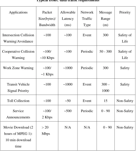
Table I illustrates the sort of DSRC data traffic characteristics being used in the
standards deliberations [10] [11] [12]. The FCC has recognized safety messages and
“safety of life” messages. Safety of life is to have the highest priority. The non-safety
data transfers have the lowest priority. The non-safety communications happen for file
transfers (e.g., infotainment) or transactions (e.g. toll collection). Transactions may
Table I
Typical DSRC data traffic requirements
Applications Packet
Size(bytes)/ Bandwidth Allowable Latency (ms) Network Traffic Type Message Range (m) Priority Intersection Collision Warning/Avoidance
~100 ~100 Event 300 Safety of
Life
Cooperative Collision
Warning
~100/
~10 Kbps
~100 Periodic 50 - 300 Safety of
Life
Work Zone Warning ~100/
~1 Kbps
~1000 Periodic 300 Safety
Transit Vehicle
Signal Priority
~100 ~1000 Event 300 –
1000
Safety
Toll Collection ~100 ~50 Event 15 Non-Safety
Service
Announcements
~100/
2 Kbps
~500 Periodic 0 - 90 Non-Safety
Movie Download (2
hours of MPEG 1):
10 min download
time
> 20
Mbps
N/A N/A 0 - 90 Non-Safety
2.2.2 V2V Devices
Various types of V2V devices are available which are either placed inside the
All these types support different types of V2V and V2I safety applications. These devices
can be categorized as follows.
2.2.2.1 Original Equipment Manufacturer (OEMs)
An OEM device is an electronic device integrated into a vehicle during vehicle
manufacturing. A V2V system is integrated into these devices which is connected to the
proprietary CAN busses [7] and can provide highly accurate information running in these
busses. This vehicle information along with the data collected from the GPS receivers is
used to generate Basic Safety Messages (BSMs) [5]. The integrated system both
broadcasts and receives BSMs and also has a processor that can process the contents of
the received messages to provide advisories and warnings to the driver of the vehicle in
which it is installed. Because the device is fully integrated into the vehicle at the time of
manufacture, vehicles with Integrated Safety Systems could potentially provide haptic
warnings to alert the driver (such as tightening the seat belt or vibrating the driver’s seat)
in addition to audio and visual warnings provided by the aftermarket safety devices. The
equipments required for an integrated OEM V2V system would consist of a general
purpose processor, associated memory, a radio transmitter and transceiver, antennas,
interfaces to the vehicle’s CAN bus, and a GPS receiver. These types of integrated
devices can be collaborated with other vehicle-resident collision avoidance systems to
exploit the functionality of both types of systems.
the vehicle after its original assembly. A V2V communication aftermarket device
generally provides warnings and/or advisories to the driver similar to those provided by
OEM installed V2V devices. These devices, however, may not be as fully integrated into
the vehicle as an OEM device, and the level of connection to the vehicle can vary based
on the type of aftermarket device itself. For example, an independent V2V aftermarket
safety device could only connect to a power source, and otherwise would operate
independently from the systems in the vehicle. Aftermarket V2V devices can be added to
a vehicle at a vehicle dealership, as well as by authorized dealers or installers of
automotive equipment. Some aftermarket V2V devices (e.g., cell phones with apps) are
portable and can be standalone units carried by the operator or the passenger.
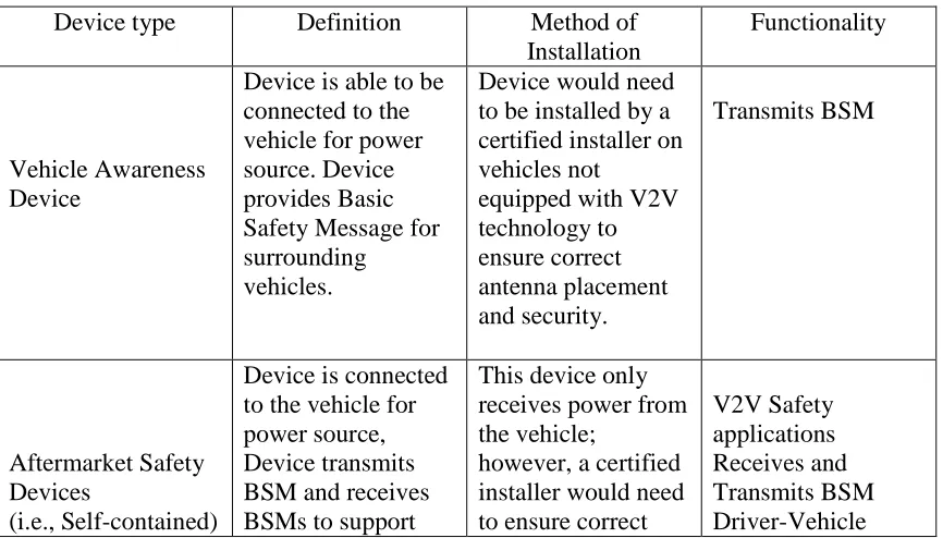
Table II [5] shows the details of all types of aftermarket devices that are employed
in the vehicles.
Table II
Aftermarket Safety Device Types
Device type Definition Method of
Installation
Functionality
Vehicle Awareness Device
Device is able to be connected to the vehicle for power source. Device provides Basic Safety Message for surrounding
vehicles.
Device would need to be installed by a certified installer on vehicles not
equipped with V2V technology to ensure correct antenna placement and security. Transmits BSM Aftermarket Safety Devices (i.e., Self-contained)
Device is connected to the vehicle for power source, Device transmits BSM and receives BSMs to support
This device only receives power from the vehicle;
however, a certified installer would need to ensure correct
safety applications for the driver of the vehicle in which it is installed. antenna placement and security. Interface Retrofit Safety Devices
Device is connected to the vehicle’s data bus that provides BSM and safety applications for the driver of the vehicle in which it is installed.
This device needs to be connected to the vehicle’s data bus, therefore would require an installer that can access this for the particular make of vehicle. Also, a certified installer would need to ensure correct antenna placement and security. V2V Safety applications Receives and Transmits BSM Driver Vehicle Interface
Integration into the vehicle data bus
2.2.2.3 Infrastructure Based Devices
Infrastructure based devices can be defined as devices that are co-located along
with road side equipments that allow vehicles to receive information from the
infrastructure. The road side equipments can be road signs, traffic signals etc. General
applications that run on these devices are related to signal phasing and timing (SPaT),
curve and curve speed warnings, traffic advisories etc.
2.2.3 V2V Safety Applications
V2V technology communicates via DSRC (radio signals) which offer 360 degree
addition, V2V systems are not affected by weather conditions, light, or conditions of road
as in the case of other systems dependent on cameras or Light Detection and Ranging
(LIDAR) [13].
In figure 2.5 various safety applications and scenarios they can address are shown.
Figure 2.5: Examples of Crash Scenarios and Vehicle-to-Vehicle Applications [5]
2.3 Controller Area Network (CAN) Bus
There are many electronic devices in today’s in-vehicle e.g. anti-lock braking
system (ABS) and automatic stability control (ASC), and the number of these devices
incorporated is increasing gradually. These devices need to communicate with each other.
As a point-to-point communication would increase the wiring that would lead to increase
Controller Area Network or CAN bus designed and developed by Robert Bosch GmBh
[7] is international standardized and defined in the ISO 11898-1 [16]. As a network
specification for electric control system of vehicle, CAN has the capacity of real time
control. The efficient use of these electronic devices through bus network has helped to
reduce the oil consumption and air pollution, improve the ability, safety and comfort of
the vehicle and make drive easy. Some of the electronic devices that are used are engine
timer, auto tracker (AT) and accelerator paddle controller, anti-lock braking system
(ABS), automatic stability control (ASC), intelligent air bag, air conditioning and sound
device [14].
The Controller Area Network (CAN) is a serial communications protocol which
efficiently supports distributed real-time control with a very high level of security [7].
CAN is one of the most popular in-vehicle networks. It simplifies the cable in vehicle, so
the weight of the vehicle is reduced and easy to maintain and repair [15].
In figure 2.6 a general structure of the CAN network is shown. Many electronic
devices are connected to CAN network and communicate with each other. The
microcontroller in each electronic device communicate to CAN controller and CAN
controller connects CAN bus via CAN driver. CAN network is composed of 2 lines and
Figure 2.6: Structure of CAN Network [15]
The various advantages of CAN protocol are discussed as follows [14] [17] [18].
• Latency Time: This is defined as the time a transmitting node is ready to send
information up until the time the transmission has been completed. CAN has the
short latency time that is essential in the real-time control applications.
• Electromagnetic Compatibility (EMC) and Electromagnetic Interference (EMI):
The performance is not affected by radiated emissions and susceptibility.
• Error Handling and Fault recovery: Less than one undetected error rate in the
lifetime of the vehicle is considered reasonable. The ability to handle and recover
quickly from faults was considered as an important factor for the CAN protocol.
• Data Consistency: Ensure the consistency of data across the network, particularly
when sharing sensor information after eliminating duplications.
• Flexibility: Since vehicle configuration requirements may be different according
at different locations in the vehicle free from the need to redesign or re-qualify the
system or sub-system.
• Expandability: It is possible for existing systems to be upgraded or added to over
time without modification of the original system if the additional ECU's are
listening nodes.
• Broadcasting: Support a multi-master broadcast communications system. In other
words, every connected control unit has the same right to access the network.
• The protocol can take up to 2032 identifiers and support up to 1Mbps over 40
meters of twisted pair cable.
• Contention based with no data loss. Simultaneous transmissions are resolved via
non-destructivebitwise arbitration.
2.3.1 CAN Frame Structure Format
The CAN protocol supports two message frame formats, the only essential
difference being in the length of the identifier. The “CAN base frame” supports a length
of 11 bits for the identifier, and the “CAN extended frame” supports a length of 29 bits
for the identifier [16].
Figure 2.7 below shows a structure of the CAN data frame [15] [16]. A “CAN
base frame” message begins with the start bit called "Start Of Frame (SOF)", this is
"Identifier Extension (IDE)" bit t
extended frame, as well as the "Data Length Code (DLC)" used to indicate the number of
following data bytes in the "Data field". The "Data field" that follows is able to hold up to
8 data byte. The integrity of the frame is guaranteed by the following "Cyc
Check (CRC)" sum. The "Ack
ACK delimiter. The bit in the ACK slot is sent as a recessive bit and is overwritten as a
dominant bit by those receivers, which have at this time received the d
end of the message is indicated by "End o
Space (IFS)" is the minimum number of bits separating consecutive messages.
Figure2.7: A structure of CAN fram
In the “CAN extended frame” the
identifier is made up of the 11
between CAN base frame format and CAN extended frame format is made by using the
IDE bit, which is transmitted as
recessive in case of a 29
time and “CAN base frame” always has the higher priority over the “CAN extended
frame” in case of collision fo
There are four different types of frames transmitted in the CAN protocol [7].
1. A data frame carries data from a transmitter to the receivers.
entifier Extension (IDE)" bit to distinguish between the CAN base frame and the CAN
extended frame, as well as the "Data Length Code (DLC)" used to indicate the number of
following data bytes in the "Data field". The "Data field" that follows is able to hold up to
8 data byte. The integrity of the frame is guaranteed by the following "Cyc
Check (CRC)" sum. The "Acknowledge (ACK) field" compromises the ACK slot and the
ACK delimiter. The bit in the ACK slot is sent as a recessive bit and is overwritten as a
dominant bit by those receivers, which have at this time received the d
message is indicated by "End of Frame (EOF)". The "Intermission Frame
Space (IFS)" is the minimum number of bits separating consecutive messages.
A structure of CAN frame [16]
In the “CAN extended frame” the length of the identifier used is 29 bit. The 29 bit
identifier is made up of the 11-bit base identifier and 18 bit extension. The distinction
between CAN base frame format and CAN extended frame format is made by using the
IDE bit, which is transmitted as dominant in case of an 11-bit frame, and transmitted as
recessive in case of a 29-bit frame. The two frame formats coexist on the bus at the same
time and “CAN base frame” always has the higher priority over the “CAN extended
frame” in case of collision for the bus access.
There are four different types of frames transmitted in the CAN protocol [7].
A data frame carries data from a transmitter to the receivers.
o distinguish between the CAN base frame and the CAN
extended frame, as well as the "Data Length Code (DLC)" used to indicate the number of
following data bytes in the "Data field". The "Data field" that follows is able to hold up to
8 data byte. The integrity of the frame is guaranteed by the following "Cyclic Redundant
nowledge (ACK) field" compromises the ACK slot and the
ACK delimiter. The bit in the ACK slot is sent as a recessive bit and is overwritten as a
dominant bit by those receivers, which have at this time received the data correctly. The
f Frame (EOF)". The "Intermission Frame
Space (IFS)" is the minimum number of bits separating consecutive messages.
length of the identifier used is 29 bit. The 29 bit
t base identifier and 18 bit extension. The distinction
between CAN base frame format and CAN extended frame format is made by using the
bit frame, and transmitted as
The two frame formats coexist on the bus at the same
time and “CAN base frame” always has the higher priority over the “CAN extended
There are four different types of frames transmitted in the CAN protocol [7].
2. A remote frame is transmitted by a bus unit to request the transmission of the data
frame with the same identifier. The "Remote Transmission Request (RTR)" bit is
used to distinguish between the data frame and the remote frame.
3. An error frame is transmitted by any unit on detecting a bus error.
4. An overload frame is used to provide for an extra delay between the preceding
and the succeeding data or remote frames.
2.3.2 CAN Bus Data Extraction
There has not been any published material found explaining the ways for
extracting and decoding the data from the CAN bus. CAN bus monitoring requires a
CAN USB/Ethernet/WiFi device that could be connected to the vehicle’s OBD-II [19]
port. A CAN application running on a computer is connected to this device and CAN
frames are sent and received by this application through the CAN device.
In [20], the CAN bus monitoring is done using an USB-CAN device (Figure 2.8)
and logging the read raw data in text format. The work is limited to passively monitor the
CAN bus using device USB-CAN device without intending to decode the raw values.
The hardware of USB-CAN smart card consists of power module, peripheral electric
Figure 2.8: USB-CAN smart card [20]
The number of data bytes in the CAN frame received from the bus varies
according to the CAN ID from where the bytes are received. The CAN device also has
the capabilities of filtering and masking the CAN IDs. This helps to get the CAN frames
from only selected CAN IDs which in turn helps to manage the huge of volume of data
coming out. In figure 2.9 below, a sample window of the collected CAN frames is shown.
2.4 Collision Avoidance Systems
A collision avoidance system is a vehicular safety system designed to avoid
crashes or reduce their severity. The main idea of the design of these systems is to detect
other vehicles in the collision range and then send warnings (audio or visuals) to increase
driver’s reaction time or act automatically (like braking or steering) to avoid an imminent
crash. Various kind of detection mechanisms like all weather radar, camera, V2V and
V2I communications are currently used so as to take the precautionary actions before an
accident. Few of the most common new technologies are forward collision warning,
autobrake, lane departure warning, lane departure prevention, adaptive headlights and
blind spot warning.
2.4.1 Global Positioning System Data Based Systems
These types of systems use V2V and V2I communications to periodically
exchange their GPS [6] location and movement information. Every vehicle has its own
GPS receiver through which they get this information at a predefined polling rate.
Vehicles exchange this information in the form of basic safety messages (BSMs) [5].
These messages are periodically transmitted and received by every vehicle using the
DSRC protocol [8] [9]. The various parameters that are included in these messages are
longitude, latitude, heading, altitude, speed, brake status and acceleration. Every vehicle
processes the information received from these messages along with their own current
zones of vehicles of A and B and the outer circle is communication cluster of A.
Periodically vehicle A receives B’s coordinates and it checks if their collision zones
intersect. To do so, A makes use of the distance between the two vehicles (computed by
the coordinates sent by B) and the collision zone radius (sent by B through the
information packet). If the two vehicle’s collision zones intersect, then vehicle A
computes the next information message from vehicle B, so as to formulate vehicle B’s
motion profile and compare it with its own motion profile. After computing that two
vehicles are on collision course and will intersect at a point then vehicle A calculates the
time to collision (TTC) and communicates the same to vehicle B [22] [23].
In [24], [25] and [26] the positive impacts of V2V communication to avoid the
rear end collisions are discussed. In figure 2.11, a graphical illustration of rear end chain
collision is depicted. If vehicle A makes a sudden stop then seeing the brake lights of
vehicle A, vehicle N3 will apply emergency brakes and may be able to stop in time. But
because of the line of sight limitation of brake light, it is likely that driver of vehicle N6
will not know of the sudden braking of vehicle A unless vehicle N6 brakes. This leads to
the shortening of the reaction time for the driver of N6 and which can lead to a rear end
collision of N6 with N3. But if the braking status of vehicle A is communicated through
V2V communications then all the vehicles at its rear would be able some extra time to
react appropriately. Also, if the vehicles are equipped with automatic braking systems,
then vehicles at rear would be forced to stop before any impending collision. Similarly,
the vehicles in the adjoining lanes would not be allowed to change the lanes at that
moment through the lane change warnings.
Figure 2.11: Graphical illustration of rear-end collision [24]
information in bad weather conditions, subways, tunnels and city downtowns, so other
novel techniques are being used for vehicle detection in the systems design.
In [27] a new method for detecting front vehicles in urban traffic was proposed. In
this method a camera is installed on the front windshield of the vehicle. An IPT matrix
which describes the relation between the image coordinate and the real world coordinate
under the assumption that vehicles are on flat road was computed. After that vehicle
candidates are extracted using AdaBoost [28]. The selected candidates were verified by
existence of vertical and horizontal edges for more accurate detection results. The
detected vehicle regions were corrected by shadow [29] and edges [30]. In [31] this
proposed vehicle detection technique was further enhanced by adding features of
rear-lights of vehicles and road characteristics. The accuracy of this technique was proved to
be more than 90% when all the features were used together and even proved to be
efficient during the rainy days.
In [32] a novel path prediction technique for the remote vehicle was proposed. In
this method, every vehicle was equipped with a vehicular ad-hoc network (VANET)
router, a GPS system and inertial sensors for measuring the speed, acceleration, and yaw
rate. There was an unscented Kalman filter (UKF) [33] [34] [35] present for filtering all
these values before they are broadcast to the network. Also, there was a long-range radar
(LRR) mounted on the front bumper of the vehicle. Every vehicle transmits its filtered
GPS and sensor information to the other vehicle and the receiving vehicle performs the
data fusion of the information received from the LRR sensor and the VANET. Then path
prediction algorithm based on dynamic motion models for predicting the future path of
Acceleration (CA), Constant Turn Rate (CTR) and, CTRA (CTR + CA) were available.
A Dempster-Shafer (DS) reasoning system [36], [37] was developed, with the task of
finding the most suitable motion model at every processing cycle. The information
sources of this system were the values of yaw rate, acceleration, and the road curvature
extracted from the digital maps. According to these inputs, the output of the system will
be the most probable motion model at the current processing cycle and its corresponding
belief and plausibility values. Figure 2.12 shows the different motion models selected at
different vehicular movements using DS reasoning system.
Figure 2.12: Path prediction using DS reasoning system [32]
In this chapter we have discussed the role of ITS for safer and efficient use of
device’s real time data which could be used in various V2V and V2I applications.
Finally, we have discussed the various methods and techniques used for avoiding
CHAPTER-3
THESIS OBJECTIVE AND RESEARCH METHODOLOGY
3.1 Introduction
Collision avoidance systems and driver assistance applications have been
implemented using different methodologies e.g. V2V communications, sensors data
processing, and image processing and depend on input parameters from various different
sources e.g. GPS, on-board sensors, long range radars, and cameras. The idea behind
using different techniques is to get a system which would have accuracy and reliability in
all conditions. More accurate and reliable systems would not only help to avoid many
road accidents, thus saving lives and money, but also help to keep the environment clean
by burning less fuel. In our research work, we have made an attempt to get a real time
and reliable source of information which would not suffer from the limitations of other
sources of information discussed in section 2.4.
In this chapter, we present the details of our framework. We present an
architecture of a system that enables us to collect various sensor’s data present in the
vehicle itself. We have developed a software that could reside in the OBUs [5] and
communicates with the vehicle’s CAN [7] bus. The application was developed on Ubuntu
[38] platform using C and C++ as languages. Through this architecture we are able to
efficiency of the collision avoidance systems. In addition, the collection of additional
parameters would help to develop or enhance the driver assistance applications like lane
changing warning system. Also, these parameters are not affected by any changes in the
conditions external to the vehicle.
3.2 Synopsis of Problems and Limitations
We have studied various sources of information used for collision avoidance
systems and driver assistance systems like GPS, LRR or front and rear cameras. Since
these systems work under real time conditions, they have the requirement of real time
data with minimum lag. We have found that all of these sources have their limitations
that reduce their usefulness for developing systems reliable in all weather and road
conditions. For example, a system based on only GPS data would not be reliable in bad
weather conditions, urban downtown areas and tunnels because of the distorted or no
GPS signals received in these conditions. In addition the GPS signals have low polling
rate of up to 200 milliseconds, which should be improved for real time applications like
collision avoidance systems. Similarly, a system based on cameras would suffer from
inaccuracies during bad weather conditions and at night. In addition it would incur high
maintenance costs. An inaccurate system would either give wrong warnings to the driver
or would not give a warning for an impending collision. We have also found that all these
sources of information provide limited access to the full set of parameters that can be
used for these systems. Various vital vehicular parameters like steering angle, accelerator
paddle position, brake status, headlights status, left right indicators etc which could
further enhance the performance of these systems are not available from these sources of
3.3 Statement of Objectives
The primary objective of our research is to come up with an architecture of a
system and a generic application, which would enable us to communicate with the
vehicular CAN bus so as to read, decode and analyze the real time data from various
vehicular electronic devices/sensors. This would help us to have a reliable and more
accurate source of information for various collision avoidance systems and driver
assistance systems. We have the goal to provide an alternative to existing sources of
information like GPS because of their limitations in different conditions. For example,
the parameter vehicular speed is required as an input by all of the collision avoidance
algorithms, and is currently taken from GPS data. This parameter’s data can be taken
directly from the vehicle’s CAN bus which would help to remove the lags from speed
taken from the GPS signals. Use of CAN bus data also ensures the continuous feeding of
the updated information due to the high polling rate of 5-7 ms.
In this thesis research, we propose a generic system, which can be adapted for any
vehicle and also would able to act as a common source of vehicular information for any
number of driver assistance applications. The proposed system should have the following
capabilities:
a) Ability to read and decode various vehicular parameters in real time and to test
would certainly help to improve the calculation of the TTC [22] by the collision
avoidance algorithms.
c) Ability to test the accuracy of brake status and the steering angle, which would be
used in the rear end collision warning systems and lane changing warning systems
respectively.
d) Ability to read and decode additional parameters like engine rpm, accelerator
pedal position, yaw rate, headlights, wipers status, engine ambient temperature
and engine pressure which are currently not being used as inputs in the collision
avoidance algorithms and driver assistance applications due to their
non-availability. The availability of these new parameters would help to improve the
accuracy of the current systems and also would lead to the development of
various other applications.
3.4 Research Methodology
The flow diagram of the architecture of our research methodology is depicted in
figure 3.1. In our research, we have developed an application software named
‘CAN-Ethernet’ which resides in an OBU and makes a TCP [39] [40] connection with an
Ethernet dongle that is connected to the CAN bus of the vehicle. The application software
is designed to send specific commands to the Ethernet dongle, which are interpreted to
the CAN specific format and used to requests raw data from the CAN bus. After
receiving a legitimate command, electronic devices connected to the CAN bus respond
by sending the requested data. The Ethernet dongle passes the received data to the
CAN-Ethernet application software which is waiting for the response. After receiving the raw
readable form. The decoded data is then made available for collision avoidance
algorithms and other applications residing in the same OBU. Also, it is made available to
be transmitted to the other vehicles in the form of BSMs using DSRC antennas.
Figure 3.1: System Architecture Flow Diagram
The data read from the CAN bus is huge in volume, with a maximum data rate up
3.4.1 Architecture of the System
The architecture of our system is generic and is applicable for any modern vehicle
which has its electronic devices connected to the CAN bus. A vehicle is fitted with the
GPS antenna to receive the GPS signals for longitude, latitude, heading etc information.
This GPS antenna is connected with an OBU which is responsible for the all the
calculations from the raw data, transmission and receiving of DSRC packets. The OBU is
also connected to the Ethernet dongle with a CAT 5e cable [41]. Our CAN-Ethernet
application software makes a TCP connection with the Ethernet dongle using this cable.
The Ethernet dongle is connected to the CAN bus using CAN to OBD-II cable and helps
to communicate with the CAN bus to collect the vital real time vehicular parameter’s data
like speed, steering angle, brake status etc.
Figure 3.2: System Architecture
In figure 3.2 the architecture of the system is shown, which incorporates:
• CAN Bus: The vehicular bus to which all the electronic devices of a vehicle are
• Ethernet dongle: We have used an Ethernet dongle similar to the one discussed
in section 2.3.2. The dongle has dimensions of 74 mm x 80 mm and operates on a
5V DC power supply. It has one Ethernet port to connect with a LAN cable and
one RS232 port to make a serial connection. It has one CAN port to connect with
the vehicle’s CAN bus using CAN to OBD-II cable.
• CAN to OBD-II Cable: The cable as shown figure 3.4 is used to provide CAN
signals from the vehicle to the CAN dongle. It has a 16-pin OBD-II male
connector and a 9-pin D-Sub socket female in accordance with CiA 102 [16].
Figure 3.3: CAN to OBD-II Cable
• OBU: We have used an OBU shown in figure 3.5 named LocoMate, marketed by
Arada Systems, Windsor. This device is integrated with GPS, Bluetooth, and high
Figure 3.4: OBU (LocoMate), Arada Systems, Windsor [42]
• CAT 5e Cable: Cat 5e cable has four twisted pairs in a single cable jacket. It’s an
unshielded twisted cable pair designed specifically for high signal integrity. It is
commonly used for 100Mbit/s networks, but with IEEE 802.3ab defined standards
can also support 1000BASE-T – gigabit Ethernet [41].
• GPS Antenna: The GPS antenna we have used shown in figure 3.7 draws about
10 mA and gives an additional 28 dB of gain. It is magnetic so it sticks to the top
Figure 3.5: GPS Antenna [43]
The communication with CAN bus through Ethernet port of our dongle is shown
in figure 3.8. The dongle we used, also supports RS232 line to make a serial connection
with the CAN bus. However, the communication path we followed in our CAN-Ethernet
application software is through Ethernet port which is highlighted in Gray and dotted
boxes. The TCP connection is initialized using the IP address of the dongle, which is
provided through our CAN-Ethernet application software. After the connection is
successfully established, a formatted command packet for requesting the CAN data is
buffers. The CAN bus responds to the sent command with the sensor’s raw data, which
are read by the Protocol Converter. The Protocol Converter converts the received bytes to
the dongle’s packet format and sends it to the Command Interpreter through the RS232
data buffer. The Command Interpreter adds the identifying bytes to the packet and sends
it to the CAN Ethernet. Our CAN-Ethernet application software which was continuously
waiting for the response packets, reads, validates and then decodes the received packets.
Figure 3.6: CAN-Ethernet Gateway Flow Diagram
3.4.2 Software Architecture
CAN-Ethernet application software is developed in C /C++ language on Ubuntu
vehicle’s CAN DBC file [44] and Masks and Filters file. The DBC file, which is a
proprietary format of Vector Informatik GmbH [44], is unique for every vehicle model. A
DBC file contains all electronic devices data decoding information including the CAN ID
assigned to those devices at the time of manufacturing, for a particular vehicle. In figure
3.9, a screenshot of CAN DBC file is shown, which gives the information about the CAN
ID and expected length of data frame for a vehicular sensor in the line starting with
‘BO_’. The following lines starting with ‘SG_’ gives the information about all the signals
expected in the received data frame. The information includes Start bit, Length, Byte
order (Endianness), Value type (Signed or Unsigned), Scale, Offset, Range (minimum
and maximum value) and Units.
Figure 3.7: Screenshot of CAN DBC file [44]
sensors. For example, using masking and filtering we could request the data from only
‘Vehicle Speed’ sensor by setting it to CAN ID = 533. The default mask and filter is set
to value of ‘0’ to get data from all the vehicle sensors. In figure 3.10 the complete flow
A
B Check
Endianness
Get start bit and length
Get start bit and length Little Endian Big Endian Little Endian decoder Big Endian decoder
Final Value = Decoded Value * Scale
+ Offset
Final Value = Decoded Value * Scale
+ Offset Store Final Value in data structure Store Final Value in data structure
End of loop End of loop
Figure 3.8: Software Architecture Flow Diagram
The final decoded value of the vehicle’s sensors is stored in a data structure which
is continuously updated with the new values. This application runs as a server in the OBU
and accepts client connections from the other applications requiring CAN information.
Upon receiving a request our application dumps whole data structure to the client. This
and other driver assistance applications running in the same OBU. In figure 3.11 and
figure 3.12, a screenshot of raw data capture and a sensor’s decoded values is shown
respectively.
3.4.3 Software UML Class Structure
The CAN-Ethernet application software is designed using object oriented
approach and the feature of running the application software as a server is added using a
separate thread, thus making it a multi-threaded system. There are eight core classes
designed in the software architecture with additional interface specific classes as
required. The UML class diagram in figure 3.13 shows the object architecture of the
CAN-Ethernet application software.
1) can_main class: The can_main is the main class of the software. It is responsible
for the following activities:
• Validating the three input parameters i.e Ethernet dongle’s IP address,
vehicle specific DBC file and Filters file.
• Initializing the log file based on the current date and timestamp.
• Parsing the Filters file and storing the values in a data structure.
• Initializing the thread of can_server class.
• Initializing the dbc_parser class to parse the input dbc file.
• Initializing the can_utils class.
First the software initializes the can_main class and validates the three
required input parameters. After validating, it checks for the existence of the log
file with the current date and timestamp and creates a new file otherwise. It opens
the Filters file provided as the argument and parses its contents to store in a data
structure present in support_functions. It creates a new thread for can_server class
class passes the DBC file provided as argument to it for parsing. It passes the IP
address of the dongle which is also provided as argument to the can_utils class
instance.
+main() : int +Options() : void +usage() : void +show_signals() : void -ip : unsigned char -dbcfilename : char -Filters : char -*cTime::time_t
-bcan_sf : support_functions -*dbc : dbc_parser
can_main
+*dbc_read_file() : dbc_parser +dbc_write() : void +struct dbc_t()
dbc_parser IP Address, vehicle's dbc file and Filters file must be present as input
1 *
+struct filter_list() +support_functions() +~support_functions() +BinaryToInt() : int +IntToBinary() : unsigned char
support_functions +struct CANData()
can_server * 1
+write_to_can() : int -ip_address : unsigned char -port : int
-can_sf : support_functions -can_msg : char -*sio : serial_io_tcpip -*io : IO_Device -*o : OBD2
can_utils
+reconnect() : void +serial_io_tcpip() +~serial_io_tcpip() +flush() : void +read() : int +write() : int -host : unsigned char -port : int
serial_io_tcpip
+IO_Device() +virtual ~IO_Device() +slowdown() : void +virtual flush() : void +virtual send_recv() : void -full_speed : bool -last_msg : double
IO_Device
+determine_supported_pid() : void +OBD2()
+get_filters() : bool -*io : IO_Device
OBD2 +reset_device() : void
+recv() : void +IO_ELM327() +~IO_ELM327() +flush() : void +getWLock() : void
+string_reverse() : unsigned char +decode() : float
+can_decoder() : void +send_recv() : void
-serial_io_tcptp : serial_io_tcpip -dev_info : unsigned char
IO_ELM327
+sensor() +virtual ~sensor()
+virtual get_pid() : unsigned char +virtual get_len() : unsigned char +get_value() : bool
![Figure 2.1: National ITS Architectures of America [2] [3]](https://thumb-us.123doks.com/thumbv2/123dok_us/1401441.1172800/25.595.111.454.443.612/figure-national-architectures-america.webp)
![Figure 2.3: V2I controlled traffic situations [4]](https://thumb-us.123doks.com/thumbv2/123dok_us/1401441.1172800/26.595.107.526.441.704/figure-v-i-controlled-traffic-situations.webp)
![Figure 2.4: Visual Representation of V2V Communication [5]](https://thumb-us.123doks.com/thumbv2/123dok_us/1401441.1172800/28.595.109.529.117.383/figure-visual-representation-v-v-communication.webp)
![Figure 2.5: Examples of Crash Scenarios and Vehicle-to-Vehicle Applications [5]](https://thumb-us.123doks.com/thumbv2/123dok_us/1401441.1172800/34.595.106.528.233.524/figure-examples-crash-scenarios-vehicle-vehicle-applications.webp)
![Figure 2.9: CAN frames display window [20]](https://thumb-us.123doks.com/thumbv2/123dok_us/1401441.1172800/40.595.106.405.116.312/figure-can-frames-display-window.webp)
![Figure 2.10: Graphical illustration of two vehicles A and B and their collision path [22]](https://thumb-us.123doks.com/thumbv2/123dok_us/1401441.1172800/42.595.112.418.363.647/figure-graphical-illustration-vehicles-b-collision-path.webp)
![Figure 2.11: Graphical illustration of rear-end collision [24]](https://thumb-us.123doks.com/thumbv2/123dok_us/1401441.1172800/43.595.109.454.470.554/figure-graphical-illustration-rear-end-collision.webp)