A Study on the Modeling Technique for Cask in Free Drop Impact Condition
Chung-Hyun
eyu 1),
Young-Shin Lee ~), Yong-Jae Kim 2), Jae-Hyung Lee l) and Jae-Yeon Ra 1)1) Department of Mechanical Design Engineering, Chungnam National University, Daejeon, Korea
2) Korea Institute of Nuclear Safety, Daejeon, Korea
A B S T R A C T
The package used to transport radioactive materials, which is called by cask, must be safe under normal and hypothetical
accident conditions. These requirements for the cask design are verified through test or finite element analysis. Since the cost
for FE analysis is less than one for test, the verification by FE analysis is mainly used. But FE analysis may show different
results for the same problem due to several assumptions of modeler to simplify real states and modeling technique. Materials
of the components make elastic plastic or elastic perfectly plastic behavior under the considered conditions due to the large
deformation, impact and contact mechanism. This behavior is simulated with difficulty and may have different results as FE
codes. In this paper, finite element analysis is carried out for the 9 meters free drop and the puncture condition of the
hypothetical accident conditions using LS-DYNA3D and ABAQUS/Explicit. Energy and effective stress on each component
are presented and compared between two FE codes where, the effective stress is designated the maximum von Mises stress on
inner and outer shell. While the similar results are obtained from energy plot, results on stress are shown some differences
between the two codes.
I N T R O D U C T I O N
The package used to transport radioactive materials, which is called by cask, must be safe under normal and hypothetical
accident conditions. The normal conditions of transport are hot environment, cold environment, minimum external pressure,
vibration & fatigue and free drop. The hypothetical accident conditions consist of free drop, puncture and thermal. The free
drop says that the cask should be evaluated for a free drop through a distance of 9 meters (30 feet) onto a flat unyielding
horizontal surface. It should strike the surface in a position that is expected to inflict maximum damage and should contain
the maximum weight of contents. The puncture is that the cask should be evaluated for a free drop of 1 meter (40 inches) onto
a stationary and vertical mild steel bar of 15 cm (6 inches) diameter with its top edge rounded to a radius of not more than 6
mm (0.25 inch). The bar should be of such a length as to cause maximum damage to the cask. The cask should contain the
lnaximum weight of contents and should hit the bar in a position that is expected to inflict maximum damage. The thermal
condition is that the cask should be evaluated for a thermal condition in which the whole cask in exposed to a radiation
environment of 800 degree C (1475 degree F) with an emissivity coefficient of 0.9 for 30 minutes. The surface absorption
coefficient of the cask should be considered to be 0.8. The structural response of the cask should be considered up to the time
when the temperature distributions reach steady state. The possibility and consequence of the loss of fluid from the neutron
shield tank should be considered for casks that use this design feature[ 1 ].
Researchers have developed various finite element analysis codes to obtain the solution more approaching to the exact
solution. Generally, codes are not always useful for all problems. In other words, while one code has the advantage for some
problems, has the disadvantage for other problems. Specially, only some codes may be useful to analyze impact problems
which mechanical events are involved in very short time. Also, FE analysis may show different results for the same problem
due to several assumptions of modeler to simplify real states and modeling technique. Materials of the components make
elastic plastic or elastic perfectly plastic behavior under the considered conditions due to the large deformation, impact and
I I
have been carried out for various cask models using FE code[2,3].
In this paper, the cask is analyzed for 9 meters free drop and puncture condition of hypothetical accident conditions
using the commercial finite element method codes. Used commercial FEM codes are ABAQUS/Explicit[4] and LS-
DYNA3D[5] which are frequently applied in cask analysis and may well simulate a nonlinear elastic-plastic material and
impact problem. Results for the considered conditions are presented by energy and effective stress with time where, the
effective stress is designated the maximum von Mises stress on inner and outer shell. Also the results are compared between
two codes.
F I N I T E E L E M E N T M O D E L
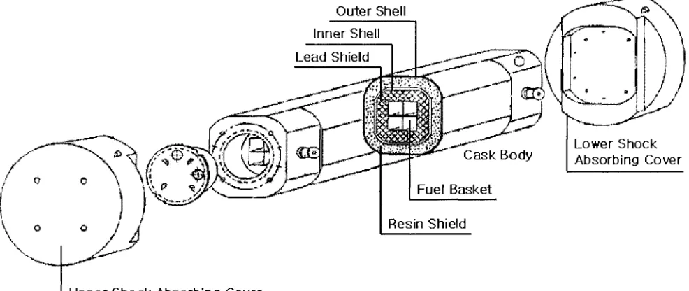
The cask is roughly made of a cask body and two shock absorbing covers to absorb impact energy. Figure 1 is shown the
schematic diagram for the cask, which can be used in transportation of four P W R spent fuel assembly. The body consists of
outer shell, resin shield, inner shell, lead shield and fuel basket and they are joined each other. Total weight of the cask is 37
ton including PWR spent fuel assembly and the height is 4.8m.
The material of the outer shell, the inner shell and the fuel basket is SA 240 type 304 stainless steel and the shock
absorbing cover consists of red and balsa wood. Each material properties are indicated in Table 1 and the wood of which
hardening modulus is zero is assumed by elastic perfect plastic material. The other materials are done elastic plastic material
and the hardening modulus of them is not zero. While stress involved strain is linearly increased with the modulus for elastic
plastic material after the involved stress passes the yielding strength, the stress would not be increased for elastic perfectly
plastic material after the strength.
The shock absorbing cover is made of red and balsa wood. The balsa wood is made disposition on the cask body and red
wood is arranged on the side of the balsa wood such as Figure 2. These covers are joined on bottom and top of the cask using
bolts but we assume in this study that these covers are perfectly bonded on the cask.
Figure 3 shows the half symmetric finite element model. All used elements for the cask are 3 dimension solid element
and flat unyielding horizontal surface is modeled using rigid shell elements. The four P W R spent fuel assemblies of which
weight is about 3 ton, are excepted from FE model because the assemblies' weight is very little comparing with that of
Inner Shell
Lead-Shie~~
i -.-~ .... t i:~
... ~ r ~ ~ ~ ~ ; ; ~ - ~
\
I Upper
S h o c k A b s o r b i n gCover
Outer Shell
/ ~ ~ :
~, ~
...
/__
. ~ , , ~Resin Shield
Table 1 Material properties for the component of the cask[6,7]
Material
304 stainless steel
Resin
Lead
Red wood
Balsa wood
Density (kgf/m 3)
7913
1710
11070
376
160
Young's modulus
(GPa)
186.69
3.86
98.98
1.56
Poisson's ratio
0.32
0.35
0.40
0.49
0.49
Yield strength
(MPa)
258
60
45
0.67 13
Hardening modulus
(MPa)
1894
450
183
I Red wood I
I Balsa wood I
H
m
•
I] ¸ Ill
i[ll
Figure 2 Schematic diagram of the shock absorbing cover
1
the cask body. The 9 meters free drop condition is simulated as the result that the initial velocity, v0=13.3m/s, is applied to the
cask model having small gap between the cask and the surface. The Young's modulus and yield strength of the resin packed
the space between the inner and outer shell is 2% and 23% of it of the steel, respectively. Also the Young's modulus and yield
strength of the lead packed the space between the fuel basket and inner shell is 53% and 2% of steel properties, respectively.
The cask can be assumed the layered shell structure consisted of materials having highly different material property. The
boundary condition between layers has an effect on the analysis results and perfectly bonded boundary condition is employed
in this study.
The model for oblique drop has 68 degree between the vertical center line of the cask and the flat surface to inflict
maximum damage upon the cask. In the puncture condition, the half symmetric model and the full model are used in LS-
I)YNA3I) and ABAQUS/Explicit, respectively. Drop height is 1 meter in the puncture condition so, the initial velocity of the
cask, v0, equals to 4.5m/s. The shock absorbing covers are excepted in the puncture FE model.
LS-DYNA3D
The cask body is modeled using solid element and rigid shell element in LS-DYNA3D. The number of elements is
10976 and the number of nodes is 13694. The FEMB[8] is used as preprocess modeler.
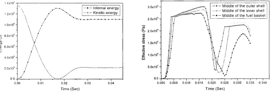
Figure 4 shows the internal & kinetic energy and the effective stress for vertical drop with respect to time on the fuel
basket, the inner and outer shell. The kinetic energy is 1.36MJ initially and approaches the minimum value, 0J, about 7 msec.
O11 the contrary, the internal energy is 0J initially and approaches the maximum value, 1.32MJ, about that time. And then the
kinetic energy is increased from 0J to 0.20MJ and the internal energy is reduced from the maximum to 1.11MJ. After the
effective stress on the outer or inner shell is significantly increased, the stress is sharply dropped. The first time period is said
the time between the increment and drop. The maximum effective stresses on 3 components are found in the first time period.
The values are around 263MPa and held during some miliseconds. After this time period, the effective stresses are increased
to about 220MPa and 100MPa on the outer and inner shell, respectively.
Results for the horizontal drop is denoted in Figure 5. The trend of kinetic and internal energy with time is similar to the
vertical drop but the time approaching to the maximum internal energy is 17 msec and larger than it for the vertical drop. The
maximum effective stress is involved around middle position of the cask body due to bending effect and on the outer shell.
Effective stresses are sharply increased to 260MPa and then are slowly increased again to 300 MPa for the outer shell and
280 MPa for the inner shell. The gentle slope is made by the hardening modulus. After the first time period the effective
stresses on the inner and outer shell have the similar value.
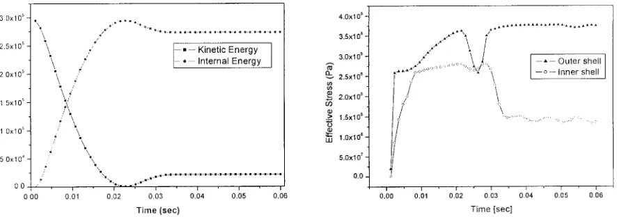
Figure 6 shows the results for the oblique drop. The time approached at the maximum internal energy point is biggest
among the 9 meters free drop condition due to the large deformation of the shock absorbing cover. The condition to inflict the
maximum damage upon the cask says that the initial kinetic energy equals to the maximum internal energy. In other words,
the kinetic energy has to be zero when internal energy arrives to the maximum. But the kinetic energy is not reduced to zero
value at 29 msec, when the internal energy is the maximum. So, the considered oblique drop condition may not be inflicted
the maximum damage on the cask. The maximum effective stress is caused on the outer shell and the value is 260MPa. The
maximum effective stress on the inner shell and the fuel basket is 175MPa and 50MPa, respectively. These values are
equivalent to 67% and 19% of the maximum stress on the outer shell. The effective stress on the outer shell keeps up the
yield strength after the first time period.
Figure 7 shows energy and effective stress on each component for the puncture in half symmetric FE model. The time
approaching the maximum internal energy is 18 msec. The maximum value of the internal energy is larger than the maximum
kinetic energy. This result violates the conservation law of energy and is caused by numerical error. The effective stress on the
outer shell is in fluctuating state from 3 msec to 23 msec while on inner shell increases to 300MPa in the first time period.
The maximum stress on the fuel basket denotes 110MPa. The effective stress on the inner shell is larger than it on the outer
A B A Q U S / E x p l i c i t
Tile FE model in ABAQUS/Explicit uses solid C3D8R element for the cask and rigid R3D4 element for the unyielding
surface. The number of elements used in this model is 13254 and IDEAS is used by preprocess modeler.
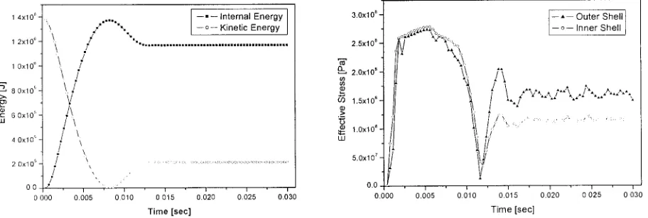
Figure 8-10 show energy and effective stress for vertical, horizontal and oblique drop. These energy plots have a strong
resemblance to them of LS-DYNA3D. For the vertical drop, the maximum effective stress is about 270MPa and is involved
on the inner shell. The hardening behavior is shown in the first time period. After the period, the effective stress is about
160MPa, 60% of the maximuln stress, on the outer shell. And the stress converges into 120MPa, 44% of the maximum, oll
the inner shell. The effective stress is raised into 300MPa for the vertical drop. Also the material hardening behavior is
precisely shown. After the first time period, the effective stress in supported in near the yield stren~h. For the oblique drop,
the effective stress on the outer shell is about 262MPa in the first time period and the value is maintained after the period.
Figure 11 denotes energy and effective stress plots for the puncture. The FE model for the puncture is the full model
without symmetric boundary condition. The maximum kinetic energy is twice of its in LS-DYNA3D as the result that the half
symmetric FE model is used in LS-DYNA3D. While the maximum effective stress on the inner shell keeps 280MPa, it on the
outer shell arrives at 360MPa and the value is maintained after the first time period. The material hardening behavior is
involved on only the outer shell.
DISCUSSION AND C O N C L U S I O N
The energy plots using LS-DYNA3D are good agreement with them by ABAQUS/Explicit. For 9 meters free drop
condition using LS-DYNA3D energy loss is involved by material damping and, for puncture condition energy gain is done.
But for the same condition using ABAQUS/Explicit, this behavior cannot be found.
Table 2 presents the maximum effective stresses under the considered conditions in the first time period. The stress on
the outer shell is larger than it on the inner shell except the vertical drop in ABAQUS/Explicit. The horizontal drop inflicts
the most dangerous on the cask among the 9 meters free drop conditions due to bending effect. Including the weight of P WR
spent fuel assembly, furthermore, the bending effect is increased. And the puncture has more dangerous than the 9 meters fi'ee
drop. While using LS-DYNA3D the maximum stress on the outer shell flutters, using ABAQUS/Explicit it is 362MPa. The
difference between two codes is the largest on the oblique drop. The error is the stress using LS-DYNA3D with respect to it
using ABAQUS/Explicit and is the largest on the oblique drop.
The hardening behavior is well simulated using ABAQUS/Explicit. But using LS-DYNA3D, it can be shown only for
the horizontal drop. Permanent plastic deformation is generated for all the considered conditions and the quantity is large in
the outer shell for the oblique drop and puncture condition.
Table 2 M a x i m u m effective stress on the inner & outer shell using L S - D Y N A 3 D and A B A Q U S / E x p l i c i t
Conditions
Vertical drop
Horizontal drop
Oblique drop
Puncture
LS-DYNA3D (MPa)
Inner shell
260
286
174
302
Outer shell
262
299
262
Flutter
ABAQUS/Explicit (MPa)
Inner shell
278
288
258
Outer shell
273
298
263
362
Error (%)*
Inner shell
-6
280
-33
Outer shell
-4
I
* 100 - Effective stress using LS-DYNA3D x 100
,g
REFERENCES
1. NRC Regulatory Guides, Division 7.
2. Lee, Y.S. and Kim, Y.J., "Dynamic Structural Behaviour of a Shipping Container Under Drop Impact Loading," Trans. on
the 13 th International Conference on the Structural Mechanics in Reactor Technology(SMiRT), Brazil, Vol. 4, 1995, pp.
431-436.
3. Chung, S.H., Ji, P.K., Choi, B.I., Lee, H.Y. and Lee, Y.S., "Conceptual Design of the KN-12 Spent Fuel Shipping Cask,"
Trans. on the 15 a, International Conference on the Structural Mechanics in Reactor Technology(SMiRT), J04/1, Vol. II,
Seoul, 1999, pp. 129-136.
4. Hibbit, Karlsson & Sorensen, ABAQUS/Explicit user's manual, ver. 5.8.
5. Livermore Software Technology Corporation, LS-DYNA3D user's manual, ver. 950.
6. H.J. Rack, G.A. Knorovsky, "An Assessment of Stress Strain Data Suitable for Finite Element Elastic-Plastic Analysis of
Shipping Containers," NUREG/CR-0481,SAND77-1872, Sandia Lab., 1978.
7. Walter A. Von Riesemann, Jommy R. Gues, "The Effects of Temperature on the Energy-Absorbing Characteristics of
Redwood," NUREG/CR-0322, SAND77-1589, Sandia Lab.
8. Livermore Software Technology Corporation, FEMB user's manual.
1 4x10 ~
1 2x10 '3 /
UJ
2 0 x l 0 s •
0 000 0 005 0.010
I
--" -- Internal energy I"X.., [--o-- Kinetic energy I
' i ' i ' i '
0.015 0.020 0.025 0.030 0.000 0.005 0.010 0.015 0.020
Time (Sec) Time (Sec)
3"5x10817 - - " - - Bottom of the outer shell
3.0x10⁸ ~ - - o - - Bottom of the inner shell
/
J --" -- Bottom of the fuel basket
.~x,0.4
T--';;°:°:::"°~:
'
... ~
~ . . . .
t
! t
i \
/L:.,,,,,,..:\/
"
',, !! /
.&
1 5x10 8 ".
0.025 0.030
Figure 4 Energy and effective stresses for the vertical drop using LS-DYNA3D
1 4 x l 0 ~
1 2x10⁶
1 0 x l 06
~ " 8.0x10 s >.,, ~.)
6 . 0 x l 0 s f - LU
4 0 x l 0 s
2 . 0 x l 0 s
0 0 0.00
\
/
\
/
'\./
/
/ •
• [ --..-- Internal energy 1
/ . / - , - . . . \ . - - o - - Kinetic energy
X ,.,io-" ,:, I
\_ j "
¢ ! i
0.01 0.02 0.03 0.04
Time (Sec)
3.0x10 8 ,~,.,,.~ - - A - - Middle of the outer shell
... ~ " - - o - Middle of the inner shell ,,:,~,~t,~'~i~,,.,,. ... ' ::t - - - Middle of the fuel basket
/
",..
"~ 1.5x10 8
"'
~= "°x'°'
tJ
!I"/
i
i'
/
,0x,0. t;
;'\:/
%';'..,
0.0
0.000 0.005 0.010 0.015 0.020 0.025 0.030 0.035 0 040
Time (Sec)
1 4 x 1 0 6
1 2 x i 0 °
1 0 x l 0 8
--) 8 0 x l 0 s
© 6 0 x l 0 s UJ
4 0 x l 0 s
2 0 x l 0 s
O 0 0 O 0
1 8 x 1 0 ~
I
- - - - - Internal e n e r g y I - - o - - Kinetic e n e r g y\ :
\: \:
\ \
\< / /
.}'\
./
\
/
/
./
. / / , / / / \ \ \_ - \3 . 6 x l 0 8
- - ' - - Bottom of the outer shell
3 . 2 x l 0 8
2 . 8 x l 0 8
" ~ ' 2 . 4 x 1 0 8
Q_
o0 oo 2 . 0 x l 0 8
.,..., if)
1 . 6 x l 0 8 >
~ 1 . 2 x 1 0 8
U.I 8 . 0 x 1 0 ~
4 . 0 x l 0 ~ !
0 . 0 . i
0 . 0 0
--~-:,- Bottom of the inner shell . . . Bottom of the fuel basket
,,,:,:~"~'"':"'~;' A
• , , , . •,,
• ,.
.:::; ,,
i: ,~
I ~:'
\
-..: ~: . . . :,_,~_, ,_,:,-o ... :'-o-o-o-~:,_,.~_,:,_ c,_o_,:,_,:,_~ ,-o-
i ' I ' I ' I ' I ' ' i ' i ' i ' i ' i '
0 01 0 . 0 2 0 . 0 3 0 . 0 4 0 . 0 5 0 . 0 6 0.01 0 . 0 2 0 . 0 3 0 . 0 4 0 . 0 5 0 06
Time (Sec) Time (Sec)
Figure 6 Energy and effective stresses for the oblique drop using LS-DYNA3D
. !
0.0 --" ,
0 0 0 1 6 x 1 0 ~
1 4 x 1 0 s
1 2 x 1 0 ~
~ " 1 0 x l 0 ~
> ,
80xlO ~
LU 6 0 x l O ~
4 0 x l 0 ~
2 0 x l O ~
. =, / ~ t t' ,/ , / ',
? ;i.
I - " - Internal e n e r g y t . . , " Kinetic energy
I
0 0 1
1 4 x l 06
* !s ~ C'~ i: ... 3:1:1 iTl:O:l:l't I:11 ... J tl L:t:t 0 121)).lZI ~ I I:1 03 I:l) I I~:O 0:~J33
4 x 1 0 8
3xlO 8 z v (/) (/) I._
.,.., 2x10 8 ._ 13
~ l x 1 0 8
I i i
_ A _ M i d d l e of the o u t e r shell - - o - - M i d d l e of the i n n e r shell • M i d d l e of the fuel b a s k e t
, i )
' , :::
"'~"1 ' I ' i ' i , I ' I ' 1
0 . 0 2 0 . 0 3 0 . 0 4 0 . 0 5 0 . 0 6 0 . 0 0 0.01 0 . 0 2
T i m e (sec)
' I ' i ' i ' I
0 0 3 0 . 0 4 0 0 5 0 0 6
T i m e (Sec)
Figure 7 Energy and effective stresses for the puncture using LS-DYNA3D
1 2 x l 0 °
1 0 x l 0 G
"~" 8 0xl0 5
6 0 x l 0 s LU
4 0 x l 0 s
2 0 x l 0 s
0 0 -"
0 0 0 0
. /
\ / z
\
/.
\ /"
Xvl
./\
I \ / / , !0 . 0 0 5
• " .... - - " - - I n t e r n a l Energy I .., "% - - o - - Kinetic E n e r g y
I
%
" • . . . i . . . . i . . , , l , , l I I l , l,,,I,,ll.,I, III I I I I I n n n II== 1.1,1
3.0x10 8
2.5x10 8
P-- 2.0x10 8
O i._
1 . 5 x l 0 8 13
~ : 1 . 0 x 1 0 8
UJ
5 . 0 x 1 0 7
0.0
" ' " i ' i ' i ' i ' i i ' i i i
0 . 0 1 0 0 0 1 5 0 . 0 2 0 0 . 0 2 5 0 . 0 3 0 0 . 0 0 0 0 . 0 0 5 0 . 0 1 0 0 . 0 1 5 0 . 0 2 0
Time [sec] T i m e [sec]
- - A - - O u t e r Shell 1 oo2~,,,, -- o - - Inner Shell /
\\
-
i~
./\
tj'
. . . . i ' i
0 0 2 5 0 0 3 0
1 4xl 0 ~
1.2x10⁶
1 0 x l 0 ~ ,_.._,
8 0xl 05
©
E 6 0 x l O s LU
4 0 x l 0 ~
2 0xl05
0 0 . " . 0 000 0.005
::',\ ,. ~,:,, ,."
\ ./" .\ ./
.. / \ ,/
<i:, ,"
,/ :tl /
?
1
- - , - - I n t e r n a l E n e r g y I • " " . . . . . . - - o - K i n e t i c E n e r g y
1
I i i i i i i i i i i i i i i i i i i i i i i i i i i i i i i i i i
, ~oOO o°°°':)':'`~°°':)°':":'':''~°°°°':'':'':'':":°~'')c'°':;c'~-
' .- .. . . . -o.-.::o
i , i '''1 i , i , i , i ,
0 010 0.015 0 020 0.025 0.030 0.035 0.040 T i m e [ s e c ]
3.5X10⁸
2.5xl 0 8 '~ .. . . ~ ' ~ ' ~ ... ;-t.t J /i" +\"k / ....
2.0xl 08
1"5x10⁸
~ 1.0x10~
.k ¢ - - • - - O u t e r S h e l l 5.OxlO 7 ~ / j , / - - o - - I n n e r S h e l l
o.o , i , 1 , i , 1 , i , i , i , i 0.000 0.005 0.010 0 015 0.020 0.025 0 030 0 035 0.040
T i m e [ s e c ]
Figure 9 Energy and effective stress for the horizontal drop using ABAQUS/Explicit
1 4X10⁶
1 2X10⁶
1.0xl06
8 0xl05
>, c~ L
d.) 6 0xl05 c- Ill
4 0xl05
2 0xl0 S
0 0 0 00
I • I n t e r n a l E n e r g y I o K i n e t i c E n e r g y \
\
\
\
/"
k\/
/
\
/ \, / \- / i/" 3.0x10 s 2.5x10⁸ 2.0x10⁸ 13. ,..._, 1.5x10⁸ 09 .I.., o 1.0x10⁸ Iii5.0x107 \ , ...,:)_o_o-o -,:,-,~ -o -o-o-c~ --~,-o-,
< ,,.,::,_,:,....,:,~-
I I I ' I ' I ' 0,0 I
0.01 0 02 0 03 0.04 0.05 0.06 0.00 0.01
' ' i , i , i , i ,
0.02 0.03 0 04 0 05 0.06 T i m e [ s e c ] T i m e [ s e c ]
Figure 10 Energy and effective stress for the oblique drop using ABAQUS/Explicit
3 0xl05
2.5x10 s
2 0xl05
>, ~ 1 5 x l O 5
w
1 0 x l 0 5
5 0 x l O 4
.+ 0 o
0 00 " \
\
</
"k j" ,:\
/
/ \\.
,' \...,
i ,
0.01
: K i n e t i c E n e r g y ... I n t e r n a l E n e r g y
J I'l' I 'n-Ill i v j i j i i 0.02 0.03 0.04 0.05 0.06
T i m e ( s e c )
4.0xl 0 a
3.5xl 0 a
3.0xl 0 8
2.5xl 08 i/J I/)
~ 2 . 0 x l 0 a
.~ 1.5xl 0 a o ¢1 It:: 1.0x10⁸ ILl
5.0xl 07
A AA AXa A/" " A ' A A A A A A A A ' A A * ' ' ' ' ' ' ' A A A
• O u t e r s h e l l . . . . . . ,~ '-\ o I n n e r s h e l l
J
/
j
,
':'-o-.:. ,, ".:..).,:....: ... -:. ,.,....: :. ,, .:. :./
i . i , i , i , i , 1 , i
0.00 0.01 0.02 0.03 0.04 0.05 0.06 T i m e [ s e c ]
![Table 1 Material properties for the component of the cask[6,7]](https://thumb-us.123doks.com/thumbv2/123dok_us/1174131.1147598/3.596.194.417.481.652/table-material-properties-component-cask.webp)