18th International Conference on Structural Mechanics in Reactor Technology (SMiRT 18) Beijing, China, August 7-12, 2005 SMiRT18-M02-4
RELIABILITY ANALYSIS TECHNIQUES BASED ON FTA FOR
REACTOR-REGENERATOR SYSTEM
Guangxu Cheng*
Yaoheng Zhang
Department of Chemical Engineering,
Lanzhou Oil Refinery CompanyXi’an Jiaotong University, Lanzhou, Gansu Province,730060
Xi’an, Shanxi Province 710049, P.R. China
Phone: +86+29+82668980, Fax: +86+29+82668322
E-mail: [email protected]
Yajie Liu
Department of Chemical Engineering, Xi’an Jiaotong University
ABSTRACT
Long term running of Fluid Catalytic Cracking Unit (FCCU) is critical important to produce more
gasoline, diesel oil and natural gas for any oil refinery industries. Reactor and regenerator are two key
equipment in FCCU. As a pressure vessels, the safety and reliability of reactor and regenerator is a major
factor which influences on long term running for factories. Therefore, reliability analysis of
reactor-regenerator system is very helpful for prolonging the operating period of the FCCU. Fault tree
analysis(FTA), Fault Modes, Effect and Criticality Analysis (FMECA) are two kinds of effective reliability
analysis methods respectively. Fault-tree modes of reactor-regenerator was established and failure modes
were used to find the weakest components in the reactor-regenerator system. A new approach is proposed in
this study by combining the FTA and FMECA and the reactor system’s reliability was analyzed
quantitatively by the approach. Both an analytical studies and cases verification demonstrated that the
proposed new reliability analysis technique works very well for evaluating reliability of FCCU.
Key Words: Reliability Analysis Fault Tree Analysis FMECA FCCU
1. INTRODUCTION
Reactor-regenerator is an very important equipment in the Fluid Catalytic Cracking Unit (FCCU). In
order to obtain more oil products and save more maintenance cost spent on theequipment, reactor-regenerator
system must be operated in the way of safety running and long inspection intervals. Therefore, reliability of
reactor-regenerator is always paid highly attention by oil refinery industries. The most important
measurement for increasing reliability of reactor-regenerator is to find out all potential risks in the reactor
important components, which play key role on reliability of the system.
Fault tree analysis (FTA) is a reliability assessment technique, which is widely used to hazard
identification that focuses on the causes of an undesired event in the engineering system (Andrew,1993). It
is particularly effective at uncovering hazards due to secondary and tertiary causes. In order to complete the
FTA of a system, it is necessary to identify the function of every component or equipment item in the
system, identify the system boundaries, find out significant failure modes and their consequences, and
display those information by means of tables, figures, or fault trees. Based on analysis of these information,
the reliability of overall system and potential risks could be evaluated.
In reliability assessment of the reactor systems, most studies related to how to construct fault trees
and how to calculate the probability of equipment failure were carried out (Dai,1995 and 1998). However,
the disadvantages of reliability assessment by FTA aims to identify the most significant groups of basic
events rather than to provide exact risk ranking to all the basic events. There is no precise failure mode of
the individual basic event in the different equipment item. FTA is unable to be used to evaluate both the
likelihood and the consequence of the set of events in each scenario as well. An approach was developed in
which the significance of the basic events were established by counting the number of AND gates (Xie,2000),
but in practice, most fault trees consist of a majority of OR gates and maybe a few AND gates. The limitation
of the approach is that it is more qualitative and does not provide an actual value compared with the
importance measures. On the assessment of availability of a FCCU through simulation, Thangamani and
Narendran (1994) studied fault tree by identifying the subsystems and components which are critical to the
availability of a plant. Failure Modes, Effects and Criticality Analysis (FMECA) is another technique of
reliability analysis and is usually performed to provide a better understanding of the risk assessment for
engineering system. The main limitation of the FMECA is that it does not provide quantitative information
or how much more significant one basic event is compared to the rest of the basic events in the system. The
purpose of this paper is to propose a new approach by combining FTA and FMECA, and making use of the
technique for improving the reliability of reactor-regenerator system, ranking outcome of relative
probability of every basic event, finding out the most important basic element of influence system reliability
seriously and using reliability as a basis for prioritizing and managing an inspection program, where
equipment items to be inspected are ranked according to their risk.
2. FAULT TREE AND RELIABILITY ANALYSIS OF REACTION- REGENERATION SYSTEM In order to improve the system reliability and achieve maximum running term of reactor-regenerator, we
should find the most important basic event that affects system reliability greatly. Fault Tree Analysis (FTA) is
conducive to determine the adequacy availability and reliability of a process system. The resulting
arrangement of FTA is a tree-like structure with information flowing from the branch tips, and the single-most
undesired event at the convergence of the branches. FTA can point out the critical aspects of system behavior,
and provide a reference suggestion for the evaluation of modification and a systematic basis for progressing to
a quantitative analysis. In quantitative analysis of reliability, appropriate FTA models should be constructed
by using of OR gates and AND gates. System’s quantitative analysis will facilitate the application of
reliability engineering techniques to the period of design, production and operation stages. Thus the critical
component in the operation should be identified, and relative significance of each component should also be
process and represented pictorially. The Fault Tree of events that are more likely to cause the top event,
which we do not wish them to happen, could be analyzed quantitatively, and therefore the measures should
be taken to avoid the failure occurrence in the system..
The reaction-regeneration system is a key unit which determines highly the income and cost in oil
refinery factories. The reactor and regenerator are the most important pressure vessels in the unit. The
designed parameters of the investigated reactor and regenerator are listed in Table 1 and the procedure of
the system is shown in Figure 1. In order to ensure the reliability of the reaction-regeneration, the study is
confined to evaluate the reliability of the every component in reactor and regenerator and find the potential
factors that may reduce their reliabilities. Several fault tree models are constructed based on the relationship
between the fault tree branches of pressure, temperature and the amount of catalyst loss etc.. The
unstable operating status of reactor and regenerator is assumed as the top event. At the same time, the
intermediate events and the basic events are also determined. They are presented respectively in Table2-5.
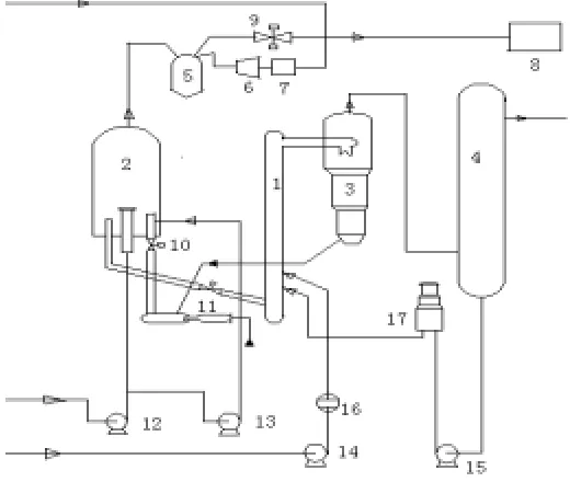
Fig. 1 Schematic of Reaction-Regeneration Process System
1 reactor; 2 regenerator; 3 sedimentator; 4 distillation tower; 5 separator ;6 stack gas turbine; 7 main air
blower; 8 boiler; 9 two direction sliding gate valve ;10 plug valve; 11 sliding gate valve; 12 air
compressor; 13 compressor; 14 raw oil pump; 15 recycle oil pump; 16 heater; 17 heater
Table 1 The designed parameters of reactor and regenerator
Name of items parameters
Temperature at outlet of riser reactor ( C) 510-520
Temperature of raw oil ( C) 170
Temperature of dense phase region in regenerator ( C) 690
Temperature of dilute phase region in regenerator ( C) 720
Pressure of sedimentator (MPa) 0.25
Table 2 Top event
Event label Name of top event
T Unstable operating status of reaction-regeneration process system
Table 3 Intermediate events
Event label Name of events
E1 Output temperature fluctuation of the riser reactor
E2 Pressure fluctuation of the sedimentator
E3 Pressure fluctuation of the regenerator
E4,E7 Fluctuation of recycling amount of catalyst
E5 Fluctuation of the pressure difference
E6 Fluctuation of providing raw feed
E8 Fluctuation of the reaction pressure
E9 Fluctuation of providing raw oil
E10 Fluctuation of providing recycle oil
E11 Regenerator failure
E12 Over liquid level at the bottom of distillation tower E13 Over-high of liquid level in oil-gas separator
E14 Speed over high of air compressor
E15, E17 Fluctuation of air blow in regenerator
E16 Mechanical failure of stack gas turbine
Table 4 Basic events
Event label Name of basic events
x1 Malfunction of flowing meter
x2 Malfunction of raw oil pump
x3 Heat-exchanger accident
x4 Malfunction of flowing meter
x5 Recycle oil pump accident
x6 Heater accident
x7 Malfunction of plug valve in regenerator
x8 Air compressor accident
x9 Main air blower failure
x10 Meter malfunction of raw feed
x11, x12 Indicator malfunction
x13 Gate valve failure of air compressor
x14 Failure of two direction sliding gate valve
x15 Control system malfunction
x17 Boiler failure of carbon monoxide(CO)
x18 Plug valve failure in regenerator
x19 Control valve failure in stream stripping
x20 Control valve failure in loss pressure
x21 Adjusting valve failure between reactor and regenerator
x22 Raw feed with water
x23 Fluctuation of solid material amount in oil slurry
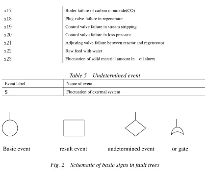
Table 5 Undetermined event
Event label Name of event
S Fluctuation of external system
Basic event result event undetermined event or gate
Fig. 2 Schematic of basic signs in fault trees
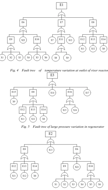
The fault trees are constructed according to the above preparations, they are shown respectively in Figures
3-8. It is noted that all fault trees consist of OR gates.
T
E5 E4
X23 E3
E1 E2
S
E1
Fig. 4 Fault tree of temperature variation at outlet of riser reactor
Fig. 5 Fault tree of large pressure variation in regenerator
E10E9 X22
X3 X2
E6 E7
X4 X5 X6
E14 E13
E12
X11 X12 X8
E11 X12
X7
X8 X9
E15
E3
X9
E14 E13
E12
X11 X12 X8
E16
X15 X16
X14 X17
E8
X8 X12
X11
E12 E13 E14
E2
X13
E8
X6 X5 X4 X1 X2 X3
X22
E9 E10
E6 E8
X1
X8 X9
X20 X7 X19
X18
E4
E17
Fig. 7 Fault tree model of recycling catalyst break
X15 X16 X21
E8
X8 X12 X11
E12 E13 E14
X14
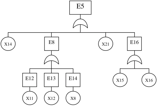
E5
E16
Fig.8 Fault tree of large pressure drop between reactor and regenerator
Usually, a reliability analysis includes two aspects, i.e. qualitative analysis and quantitative analysis.
Qualitative analysis of reliability is used to identify possible ways in which a system failure could occur
and point out proper precautions that will reduce the consequences of such failures. A qualitative analysis
can be performed usefully to identify key parts in the system, to assess the relative importance of all
identified failures. The possible routes that cause the failure occurrences in the reactor and regenerator system
are analyzed by means of the qualitative analysis. The number of minimal cut sets are calculated by following
equations:
T=E1+E2+E3+E4+E5+S+X23 (Eq.1)
Where,
E1=E6+E7+E8 E2=E8+E6+X13 E3=E15+E8+E16+E17+X14 E4=X18+X19+E17+X20+E7 E5=X14+E8+X21+E16 E6=E9+E10+X22
E16=X15*X16 E17=X8+X9 Then,
T=X1+X2+
…
…
+X15+
…
…
+X22+X23 (Eq.2)
Where, Ei is intermediate event; Xj is basic event.
From the analysis result, the number of minimal cut sets is 23, it means that there are 23 routes which
may cause the top event occurrence and contribute to make the system be unstable. In order to carry out the
quantitative analysis and computation, the reliability of the process system was determined and the ranking of
every basic event was performed based on the risk of component, and the component with highest risk in the
system was found out. The probability criticality of basic event may be calculated by,
)
,...,
,
(
)
(
1 2 ni
p
Q
q
q
q
q
i
I
∂
∂
=
i=1,2,3,…,23 (Eq.3)
where qi is the probability of basic event
Q
(
q
1,
q
2,...,
q
n)
is the probability of top event.The relative probability criticality of basic event is,
)
,...
,
(
)
,...
,
(
)
(
1 22 1 n i n i
c
Q
q
q
q
q
q
q
q
Q
q
i
I
∂
∂
×
=
=
)
,...
,
(
)
(
2 1 n iq
q
q
Q
i
Ip
q
(Eq.4)
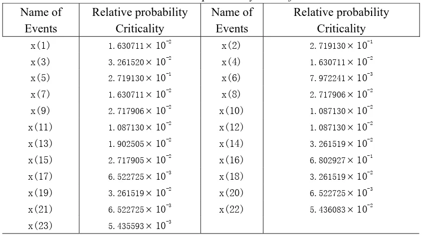
The failure probability values of basic equipment items are extracted from a reference book[6]. Relative
probability level of basic events calculated by Eq.4 are given in the Table 6.
Table 6 Relative probability level of basic events
Name of
Events
Relative probability
Criticality
Name of
Events
Relative probability
Criticality
x(1) 1.630711
×
10-2x(2) 2.719130
×
10-1x(3) 3.261520
×
10-2x(4) 1.630711
×
10-2x(5) 2.719130
×
10-1x(6) 7.972241
×
10-3x(7) 1.630711
×
10-2x(8) 2.717906
×
10-2x(9) 2.717906
×
10-2x(10) 1.087130
×
10-2x(11) 1.087130
×
10-2x(12) 1.087130
×
10-2 x(13) 1.902505×
10-2x(14) 3.261519
×
10-2 x(15) 2.717905×
10-2x(16) 6.802927
×
10-1 x(17) 6.522725×
10-3x(18) 3.261519
×
10-2 x(19) 3.261519×
10-2x(20) 6.522725
×
10-3 x(21) 6.522725×
10-3x(22) 5.436083
×
10-2x(23) 5.435593
×
10-3Reliability analysis begins with a database of generic failure probability for the specific equipment types
(Pg), which is based on a compilation of available equipment failure histories from multiple industries.
Obviously, in practice engineering system, specific conditions can have a major influence on the failure
plant reliability as well. In order to take account these two factors into system reliability evaluation, two kinds
of factors are introduced, the equipment modification factor (Pe) and the management system evaluation
factor (Pm). The generic probabilities (Pg) are then modified by these two terms by multiplying the generic
failure probability by the two modification factors.
Based on the ranking outcome of relative probability criticality of every basic event, a conclusion
could be made that the stack gas turbine, raw oil pump and re-cycled oil pump are more likely to cause the
top event. In other words, those three equipments are the higher risk components in the reaction-regeneration
system. They are the most important components for contributing to system unstable operating than that of
other components, So more attention should be paid on these equipments during reactor running.
Since all the logic gates are OR gates for the studied case, the structure criticality of fault tree for all
basic events are same. The more AND gates the system has, the less important the basic event is. Thus in
order to improve the reliability of the whole system, some measures of adding the AND gates and reducing
the OR gates can be taken by means of standby these important equipments.
3. FMECA OF REACTION AND REGENERATION SYSTEM
Failure Modes, Effects and Criticality Analysis (FMECA) is another important reliability analysis
technique, which includes the identification of critical failure mode or failure criterion. The first step of
FMECA is to list failure modes by potential hazardous and identify the magnitude of their effects on safety,
and to provide a basic theory for quantitative reliability and availability analyses. Thus the maintenance
intervals could be extended if some failure modes are eliminated during the running term. In order to ensure
procedure of FMECA, all conceivable failure modes and their effects on the operational process of the system
must be considered, so historical documents are very useful for FMECA. In this research work, FMECA of
reaction-regeneration system is carried out by proposing and answering a series comprehensive questions of
“what if this happens”, identifying a set of components and then, listing the different ways in which it could
fail for each component. The next step is to consider how the presence of each individual failure affects the
other parts in the system and estimates the implications and severity of each failure mode on the overall
system. By means of FMECA, each failure mode and each dangerous level of the system are defined by
analyzing of fatal degree of each component. In this way, the overall effects of each possible fault and all
failure modes are examined and recorded. The most important parameter for FMECA is Calculate Risk
Priority Number (RPN), it is defined as,
RPN=S
O
D (Eq.5)
Here, S is Risk level, value range: 1—10 O is Failure Probability, value range: 1—10 D is Check-up
difficulty, value range: 1—10.
In order to calculate the RPN, it is necessary to make a preliminary investigation. The investigation
includes examination of the broken parts, looking for clues of causing the failures, getting the documents of
operation conditions accurately and taking photographs from a variety of angles at both the failed zones and
the surrounding areas. To develop a failure definition, flow diagram, failure analysis and preliminary
worksheet should be drawn and interview schedule should be created. The most important step in
calculation of RPN is to get the check-up difficulty (D), we got them by talking to the engineers who involved
in equipment inspection and maintenance, because they knew the failure occurrences at their worksites and
we try to have a correct understanding of exactly what happened and what consequences of events caused.
The data of hazardous level should include the operating conditions, such as time, temperature, pressure,
voltage, load, humidity, lubrication materials, operating procedures, shifts, corrosions, vibration, etc..
Comparing the difference between actual operating conditions and designed conditions, every factor that
may have an effect on stable operation of the system will be found.
Based on the Fault Modes, Effect and Criticality Analysis of reaction-regeneration system, Risk Priority
Number is presented in Table 7.
Table 7 FMECA Form of Reaction-Regeneration System
Equipment item Failure mode Hazardous level ( S )
Probability ( O )
Check-up difficulty ( D )
RPN
Nozzle coking 3.5 10 2 70
Reactor
Crack of expansion joint
9 3.5 2.5 79
Ex-valve Rupture 8.5 2.5 3 64
Valve Jam 8.5 4.5 3 115
Meter Well out of control 5 5 2.5 63
Air compressor Over large vibration 8.5 4 2.5 85 Separation or bulge
of hex steel grating
2.5 10 1.5 37.5
Jam of sealing leg 9.5 1.5 1.5 21.4
Jam of wing valve 9.5 1.5 1.5 21.4
Chemical corrosion 7.5 1.5 8 90
Regenerator
H2S corrosion 8 1.5 8 96
Sedimentator Coke 3.5 9 2 63
Separator Dew point
corrosion
4.5 5.5 7.5 186
Sulfur corrosion 3.5 8.5 2.5 74.4
Heater
Wear 3.5 6.5 2.5 56.9
Booster blower Wear of thrust block
8.5 3.5 2.5 74.4
Vibration 9.5 9 2.5 214
Stack gas turbine
Wear 4.5 8.5 4.5 172
Pumps Vibration 8.5 6.5 3 166
From the Table 7, it could be pointed out that the RPN of stack gas turbine, pump and separator are
larger than those of other equipments. It means that the risks of these three devices are higher and they are the
weaker components in the reaction-regeneration system. Thus it is necessary to take measures on them for
reducing their failure probability. In the regenerator, chemical corrosion and H2S corrosion are ranked on
reduced. Meanwhile, the coking problem of reaction-regeneration system is also an important factor of
influence on normal stable running, coking happened in many devices, such as reactor, sedimentator etc..
The coking will influence the normal operating of the whole system and product quality.
The above analysis based on FTA and FMECA illustrates that the reliability analysis could be easily
expanded to a process of distillation system and absorbing stabilizing system in FCCU, even more to a whole
oil refinery plant. However, the reliability analysis becomes increasingly complicated for a process plant. A
thorough FTA and FMECA of a process plant can easily take several days or months. When we consider the
number of components to be evaluated, and the number of appropriate ways of inspecting them, the task of
setting weakest component can appear very significant (the weakest component means the highest risk
equipment). A new approach of combining the FTA and FMECA is proposed in the research, based on the
new approach, the weakest component is found out firstly by means of FTA, and then the analysis will be
focused on this weakest component. Its failure modes, hazardous level and check-up difficulty are
investigated and risk levels will be ranked by RPN. Therefore, the reliability analysis could be completed in a
shorter period. It is shown that the new approach is a useful reliability analysis methods for a complex
engineering system.
4. CONCLUSIONS
FTA is an effective method, which can evaluate system reliability and safety from top event to basic
event, and FMECA is a quantitative reliability analysis from basic event to top event. But both of them have
limitations using in practice engineering. Based on the advantages of FTA and FMECA, respectively, a new
approach of reliability assessment was proposed by combing the FTA and FMECA. The connection
between FTA and FMECA are established as well. The new approach not only aims to identify the most
significant groups of basic events, but also points out quantitatively the potential risk and failure modes. The
approach is used to identify the component that most probably caused the reaction-regeneration system to
fail.
Several fault trees are constructed, and the possible critical routes of causing equipment failure are
given out. The reliability assessment of the critical components are described based on FEMCA. The
weakest components of the system are pointed out by means of combining FTA and FMECA.
The failure models in the system are determined by defining a unstable operating as the top event,
and finding all the equipment items as the basic events. Three major potential risks which can cause the
unstable operating for the reaction and regeneration system are fund out by ranking Risk Priority Number,
they are vibration of stack gas turbine, wear of pumps and dew point corrosion of separator. The verification
of engineering cases demonstrates that the approach is suitable for estimating reliability of a complex
process plant.
REFERENCES
1. J.D.Andrew, T.R.Moss, (1993), Reliability and Risk Assessment, Longman Scientific, London.
2. Dai Shuho,(1998), Methodology for predicting the occurrence of failure events for pressure vessels used in
the process industry, International Journal of Pressure Vessels and Piping, Vol.75, pp.221-228.
3. Dai Shah,(1995), A study on the residual life prediction for pressurized tubes of an industrial furnace
Pressure Vessels and Piping, Vol.63, pp.111-117.
4. M.Xie, K.C.Tan, K.H. Goh,(2000), Optimum prioritization and resource allocation based on fault tree
analysis, International Journal of Quality & Reliability Management, Vol.17,No.2, pp.189-199.
5. G.Thangamani, T.T. Narendran, (1994), Assessment of availability of a fluid catalytic cracking unit through
simulation, Reliability Engineering and System Safety, Vol.47, pp.207-220.