SEISMIC CAPABILITY OF CANDU
®6 ECC SYSTEM
Richard Z. Chen, Tarek S. Aziz, and Sudip Adhikari
Atomic Energy of Canada Limited, Mississauga, Ontario, Canada
ABSTRACT
The nuclear industry is frequently faced with decisions related to the seismic design of the existing operating nuclear power plants. Earthquakes beyond the design basis are of interest as new information, mainly seismological, becomes available. Current design practice for nuclear power plants ensures an adequate design from a deterministic perspective. The current design practice, however, does not provide a picture of the actual margin to failure, nor does it provide enough information to make realistic estimates of seismic risk. Seismic assessments using acceptable probabilistic methodology are beneficial in improving the knowledge of the plant seismic capability and in identifying plant specific vulnerabilities to severe seismic events, so that various options to enhance the plant seismic capability can be made available.
The seismic capability of the Emergency Core Cooling (ECC) system of a CANDU® 6 nuclear power plant was recently assessed with the objective to demonstrate the robustness in plant safety. In this paper, due to space limitation, only the seismic capability analysis of the steel dousing platform, which is a part of the overall seismic capability assessment of the ECC system, is presented. The seismic design philosophy and seismic design approach for the platform are reviewed. The critical failure modes for various components of the platform are investigated and the capability evaluations are performed. In addition, options have been identified to enhance the seismic capability of the dousing system.
INTRODUCTION
Various options are available to improve containment performance of a CANDU® nuclear power plant under severe accident conditions caused by external events such as an earthquake. One of these options is to improve the performance of the Emergency Core Cooling (ECC) System. The function of the ECC system of a CANDU® 6 nuclear power plant is to provide cool light water to the Primary Heat Transport (PHT) System, for fuel cooling and inventory makeup, if the PHT System is breached creating a Loss of Coolant Accident (LOCA). The ECC system can also provide heat sink coverage on a manual initiation basis.
The ECC System is composed of three stages: High Pressure (HPECC), Medium Pressure (MPECC), and Low Pressure (LPECC) or Recovery Stage. The HPECC Stage uses gas pressure from gas tank to inject water automatically into the reactor core from water tanks located outside the reactor building. The MPECC Stage automatically supplies water from the dousing tank, part of which is reserved for ECC, to the reactor core using the recovery pumps. When this water supply is depleted the LPECC or Recovery Stage is automatically initiated to recover water that has collected in the reactor building basement, and pump it back into the reactor core via the ECC heat exchanger.
The seismic capability of the ECC system of a CANDU® 6 nuclear power plant was recently assessed with the objective to improve the plant safety. As a part of the assessment, a seismic walkdown was performed to screen out the equipment and structures that are considered seismically rugged based on earthquake experience. For the remaining items after the screening analysis, a seismic capability analysis is required. These items include the dousing system, which is located at a very high elevation inside the reactor building and has high seismic response.
In this paper, the seismic capability of the steel dousing platform, which supports the dousing system, is discussed. The seismic capability analysis calculates the median seismic capacity of individual component or structure and the associated randomness and uncertainty. The results of the analysis are presented as High Confidence of Low Probability of Failure (HCLPF) seismic capacity in terms of peak ground acceleration.
DESCRIPTION OF THE DOUSING SYSTEM
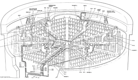
The main function of the dousing system is to suppress the pressure peak generated inside the containment as the results of a break in any of the high energy pipes in a severe accident. As shown in Figure 1, the key components of the dousing system are dousing tank, spray headers, and piping andisolation valves. If a high energy pipe within containment fails, then
®
CANDU (CANada Deuterium Uranium) is a registered trademark of Atomic Energy of Canada Limited (AECL).
the pressure inside containment will rise due to the flashing of water to steam that occurs at the break. At the dousing "on" setpoint the isolation valves open and a flow of water, from the dousing tank to the spray nozzles, will be established by gravity. The spray nozzles break up the water flow into a fine spray and this spray assists in condensing the steam, which helps to reduce the steam pressure. When the pressure drops below the dousing "off" setpoint the isolation valves close and the dousing flow is stopped. Depending on the conditions of the break, the system may cycle on and off until the dousing water is exhausted, or it may only cycle once.
The dousing tank is located in the dome of the reactor building and holds water during operation of the reactor, for emergency use as dousing water and as ECC water. The dousing tank was designed for both the conventional applicable loads and additional hypothetical overpressure to ensure the tank and its support will not fail.
The dousing platform, which supports the dousing headers and the spray piping system, is supported on the containment wall at its perimeter and on the hangers attached to the dousing tank.
Figure 1 Dousing System
FRAGILITY METHODOLOGY AND APPLICATIONS
The seismic capability analysis for the dousing platform is performed following the methodology described in EPRI TR-103959 (Reference [1]). Results of the fragility analysis are median seismic capacity (Am) and its associated randomness and
uncertainty parameters (βR and βU). Family of seismic fragility curves may be described by these three parameters, i.e., Am, βR and βU, where,
Am = Median seismic input parameter capacity (e.g., median ground acceleration capacity), βR = logarithmic standard deviation due to randomness in the capacity,
βU = logarithmic standard deviation due to uncertainty in the median capacity.
The random variability βR represents dispersion in the results, which cannot be reduced by gathering more data or more
detailed analysis. It is due to the randomness in the earthquake time-history and in the response of the structure when the earthquake is represented by one input parameter like peak ground acceleration (PGA). On the other hand, the uncertainty
βU, represents dispersion in the results due to inadequate knowledge, lack of data or insufficient analyses and test results. A commonly used value, which describes the seismic capacity of a component or structure, is the High Confidence of Low Probability of Failure (HCLPF) value, which represents, with a 95% confidence, that the probability of failure of a component or structure will not exceed 5%. It is calculated by:
HCLPF capacity = Am exp [-1.65(βR + βU)] (1)
The intent of the seismic PSA fragility analysis is to calculate median-centered (or best estimate) response and capacity as opposed to a seismic design response of a structure or component. For the seismic fragility evaluation, the so-called “Separation of Variables” approach is commonly used. The median seismic capacity is determined based on a series of median-centred capacity factors and response factors used in computing the seismic response of structures. An intermediate variable, called “factor of safety”, can be defined.
The factor of safety, Fm,is defined as the ratio of the median ground acceleration capacity to the Design Basis
Earthquake (DBE) acceleration used in the design. Thus:
Am = Fm * ADBE (2)
For building and structure, the median factor of safety is calculated by
Fm = FC. FSR
= (FS * Fμ) * (FSS * FD * FM* FMC * FEC * FED * FSSI) (3)
where,
Fm = the overall factor of safety,
ADBE = Design Basis Earthquake (DBE) acceleration,
FC = seismic capacity factor,
FSR = building response factor,
FS = strength factor, defined as the ratio of median-centered member strength to the design forces with alogarithmic
standard deviation βS associated with it,
Fμ = inelastic energy absorption factor, related to the ductility of the structure with a logarithmic standard deviation βμ associated with it,
FSS = spectral shape factor, to account for the difference between the response spectra used for design and the median
ground response spectrum for the site,
FD = damping factor, to account for conservatism in the damping value used for design,
FM = modelling factor, to account for either conservatism or unconservatism in the structural modelling for the design
seismic analysis,
FMC = modal combination factor, to account for either conservatism or unconservatism in the modal combination method
used in the design analysis,
FEC = combination of earthquake components factor, to account for either conservatism or unconservatism in the
earthquake components combination method used in the design analysis,
FED = horizontal earthquake direction factor, to account for conservatism or unconservatism in defining the DBE peak
ground acceleration,
FSSI = soil-structure interaction effect factor.
For structures analysed for DBE or the corresponding FRS, the median factor of safety and variability parameters based on the design DBE structural analysis can be computed. The overall variability parameters can be calculated as the square root of the sum of squares (SRSS) of the randomness or uncertainty associated with each of the factors in equation (3), as following:
βR = (βR,C2+βR,SR2)1/2 (4)
βU = (βU,C2+βU,SR2)1/2 (5)
where,
βR,C = logarithmic standard deviation due to randomness associated with seismic capacity factor
βR,SR = logarithmic standard deviation due to randomness associated with building response factor
βU,C = logarithmic standard deviation due to uncertainty associated with seismic capacity factor βU,SR = logarithmic standard deviation due to uncertainty associated with building response factor
Using equations (1) to (5), the HCLPF values can be obtained.
Median Structure Capacity Factors
Capacity analysis uses the original design forces as seismic demands and realistic capacity (not limited by code design capacity) and ductility calculations as the median capacity. The primary load carrying system of the structure has to be identified. Then the critical structural components of the system have to be examined (walls, slabs, columns, masonry block walls, foundations, etc.). Finally, the expected median capacities and associated variability of the various types of the load-carrying elements are calculated.
Plastic hinges may form on some sections of the steel frame prior to failure in steel structure. In defining failure of the structure, one must estimate the limit of inelastic deformation that is tolerable before affecting safety related items. This is accounted for in the fragility evaluation by the so-called inelastic energy absorption factor.
a) Strength Factor FS
Strength factor Fs, can be evaluated as follows:
FS = (Median Capacity - NOL)/ Design Seismic Demand,
where, NOL is demand due to normal operating conditions or loads. Conservatism in the design seismic demand is normally accounted for in the structure response factors. In order to calculate the median capacity, median material strengths should first be determined. The median material strengths used in this fragility analysis are discussed below. 1) Concrete Compressive Strength
The evaluation of the strength of most concrete structures, whether loaded in compression or shear, is based on the concrete compressive strength, f 'C. Concrete compressive strength used for design is normally
specified as some value at a specific time from mixing (for example, 28 or 90 days). This value is verified by laboratory testing of mix samples.
The concrete utilized in the construction of most of safety related structures was specified to have a minimum compressive strength of 3,500 psi at 28 days. The concrete used in the containment shell wall was specified to have 5,000 psi strength at 28 days. Site specific concrete test data for the concrete structures were not readily available. Thus generic concrete compressive strength based on experience database was used to develop the median compressive strength for this study. For this analysis, a median factor of 1.2 for 28-day strength is used. As concrete ages, its strength increases. This must also be accounted for in determining the median strength compared to the design strength. Reference [2] suggests a median factor of 1.2 for relating the strength of aged concrete to the 28-day strength. A logarithmic standard deviation associated with the 28-day aging factors was estimated to be 0.10. Thus, the factor relating median compressive strength including aging effects to design compressive strength is about 1.44.
2) Reinforcing Steel Yield Strength
Grades 60 reinforcing steel with yield strength of 60 ksi was used in the construction of the reactor building and other structures. Based on Reference [1], the median yield strength and logarithmic standard deviation, for the reinforcing steel are estimated to be 66 ksi and 0.09. These values were used in the evaluation of the concrete structures.
3) Structural Steel Strength
The structural steel has yield strength of 44 ksi (G40.21, 44W). As per Reference [2], the median yield strength of structural steel was taken to be 1.2 times code specified minimum yield strength with a logarithmic standard deviation of 0.12.
4) Bolts Strength
ASTM-A325 bolts were used in the bolted connections. Either the ultimate median strength of 142 ksi (Reference [2]) or the allowable design stress in the design calculation could be used. For expansion anchor bolts, the allowable forces with a safety factor of 4 should be used median capacity of the anchor bolts.
b) Structure Inelastic Energy Absorption Fμ
The seismic capacity of a structure can be evaluated more accurately if in addition to its strength capacity the inelastic energy absorption of the structure is accounted for.
Median Structure Response Factors
These factors are used to account for various sources of conservatism encountered in the nuclear building design process.
a) Spectral Shape Factor FSS
Median spectral shape factor, FSS, accounts for difference between design and median site-specific ground response
spectra. The comparison is carried out at dominant structure frequencies. The difference between design and median structure damping is normally included in FSS. Therefore,
FSS = SAd/SAm,
where,
SAd = Spectral acceleration for design ground response spectrum and design damping,
SAm = Spectral acceleration for median ground response spectrum and median damping.
Spectral shape factors were determined from the ratio of spectral acceleration at design damping to the 5% damped median spectral acceleration with both spectra normalized to 0.20g PGA in this case. The spectral shape factor was determined from the ratio of the design ground spectral acceleration to the median ground spectral acceleration at the fundamental frequency of the structure.
b) Damping Factor FD
In computing the spectral shape factor of safety, it is convenient to combine the damping and ground response spectrum effects. This implies a factor of safety of unity on damping alone since it has already been included in the factor of safety on spectral shape. In this fragility analysis, the 10% median damping is used for the prestressed concrete structures, concrete structures, and bolted steel structures.
c) Modelling Factor FM
Median modelling factor, FM, accounts for accuracy of design analysis model. It can account for minor frequency
shifts as follows:
FM = SAm (f=fm)/SAm (f=fd),
where,
SAm = Spectral acceleration for median ground spectrum,
fm, fd = median and design frequencies.
Design analysis models including mass lumped stick models are generally considered to be median-centred. Therefore, FM is typically equal to 1.0.
d) Modal Combination Factor FMC
Median modal combination factor, FMC, accounts for difference in modal combination between design method and
median method.
FMC = Vd/Vm,
in which,Vd, Vm are seismic loads with modal responses combined according to design method and median method
respectively.
In the seismic design analysis of the existing structures, the individual modal responses were combined by the SRSS method. The SRSS combination of modal responses tends to be median-centered. The median modal combination factor of safety was therefore taken to be 1.0 for the structure evaluation conducted here. On the other hand, absolute sum is an upper bound.
e) Combination of Earthquake Components FEC
Median earthquake component combination factor, FEC, accounts for the difference between the design method and
the median method for the combination of different earthquake components.
FEC = Vd/Vm,
where, Vd, Vm are seismic loads with directional responses combined according to design, median methods respectively.
Current practice is to combine the co-linear responses for the three principal earthquake directions by the SRSS method. Combination by SRSS or 100-40-40 methods is both considered median-centred and thus FEC is equal to 1.0.
f) Soil-Structure Interaction Effects FSSI
For structures founded on stiff rock, fixed base analysis is considered median-centred. The reason is that there is small difference between actual parameters representing stiff rock when compared to fixed base models. Therefore, a factor of safety of unity is assigned to this parameter with almost no variability.
SEISMIC CAPABILITY ASSESSMENT
The six dousing headers and dousing spray piping shown in Figure 1 are supported by a dousing steel platform that comprises 6 massive “A” sections in plan view. The dousing platform and its hangers are partially shown in Figure 2. The steel platform is supported by 12 structural steel hangers from the central wall of the inner dome (dousing tank) and by 18 brackets bolted to embedded parts in the concrete containment wall. These 18 brackets support one end of each of the main beams of the dousing platform. The beams are not bolted to the brackets but rest on Lubrite pads to allow for radial horizontal movement. Movement in rotational plan view direction is prevented by steel bumpers with hard rubber cushion glued to the bumper. Movement in the radial horizontal plan direction would be limited by the other end of the beam coming up against the containment wall.
Figure 2 Dousing Platform and Hangers
As part of the seismic capability assessment, a seismic walkdown was performed. The main purposes of the seismic walkdown are to:
1. Based on seismic capability engineer’s experience and judgment and use of earthquake experience data as appropriate, screen out from the seismic capacity analysis all elements, for which the experts are prepared to state the HCLPFs at or above the specified screening level;
2. Define potential failure modes for the remaining items that are not screened out;
3. Add to the seismic capacity analysis any items of seismic interaction that the walkdown team judges to create potential issues.
The seismic walkdown team consists of seismic capability engineers, seismic system engineers and PSA engineers. The seismic walkdown is primarily the responsibility of the seismic capability engineers.
Various failure modes are considered in the seismic capacity analysis for the dousing platform. These failure modes include:
a) the failure of the platform structural steel,
b) the failure of the platform supports on the containment wall, c) the failure of the platform hangers.
According to the seismic walkdown, the dousing headers and spray headers are considered well supported to the steel structures. It was concluded that the dousing platform steel appears to be generally in good condition. A review of the structural drawings and analysis reports also confirms that the platform structural steel has adequate seismic capability. Therefore, the failure of the platform structural steel is not considered as the dominant failure mode.
The structural drawings and analysis reports for the platform supports on the containment wall, including the 18 brackets and the embedded parts in the containment wall, are reviewed. It is found that the platform supports have adequate design margin. Also the seismic capability of the containment wall is assessed and it is concluded that the containment wall has large seismic capability. Therefore, the failure of the platform supports on the containment wall is not considered as the dominant failure mode.
The technical documents for the dousing platform hanger seismic design and the structural drawings of the hangers have been reviewed. Each hanger consists of two structural steel channels with a length of approximate 29 feet pinned at both ends. The two steel channels are joined together at every six feet interval by a plate spacer. Each spacer is welded to each channel with two 6” long 3/8” fillet welds. The top end of each of the 12 vertical structural steel hangers is attached to the embedded part in the inner dome. The bottom end of each hanger is connected to the horizontal structural steel of the dousing platform by a large horizontal pin secured by a cotter pin, to provide a flexible connection. The hanger was mainly designed for tension. A structural assessment for the hanger reveals that the hanger has large seismic capability to resist tension load. However, it is found that as the seismic demand increases, the hanger could be subjected to compression. The hanger is long and is unbraced. Therefore, the seismic capability of the hanger is governed by the buckling of the structural steel channels due to a combination of compression and bending moment under seismic loads. The bending moment in the hanger is mainly due to the horizontal components of an earthquake. As the hanger is located at a very high elevation of the reactor building, the horizontal earthquake forces are also very high. Based on this finding, the seismic fragility of the dousing platform hanger is calculated. In this analysis, the following stability criteria is used:
Fs⋅Pseismic−Pdead
A
Fa_m
fb_m⋅Fs
Fb_m
+ ≤1
in which, Fs is the strength factor that accounts for inelastic energy absorption, spectral shape, median damping etc., Pseismic
is the compression in the hanger due to seismic load, Pdead is the axial load due to the dead loads, A is the section area of the
hanger, Fa-m is the median allowable compressive stress, fb-m is the median computed stress in the hanger due to bending, Fb-m
is the median yield stress of the steel.
It is found that, for the buckling failure mode of the dousing platform hanger, the corresponding HCLPF value in terms of peak ground acceleration is larger than the design basis earthquake. The HCLPF value is, however, below the target set for the structures inside the reactor building, which is beyond the design basis earthquake. It is noteworthy that the buckling failure of the dousing platform hanger makes the hanger behave like a steel cable with no compression resistance. This does not mean that the dousing platform will collapse since the tension capability of the hanger remains adequate for this scenario. Nevertheless, recommendations are made to reinforce the hangers by adding braces and/or stiffened plates to enhance the seismic capability of the dousing system.
CONCLUSIONS
In this paper, the seismic capability assessment of the dousing platform, which is part of the ECC system of a CANDU® 6 nuclear power plant, is discussed. The seismic fragility methodology is reviewed and its applications to this study are presented. The seismic fragility analysis calculates the median seismic capacity of individual component of the dousing platform and the associated randomness and uncertainty. It is found that the dominant failure mode is the buckling of the platform hanger due to combined compression and bending under severe seismic loads. The seismic capability of the dousing system can be greatly enhanced by reinforcing the hangers with relatively simple modifications such as additional braces and stiffened plates.
REFERENCES
[1] EPRI report, "Methodology for Developing Seismic Fragilities", EPRI TR-103959, Final Report, June 1994.
[2] EPRI report, "A Methodology for Assessment of Nuclear Power Plant Seismic Margin", EPRI NP-6041-SLR1, August 1991.